R E S E A R C H
Open Access
Preliminary Monte Carlo simulations of linear
accelerators in Time-of-Flight Compton Scatter
imaging for cargo security
Nick Calvert
1*, Edward J Morton
2and Robert D Speller
3Abstract
The economic impact of illicit trade is in the trillions of dollars per year, with a proportion of this trade concealed within cargo containers. The interdiction of this trade relies upon efficient and effective external screening of cargo containers, typically using x rays. The present work introduces a technique of x-ray screening that aims to increase the efficiency and effectiveness of x-ray screening. Traditional X-ray screening of cargo containers is performed using high-energy (MV) transmission imaging or low-energy (kV) Compton scatter imaging to provide two-dimensional images. Two-dimensional images can contain complex, overlapping objects and require significant experience and time to interpret. Time-of-Flight information can be used in conjunction with Compton scatter imaging to provide information about the depth of each Compton scatter interaction, leading to three-dimensional images, reducing false positives and image analysis time. The expected Time-of-Flight from photons scattered back from a set of objects is well defined when the photons are produced with a delta-type (infinitely narrow) pulse duration, however, commercially available linear accelerators used for cargo screening typically have pulse widths of the order of 1μs. In the present work, the possible use of linear accelerators for Time-of-Flight Compton scatter imaging is investigated using a mixture of analytic and Monte Carlo methods. Ideal data are obtained by
convolving a number of wide x-ray pulses (up to 5μs) with the expected Time-of-Flight from a set of objects using a delta-type pulse. Monte Carlo simulations, using Geant4, have been performed to generate x-ray spectra produced by a linear accelerator. The spectra are then used as the input for detailed Monte Carlo simulations of the Time-of-Flight of photons produced by a single linear accelerator pulse scattering back from a set of objects. Both ideal and Monte Carlo data suggest that Time-of-Flight information can be recovered from a wide linear accelerator pulse, provided that the leading and falling edge of the pulse are sharp. In addition, it has been found that using a linear accelerator leads to double the amount of Time-of-Flight information as both the leading and falling edge are utilised (unlike for a delta-type pulse).
Keywords:Compton scatter, Cargo security, Time-of-flight imaging
Background
Current cargo screening techniques
Transporting goods by sea in containers is the most effi-cient mode of the transportation of goods (World Ship-ping Council, 2012). Moreover, 90% of the world’s trade is transported by sea (Kaluza, et al., 2010). Securing cargo containers is, therefore, of high economic import-ance as disruption to sea trade could have a significant
economic impact globally. The security threats potentially smuggled in cargo containers are wide ranging from radiological and nuclear material (McLay & Dreiding, 2012) to drugs (McNicholas, 2008) and humans (Kyle & Liang, 2001). Due to its nature, estimating the scale and distribution of goods smuggled by container is difficult. One method of estimating the distribution is to look at the global illicit trade market. Of items that could be concealed within containers, Havocscope estimates that counterfeit drugs have the largest black market value, followed by counterfeit electronics (Havocsope 2013). Al-though this list does not specify how much of these items * Correspondence:[email protected]
1
Department of Security and Crime Science, University College London, 35 Tavistock Square, London WC1H 9EZ, UK
Full list of author information is available at the end of the article
are transported by container, it can be used as a guide-line. There are some more accurate estimates, for ex-ample the United Nations Office on Drugs and Crime (UNODC) estimates that approximately 66 metric tons of cocaine was shipped to Europe in 2008 (UNODC, 2010). In an effort to counter these threats, radiation-based screening methods have been incorporated into cargo security via the introduction of passive detection ofγrays and neutrons, and active radiography (imaging) (Wein, et al., 2006). In order to maintain the efficiency of the trade system, these screening methods must be as fast as possible and the results produced must be easily analysable and accurate, since false positives can result in a container requiring manual inspection, which is an expensive and time consuming procedure (McLay & Dreiding, 2012). False negatives are also a problem as they result in illicit materials penetrating the borders of a country and result in further crime occurring. Technological advances in cargo screening should therefore be aimed at increasing the effectiveness by im-proving image quality, simplifying the resultant images (e.g. three dimensional images) and thereby reducing the false positives and negatives at the same or lower ra-diation dose to current systems, without compromising the efficiency of the trade system or having too high a cost. The present work introduces a possible new tech-nique that aims to produce images that are easier to in-terpret and analyse than current methods, increasing efficiency and decreasing the number of false positives, whilst using currently available x-ray sources, thereby keeping costs to current levels.
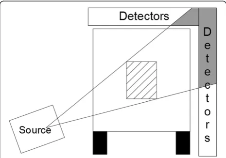
There are two types of x-ray imaging used for cargo screening, transmission imaging and Compton scatter imaging (CSI), which have different advantages. Trans-mission imaging was invented by William Röntgen in 1895, and is still commonly used in hospitals as well as security screening. X rays are created using an elec-tronic source, and fired at a cargo container. The x rays that pass straight through are detected on the opposite side of the container by a set of detectors, creating a one dimensional image. The source and detectors are moved along the length of the container, or vice-versa, and the data from the detectors is combined to form a two dimensional image of the container (Chen, 2005). An illustration of the components required for this technique is shown in Figure 1.
Transmission images show materials of high atomic number with higher contrast to air than materials of the same thickness but lower atomic number. Hence, thin pieces of metal, for example a knife blade or gun, are clearer in the image than thin pieces of explosives or drugs.
In order to penetrate through a densely packed con-tainer, high-energy x rays are required. These are
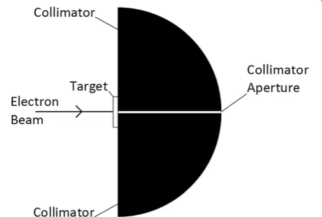
produced using a linear accelerator, which fires electrons at a metal target, typically tungsten. The electrons interact with the electrostatic field of the tungsten atoms becom-ing deflected and losbecom-ing energy in the form of an x ray. Linear accelerators produce pulses of electrons and, there-fore, pulses of x rays, with each pulse duration of the order of 1μs (see (Langeveld, et al., 2011) for an example of a linear accelerator with a 0.1 to 4.7μs variable pulse width). The electrons are accelerated inside the accelerator using a potential difference typically set to 4, 6, or 9 MV for cargo imaging. The resultant x rays from a 4 MV acceler-ator can have a maximum energy of 4 MeV, 6 MeV from a 6 MV accelerator, and so on. However, the x rays are pro-duced with a spectrum of energies ranging from 0 eV to the maximum.
CSI, or backscatter imaging, is also widely used for se-curity purposes. This technique no longer detects the x rays that penetrate through a container, but rather the x rays that scatter back from the container to the detector. As with transmission imaging, x rays are electronically produced and fired at the cargo container, however, the detectors are now placed on the same side as the source. Typically, the x-ray source is collimated into a fine beam, called a pencil beam. This beam is swept over the object repeatedly, whilst the source and detectors are moved along the length of the object to create an image (Dinca, et al., 2008). When an x-ray photon undergoes a Compton scatter, it changes direction and also loses en-ergy. The loss of energy creates a problem for CSI. As energy decreases, the probability of the x ray being absorbed increases. The result is that a significant num-ber of x-ray photons that scatter within an object, are then absorbed in that object. This leads to a reduction in the number of scattered x-ray photons detected, which reduces the image quality. The features of an image taken using CSI can be seen to be complementary to transmission images. Materials with high atomic number
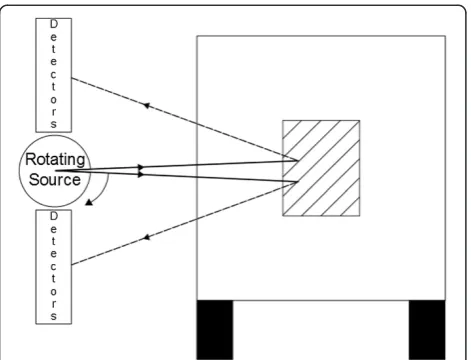
have higher scattering probabilities than those with lower atomic numbers, however the probability of ab-sorption is also higher in these materials, resulting in more photons scattering and then absorbing. Hence, plastic explosives and drugs have a higher contrast to air, than guns or lead shielding. An illustration of a CSI system is presented in Figure 2.
Low-energy x rays are typically used for CSI, up to 225 keV (Chalmers, 2004), and produced using x-ray tubes. The disadvantage of using low-energy photons is the reduced penetration of the x rays. That is to say, as the probability of x rays fully penetrating densely packed cargo is so low, the far side of the container will not be imaged. The Compton scatter interaction also has an upper energy limit to photons that are scattered back. Regardless of the energy of the incident radiation, a 180o scattered photon will never have energy of greater than 255.5 keV (Knoll, 2010: 324). The energy of photons scattered through varying angles has been plotted and shown in Figure 3, for different incident photon ener-gies. This again limits the penetration of a CSI system.
Problems with current screening methods
Both transmission and CSI systems have advantages and disadvantages. Using a CSI system results in higher con-trast for plastic explosives and drugs, requires access to only one side of the container, and produces more photographic style images, which are easier to interpret and analyse. On the downside, they have limited pene-tration and metallic objects may be invisible. Transmis-sion images have very high penetration and show up metallic objects well, however they require access to both sides of the container, and the resultant images can be large and complex with many overlapping objects.
The common disadvantage of both imaging techniques is the production of two-dimensional images only. Two-dimensional images of cargo can lead to many objects overlapping and creating complex features within the image, leading to an increased analysis time required. The standard way of creating three dimensional medical x-ray images is to use a Computed Tomography (CT) scanner, which is similar to a transmission imaging sys-tem but features an x-ray source that revolves around the object to be imaged, as well as moving along the length of the object. This is illustrated in Figure 4 for a cargo system. Implementing a CT system for cargo im-aging would be inefficient and the cost would outweigh the benefits (Zentai, 2008).
Criminals attempting avoid detection when undergoing screening could conceal items in cargo containing similar
Figure 2Illustration of a CSI cargo system.X rays are scattered back from objects inside the container.
Figure 3Energy of photons scattering at different scattering angles,φ, with different incident energies.
structures, for example conceal drugs in a shipment of sugar, since the screening techniques cannot accurately discriminate between materials, or conceal them in con-tainers that are densely packed with visually complex ob-jects. When undergoing screening from a CSI system, objects could be shielded with lead or other metals, or merely placed at the opposite side from the scanner.
Both transmission and CSI systems are very efficient at physically scanning a container. Scanning frequency varies per system, but can reach 180 containers per hour (Rapiscan Systems Ltd, 2013). However, the time re-quired to analyse an image is much longer than the time required to obtain the image. Estimates of analysis time are difficult to obtain in literature, however Martonosi et al. (2005) state“(…) an operator may take up to 15 mi-nutes to review the image” (p. 226). The long time re-quired to analyse the image is due to its large size, the number of complex and overlapping objects included within the image, and the confusing geometry used. Making images easier to interpret and analyse would re-duce the time required to review the images, increasing the efficiency of the security screening process and in-creasing the number of containers that can be screened per day.
Suggested technique to overcome problems
Another possible way of producing three dimensional images is to use Time-of-Flight (ToF) measurements in conjunction with CSI. The ToF of an x-ray photon is the time between the creation of the photon at the source and the time of detection. ToF imaging using x rays has never been done before; however, ToF Positron Emis-sion Tomography (PET) measures the ToF of photons. ToF PET involves injecting a patient with a radioactive source which, by a series of interactions, results in the emission of two photons at 180o to each other, each with an energy of 511 keV. The time difference bet-ween the two photons being detected allows the recon-struction of the source position (Basu, et al., 2011). The suggested technique of ToF CSI works in a slightly dif-ferent manner. If the time of creation of a photon and the time of detection, after scattering, of the same pho-ton is known then, using the speed of light, the distance travelled by the photon can be calculated. Moreover, if the initial trajectory of the photon is known, for ex-ample, by collimating the beam into a pencil beam, then the point at which the photon undergoes the Compton scatter interaction can be reconstructed. Performing this for each detected photon in a standard CSI scan would lead to three dimensional image formation.
There are numerous challenges associated with imple-menting a ToF CSI system, for example photons can undergo scattering several times before detection. This multiple scattering will lead to artefacts in the image
and blurring between object boundaries as the point of interaction is reconstructed incorrectly. Another prob-lem is that x-ray detectors have a finite time resolution placing a limit on the resolution in the third dimension. Moreover, detectors have a decay time associated with their signals and hence there is a minimum time differ-ence that two photons can be distinguished in the same detector. The challenge that is considered in the current work is the use of commercially available linear accelera-tors for ToF CSI, and whether x-ray sources with long pulse widths be used to recover ToF information of scattered photons, thus enabling current technology to be used to create three dimensional x-ray cargo screen-ing images, rather than requirscreen-ing the development of new, and invariably more expensive, x-ray sources with short pulse widths.
The expected ToF of photons scattered from a set of objects is well defined when all of the photons are cre-ated at the same time at the source. The pulse width of such a source is called a delta function, and unfortu-nately such a source does not exist. Sources with very short pulse widths, typically several femtoseconds or picoseconds wide, do exist but are typically confined to laboratory settings. As mentioned previously, linear ac-celerators used for cargo screening have pulse widths of the order of 1μs. In comparison, consider an x-ray pho-ton that travels across a cargo container of 2.5 m width, its total time to return to the detector after scattering off the far side is approximately 0.017 μs. Despite the large discrepancy between the pulse width and the ToF of each individual photon, it is still possible to recon-struct some information about the objects under inspec-tion by looking at the beginning and end of each pulse.
In this paper results are presented from methods to estimate the ideal ToF data for using a linear accelerator of varying pulse width. Results are also shown when non-square wave pulses are used. Monte Carlo simula-tions are used to back up the analytic results, and to simulate the ToF of a single accelerator pulse. The re-sults are discussed, whilst further work and limitations to the study are identified. The Monte Carlo simula-tions, and the toolbox used, are discussed in detail in the Methods section.
Methods
systems can be modelled using Monte Carlo simulations in order to optimise design.
There are several Monte Carlo toolboxes available that are designed for the simulation of particle physics. The toolbox used to obtain the results in this paper was Geant4. Geant4 is a toolkit for simulating the passage of particles through matter (Agostinelli, et al., 2003). This toolbox was used as it covers a wide range of particle phys-ics, over a wide range of energies, and is modular in design making coding easier. Moreover, the physics have been verified by the Geant4 collaboration and independently. A summary of recent validation results for the electromag-netic processes is given by (Ivanchenko, et al., 2011).
Two simulations were written for the results given in the present work; the first simulated a linear accelerator, and the second simulated x rays fired at objects and scattering back to measure the ToF of the scattered pho-tons. Both were kept as simple as possible in order to maximise efficiency whilst complex enough to ensure re-sults are still a valid representation of real experiments.
A linear accelerator consists of many different compo-nents, however for the purposes of this paper, it can be simplified to an electron beam, a target, filtration, and shielding. The electron beam was modelled as a pencil beam of electrons fired at a tungsten target. The diver-gence of the beam had little effect on the output x-ray spectrum, and the position of each electron set to a two dimensional Gaussian distribution with a full width at half maximum (FWHM) of 3.5 mm in both dimensions. The energy of each electron was set to mimic the accel-eration of a 6 MV accelerator, and was a Gaussian distri-bution with mean energy of 6 MeV and FWHM of 5%.
The target was a rectangular cuboid made of tungsten, placed perpendicular to the electron beam. The width and height of the target made no difference to the x-ray spectrum so was set arbitrarily. The thickness of the target does have a significant effect on the output spectrum. A thicker target will result in more interactions between the electrons and tungsten atoms, however it is more likely that the photons produced will be absorbed within the target. In particular, the photons produced with lower energies are more likely to be absorbed within the target and the average energy of the spectrum increases with target thickness. These effects can be seen in Figure 5, where the average energy of the spectrum, the forward photon yield (number of x rays produced in the forward direction, expressed as a percentage of the number of input electrons), the backwards photon yield, and the electron yield have been plotted against the thickness of the target. These results are for an uncollimated source; a collimated source would exhibit the same trends, however the yields would be lowered. An uncollimated source was used to reduce the computation time required to find the optimum target design.
For scatter imaging purposes the energy is not so im-portant, however increased number of photons means decreased levels of noise. Hence, the target thickness was optimised for photon production and was set to 0.7 mm. The source was collimated by placing two lead quarter spheres in front of the target. These were sepa-rated by a gap of 2.5 mm, whilst the radius of each was 300 mm. No more shielding was simulated, as the inter-actions in the lead with the photons increases computa-tion time, whilst the photons that were created in the backward direction were simply ignored. To illustrate the source set up, a not-to-scale drawing of the geometry of the source is shown in Figure 6.
The x-ray photons produced during the simulation were histogrammed by energy and angle. These results were then used as the input for the ToF Monte Carlo simulations. The ToF simulation consisted of x rays fired in a pencil beam from the origin towards a set of three polyethylene boxes which were centred on the xaxis at different distances from the source. The photons that scattered back towards the source had their final position
Figure 5Effect of target thickness on 6 MV X-ray spectra.
and ToF recorded. The photons were then projected to the point where they crossed, or would cross, the x= 0 plane which was treated as a perfect detector. Only the ToF was taken into account and if two photons arrived coincidentally then they were both recorded.
The width of the pencil beam was defined by the colli-mation used above; however the maximum elevation angle of the photons was +/−1o. Each plastic box was 15 cm in thickness and 10 cm in width and height. The 15 cm thickness of each box enabled each to be seen quite clearly when measuring the ToF, as it ensured a high number of photons were scattered from each box. Each box was placed at 500 mm intervals; however, this was varied for different runs of the simulation.
The photons had no start time associated with them. This allowed different time distributions to be applied without needing many different simulations to be per-formed. The number of photons fired was an estimate of the number produced per pulse by a linear accelerator, based on the results of the previous simulation. For a 125 mA beam current, equivalent to 780,188,719,038 elec-trons, 96,743,401 photons were created in to the +/−1o angular range. Due to the large number of photons fired, each simulation was run only once to minimise computa-tion time. Running the simulacomputa-tions multiple times would decrease the statistical fluctuation, however the number of photons generated in a single run was deemed sufficient. Each simulation was performed over 8 threads of a single PC; the results were combined to provide a single output.
Results and discussion Simulation results
The ToF signal possibly recoverable from using a linear accelerator is described below. Non-specialist readers may wish to skip to the subsequent section of the paper.
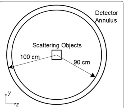
The linear accelerator simulation provided the angular distribution, energy spectrum, and the electron to x ray conversion rate for a typical linear accelerator pulse. The results from the linear accelerator simulation were used to simulate the ToF of x-ray photons scattering back from a set of objects (polyethylene boxes). The source was placed at the origin, the boxes were placed with their cen-tres at 50 cm intervals along the x axis, whilst the de-tector was set on the x= 0 plane. The detector was annular in shape, with inner radius of 90 cm and outer ra-dius of 100 cm. This ensured that the ToF of photons scattering from the same box led to a sharp pulse, rather than blurring the boundaries between box and it also al-lows easier analysis. The geometry of the simulations is il-lustrated in Figures 7 and 8.
The photons arriving in the annular detector have been histogrammed into 1/8 ns time bins, and plotted in Figure 9 on a log scale. The number of photons detected has been expressed as a percentage of the number of
incident photons. Error bars have been included assum-ing Poisson statistics. For this simulation, a delta pulse width was used.
The background shape of the plot results from photons scattering in the air and reaching the detector. The three peaks correspond to photons that scatter in each of the boxes before reaching the detector. Each peak has a sharp rising edge due to the scatter from the front edge of boxes, and then a longer tail which arises from the scattered photons becoming attenuated within the box. Each peak has been labelled on the plot.
This is the expected ToF information from three boxes if a laboratory source, with a very short pulse width, was used. In order to estimate the ideal response when using
Figure 7Illustration of simulated geometry.
a linear accelerator, its distribution was convolved using a number of ideal square wave pulses. The linear accel-erator was simulated as having two states, either on, 1, or off, 0, and had pulse widths of 0.1, 0.5, 1.0, 2.0, and 5.0 μs. An example of a square wave linear accelerator with a 1 μs pulse width has been plotted in Figure 10, along with a trapezoidal and triangular pulse shape.
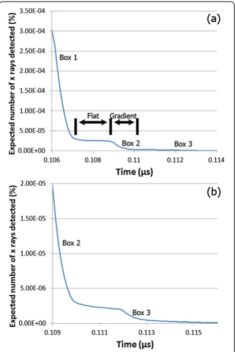
After convolving the pulses, as described above, with the ToF histogram in Figure 9, it was found that, as expected, the pulse width did not alter the resultant fall-ing and risfall-ing edges of the ToF histogram expected from an ideal linear accelerator. There are three features to the histogram after convolution; a rising edge, a falling edge, and a flat top joining them. All of the usable infor-mation is contained in the falling and rising edge. The falling edge of the simulated ToF histogram has been
plotted in Figure 11(a), for a 0.1μs pulse width. The ris-ing and fallris-ing edges correspondris-ing to each visible box have been identified in the plots. The rising edge of the ToF histogram is a vertical flip of the falling edge, in the ideal case, and contains the same features.
The plot includes several flat sections and gradients. The gradients arise due to the counts from each of the boxes, whilst the flat sections arise from the sections of air in between the boxes. The length of the boxes can be calculated by measuring the length of each gradient, whilst the distance between the boxes can be calculated by measuring the length of the flat sections. All three of the boxes can be seen in the edges; however the third box gives a very low expected signal. The third box can be seen more clearly when the falling edge is enlarged, as shown in Figure 11(b).
The initial gradient in Figure 11(b) is the counts due to second box, whilst the gradient that occurs at 0.112μs is due to the third box. Figure 11(b) shows that whilst the third box is visible in an ideal case, the expected signal is
Figure 10Example of a trapezoidal, triangular, and square pulse shape.
Figure 9ToF of photons scattering from 3 boxes.The source had a delta type pulse width.
1% of the maximum expected signal. In a real accelerator and detector system there will be noise present due to the electronics noise associated with the detector, the statis-tical fluctuations due to the finite number of x-ray pho-tons, and photons that might scatter off other objects or penetrate the shielding into the detector. Since the sta-tistical noise associated with x-ray photons follows a Poisson distribution, it is unlikely that the 1% signal will be above this noise level unless a very high initial flux was used in the accelerator pulse.
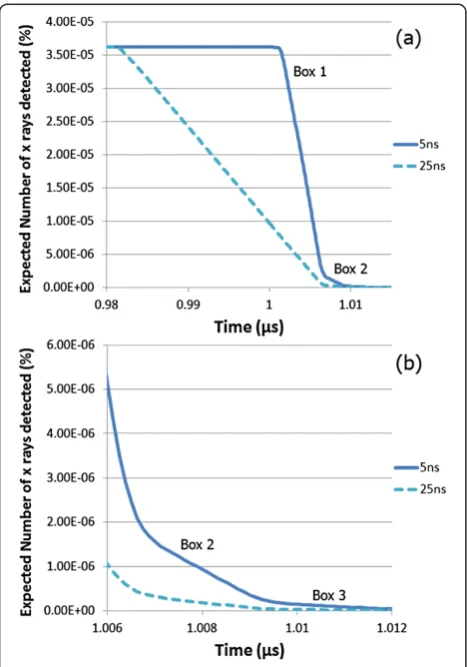
As described above, the pulse length does not have an effect on the expected detector response shape as the pulse length is a lot longer than the ToF of photons scat-tering in the objects. The usable information arises from the sharp rising and falling edge of the linear accelerator pulse. If the edges have a finite gradient and the pulse shape becomes trapezoidal, then this can cause the step shapes, seen in Figure 11(a), to lose their definition and the gradient of the edges to reduce in magnitude.
The plot presented in Figure 12(a) shows the falling edge expected from two different trapezoidal shapes, one
with a 5 ns rise time, and the other with a 25 ns rise time, and Figure 12 (b) shows an enlarged version.
The step features are still visible in Figure 12(a), how-ever, the gradients of the falling edges have decreased in magnitude. The gradient of the falling edge from approxi-mately 80% to 20% of the signal in the plot in Figure 11(a) was 3.28 × 10⁻⁴% per nanosecond. For a 5 ns rise time this has decreased to 5.87 × 10⁻⁵% per nanosecond and 1.24 × 10⁻⁵% per nanosecond for a 25 ns rise time. As the rise time increases, the falling edge gradient increases (but de-creases in magnitude) further. The distinction between air and box is removed due to the decreasing magnitude of these gradients. Moreover, the signal due to the boxes further away has reduced. In Figure 11(a) the initial falling edge drops to approximately 9% of its maximum before the gradient approaches 0 due to the air gap between boxes. With a 5 ns rise time this drops to approximately 4% and 1% for a 25 ns rise time, decreasing the signal-to -noise ratio.
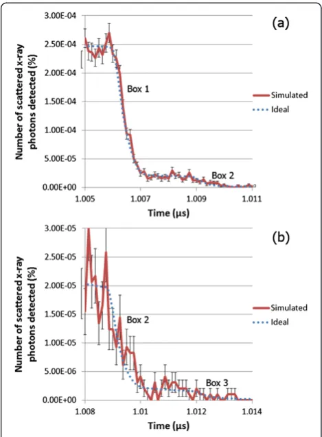
The results, so far, have given an ideal case. In order to get an indication of what the ToF response from a single linear accelerator pulse is, each photon that had been detected in the plot of Figure 9 was given a firing time be-tween 0 and 1μs drawn from a uniform random distribu-tion. The number of photons was chosen in order to model a 1 μs pulse correctly, with a square wave pulse shape, fired from a linear accelerator running at 125 mA. Increasing the current would increase the signal-to-noise ratio as more photons would be detected. The falling edge can be seen in the plot in Figure 13(a), whilst an enlarged falling edge can be seen in Figure 13(b), showing the con-tribution from the last two boxes only. The first two boxes are visible in the data; however it is difficult to measure where the third box starts due to the low photon count.
A large percentage of the detected photons in these simulations has been scattered from the front box only. This is due to the attenuation of the primary beam, causing fewer photons to be incident upon the rear boxes, and the attenuation (within the front box) of pho-tons scattering from the rear boxes. This leads to a lower signal from the rear boxes. In order to increase this sig-nal, these simulations were repeated, however, five boxes were used. Each box was 9 cm thick and centred at 25 cm intervals. This reduced the signal from the front box, and increased the number of steps in the edges.
The beam current was also increased in the simula-tions in order to increase the signal from the rear boxes. In a real life setting this is equivalent to increasing the current of the linear accelerator or performing repeated measurements of the same object. The data has been plotted in Figure 14(a) and Figure 14(b), and whilst the signal from the fourth box is larger at around 5 or 6 counts per time bin, the signal from the fifth box rarely gets above 1 detected count per time bin.
How these results can be used in next generation cargo screening systems
There is still a lot of work required to use the kind of signals in these preliminary results in the next gener-ation of cargo screening. The edges in the graphs would not be identified by human operators in a screening sys-tem. The signals would be used to reconstruct an image using mathematical techniques. For a single delta-type source and detector, a photon that is detected at time t must have scattered at some point on an ellipse defined by the source and detector positions, andt, assuming a single scatter occurs. Using a delta-type source, it is therefore simple to reconstruct an image based on calcu-lating the scatter points on these ellipses. For a square wave source, there is no longer a single ellipse for each timet, however there are only a finite number of ellipses that the photon could have scattered on. Mathematical image reconstruction techniques can be used to exploit this and reconstruct an image.
The results presented previously are indicative of an ideal detector response from an x-ray ToF CSI system. The results show that ToF information can still be recov-ered when a wide pulse is used, provided that the pulse
has a sharp rising and falling edge. In a real system, the x-ray beam would be swept over the container and the data would be combined to create a three dimensional image. Whilst the results presented are not directly transferrable to the next generation of cargo screening systems, they indicate that x-ray ToF CSI could be used for the next generation of cargo screening and that further research should be undertaken in the area.
Conclusions
Advantages of using x-ray ToF CSI
The use of ToF in conjunction with CSI allows the re-construction of interactions of individual photons as-suming the time of creation and initial trajectory are known and only single scatter occurs. The time of cre-ation is known only when a delta-type source is used, restricting the technique to laboratory settings. In these settings, the ToF from scattered photons produces sharp peaks corresponding to the position of different objects in the third dimension, as seen in Figure 9. Swee-ping the beam over the entirety of the objects un-der inspection allows three-dimensional images to be reconstructed.
Figure 13(a) Monte Carlo simulated falling edge of ToF using a linear accelerator, (b) enlarged version of the plot in Figure 13 (a).
X-ray cargo screening systems utilise linear accelerators to create photons. Unlike delta-type sources, the pulse is a square wave with a long flat top. The time of creation is lost if a linear accelerator is used, however ToF informa-tion can be recovered if the square wave has sharp edges. Using a linear accelerator, each object is represented by a step on the rising and falling edge of the detector re-sponse. This leads to double the information per pulse compared to delta-type sources, as both edges can be utilised. The results from the present work indicate that linear accelerators can be used for ToF cargo screening, removing the need to develop new sources with short pulse widths and decreasing time and cost of developing such a system. This has significant practical implications and indicates that the cost of a source for an x-ray ToF CSI system is therefore kept the same as for a transmis-sion system. The difference in cost between a traditional transmission system and a new ToF system is solely dependent on the detectors and associated electronics. The economic impact of implementing the United States’ 100% cargo screening laws has been well researched (see Martonosi et al., 2005, for example), and the economic cost must be taken into account when designing new screening technologies.
The use of a linear accelerator for scatter imaging also allows the two techniques to be integrated more easily in to a single imaging system. Currently, combined transmis-sion and scatter imaging systems use a single low energy (kV) source or separate low and high energy sources for scatter and transmission imaging, respectively. Using a single low energy source for transmission imaging leads to low penetration and is unsuitable for densely packed cargo. Using two (or more) sources requires separate shielding, power, control systems, etc. for each source increasing cost and weight. Using the same high energy linear accelerator to produce two dimensional transmission and three dimensional scatter images combines the benefits of the two systems whilst keeping costs low.
Using currently available linear accelerators for x-ray ToF CSI means the radiation dose to cargo is neither in-creased nor dein-creased when compared to conventional x-ray screening systems. The radiation to dose to human trafficking victims would therefore still be below inter-national guidelines.
There are some drawbacks to using ToF CSI as a cargo imaging system. Monte Carlo simulations of ToF experi-ments suggest that using a linear accelerator can provide useful information, however the limiting factor is the number of photons recorded. The low photon counts would lead to noise in the image. The linear accelerator simulated was set to 125 mA, increasing the current would increase the number of photons detected and in-crease the signal to noise ratio as seen in the Figure 14(a) and Figure 14(b).
The lack of penetration from CSI systems has also been highlighted in the results. Attenuation occurs within the objects, and signal from occluded objects is very low. The results given above relate to only one annular detector. Having several other detectors would increase the signal from occluded objects, however the electronics noise would also increase.
How the technology can help to reduce crime
There are two main benefits of using x-ray ToF CSI that could lead to crime reduction and increased security. Firstly, three dimensional images reduce the number of complex, overlapping objects in an image. Hence, suspi-cious objects are more easily identifiable in the object, thereby increasing detection rates. False positive rates should also decrease as a result, which means physical in-spection by unpacking containers can be targeted at truly suspicious containers. Since physical inspection rates will decrease, the time taken per inspection can increase, allowing a more meticulous inspection.
As the images become simpler to analyse, the time re-quired for analysis is reduced. This means more con-tainers can be screened at each port, using the same number of inspectors per system. Hence, the likelihood that a suspicious container is screened increases and likelihood of intercepting illegal items passing through the port increases.
A third, perhaps more minor, benefit comes from de-terrence. As technology improves, detection and inspec-tion rates increase, and criminals may be deterred from attempting to pass illegal items through ports. However, there is a chance this could lead to a displacement effect and criminals use alternative routes of importing illegal items.
Using CSI provides greater contrast for materials of lower atomic number and hence ToF CSI would still con-tain this high contrast, and would therefore highlight ob-jects such as cigarettes, drugs, and explosives in an image. Objects with high atomic number, such as weapons, would be seen in a highly scattering background, but would present a greater challenge in a low scattering background. The main drawback of using ToF CSI is the lack of penetration. Using high energy x rays maximises the penetration of the incident x rays, however the com-paratively low energies of the scattered photons is still the limiting factor. Containers packed with high density ma-terial could evade detection, as is the case with current screening methods.
Limitations of study and further work
resolution and electronics noise associated with them, which would increase the noise in the signal given. More-over, x-ray sources are not shielded absolutely and not all photons go through the collimator aperture. Photons produced in unwanted directions could penetrate the shielding and interact in the detector leading to increased noise levels.
Due to the preliminary nature of the work, the simu-lated geometry was simplistic and sparse. A more com-plex set of objects would create more scatter signals to be considered. Firstly, an increase in the number of objects under inspection would lead to an increase in multiple scatter which will lead to increased blurring between ob-jects. More objects could also lead to increased atte-nuation and reduced signal from occluded objects, as mentioned previously. It is important to stress that the aim for the resolution in the third dimension is not high (approximately 10 cm), due to the timing resolution achievable with current detectors. Whilst multiple scatter may blur the boundaries between objects, the immediate aim is to differentiate between the positions of objects ra-ther than recover fine detail in the third dimension. The problem due to attenuation will be the larger problem in the third dimension. If no photons are scattered back from occluded objects, then the objects will not be present in the image.
This paper describes preliminary simulations of a ToF CSI system, and the area for further work is abundant. The short term aim is to repeat these experiments in a real-life setting. Before this a number of intermediary steps must be undertaken. Firstly, measurements must be undertaken from a linear accelerator in order to ascertain the exact pulse shape and ensure that the edges are flat enough for a signal to be recoverable. Optimisation of de-tector placement and design is required to ensure max-imum signal is recovered. Moreover, suitable detectors must be identified and tested for timing resolution. Exper-iments will validate the results given by these simulations; however the results will be limited by the electronics noise, timing resolution of the detectors, and other noise sources. Building these into the simulations will give a direct comparison to the experimental results, allowing for full validation of the simulation results.
X-ray ToF CSI may provide limited three-dimensional information, signifying an improvement on the current CSI systems used for cargo screening, however, the chal-lenges to implementing such a system are numerous and significant extra work is required before such a system can be implemented.
The present work has introduced a technique to in-crease the efficiency and effectiveness of cargo screening. Techniques such as this are a necessary but not sufficient tool in the detection and deterrence of illegal, cargo based, trade. In parallel, to maximise the capabilities of
such technologies, the effectiveness of those tasked with monitoring containers visually should be examined by in-vestigating the psychology of vigilance.
Abbreviations
CSI:Compton scatter imaging; CT: Computed Tomography; FWHM: Full width at half maximum; PET: Positron Emission Tomography; ToF: Time of Flight; UNODC: United Nation Office on Drugs and Crime.
Competing interests
The study presented was undertaken as part of a studentship that was part funded by Rapiscan Systems Ltd.
Authors’contributions
NC participated in the design of the study, performed the simulations and drafted the manuscript. EM conceived of the study and participated in the design of the study. RS participated in the design of the study and helped to draft the manuscript. All authors read and approved the final manuscript.
Authors’information
NC is a PhD student in the Security Science Doctoral Training Centre at University College London. EM is Technical Director at Rapiscan Systems, Cargo Division. RS is the Joel Chair of Physics Applied to Medicine at University College London.
Acknowledgments
The authors would like to acknowledge Dr. Alick Deacon and Dr. James Ollier for their input during the project and for providing valuable
corrections for the manuscript. Dr Marta M. Betcke also gave invaluable input to the project, which the authors are grateful for. Funding for this project was provided through the Engineering and Physical Sciences Research Council Grant no: EP/G037264/1 as part of UCL's Security Science Doctoral Training Centre, and through Rapiscan Systems Ltd.
Author details
1
Department of Security and Crime Science, University College London, 35 Tavistock Square, London WC1H 9EZ, UK.2Rapiscan Systems, Victoria
Business Park, Prospect Way, Stoke-on-Trent ST8 7PL, UK.3Department of Medical Physics and Bioengineering, University College London, Gower Street, London WC1E 6BT, UK.
Received: 16 January 2013 Accepted: 2 June 2013 Published: 6 June 2013
References
Agostinelli, S, Allison, J, Amako, K, Apostolakis, J, Araujo, H, Arce, P, Asai, M, Axen, D, Banerjee, S, Barrand, G, Behner, F, Bellagamba, L, Boudreau, J, Broglia, L, Brunengo, A, Burkhardt, H, Chauvie, S, Chuma, J, Chytracek, R, Cooperman, G, Cosmo, G, Degtyarenko, P, Dell'Acqua, A, Depaola, G, Dietrich, D, Enami, R, Feliciello, A, Ferguson, C, Fesefeldt, H, Folger, G, et al. (2003). Geant4-a simulation toolkit.Nuclear Instruments and Methods in Physics Research Section A, 506(3), 250–303.
Basu, S, Kwee, TC, Surti, S, Akin, EA, Yoo, D, & Alavi, A. (2011). Fundamentals of PET and PET/CT imaging.Annals of the New York Academy of Sciences, 1228(2011), 1–18.
Chalmers, A. (2004). Single Sided X-ray inspection of vehicles using AS&E’s Z-Backscatter Van.SPIE Penetrating Radiation Systems and Applications V, 5199, 19–25. doi:10.1117/12.505800.
Chen, G. (2005). Understanding X-ray cargo imaging.Nuclear Instruments and Methods in Physics Research Section B, 241(2005), 810–815.
Dinca, DC, Schubert, JR, & Callerame, J. (2008). X-ray backscatter imaging.SPIE Optics and Photonics in Global Homeland Security IV, 6945. doi:10.1117/12.773334. Havocsope. (2013).The Financial Value of Criminal Activities. http://www.
havocscope.com/products/ranking/. Accessed 8 May 2013.
Kaluza, P, Kölzsch, A, Gastner, MT, & Blasius, B. (2010). The complex network of global cargo ship movements.Journal of the Royal Society Interface. doi:10.1098/rsif.2009.0495.
Knoll, GF. (2010).Radiation Detection and Measurement(4th ed.). New Jersey: John Wiley & Sons.
Kyle, D, & Liang, Z. (2001).Migration Merchants: Human Struggling from Ecuador and China(Working Paper, Center for Comparative Immigration Studies, University of California-San Diego).
Langeveld, WG, Brown, C, Christensen, PA, Condron, C, Hernandez, M, Ingle, M, Johnson, WA, Owen, RD, Ross, R, & Schonberg, RG. (2011). Performance Characteristics Of An Intensity Modulated Advanced X-Ray Source (IMAXS) For Homeland Security Applications.American Institute of Physics Conference Proceedings, 1336(2011), 705–710.
McLay, LA, & Dreiding, R. (2012). Multilevel, threshold-based policies for cargo container security screening systems.European Journal of Operational Research, 220(2), 522–529.
Martonosi, S, Ortiz, D, & Willis, H. (2005). Evaluating the viability of 100 per cent container inspection at America’s ports. In HW Richardson, P Gordon, & J Moore (Eds.),The Economic Impacts of Terrorist Attacks(pp. 218–241). Cheltenham, UK: Edward Elgar Publishing.
McNicholas, M. (2008). Drug Smuggling via Maritime Cargo, Containers, and Vessels. In M McNicholas (Ed.),Maritime Security: An Introduction
(pp. 189–224). Burlington, MA: Butterworth-Heinemann.
Rapiscan Systems Ltd. (2013).Rapiscan Eagle Portal Series Information Sheet. http://www.rapiscansystems.com/extranet/downloadFile/24_Rapiscan% 20Eagle%20Portal%20Series-InfoSheet.pdf. Accessed 29 January 2013. UNODC. (2010).World Drug Report 2010.
http://www.unodc.org/undoc/en/data-and-aalysis/WDR-2010.htm. Accessed 8 May 2013.
Wein, LM, Wilkins, AH, Bajeva, M, & Flynn, SE. (2006). Preventing the importation of illicit nuclear materials in shipping containers.Risk Analysis, 26(5), 1377–1393.
World Shipping Council (2012).Benefits of Liner Shipping. http://www. worldshipping.org/benefits-of-liner-shipping. Accessed 2 January 2013. Zentai, G. (2008). X-ray imaging for homeland security.IEEE International
Workshop on Imaging Systems and Techniques. doi:10.1109/IST.2008.4659929.
doi:10.1186/2193-7680-2-2
Cite this article as:Calvertet al.:Preliminary Monte Carlo simulations of linear accelerators in Time-of-Flight Compton Scatter imaging for cargo
security.Crime Science20132:2.
Submit your manuscript to a
journal and benefi t from:
7Convenient online submission 7Rigorous peer review
7Immediate publication on acceptance 7Open access: articles freely available online 7High visibility within the fi eld
7Retaining the copyright to your article