An efficient geo-routing aware MAC protocol
for underwater acoustic networks
Yibo Zhu
*, Zhong Zhou, Zheng Peng, Michael Zuba, Jun-Hong Cui
Department of Computer Science and Engineering, University of Connecticut, Storrs, CT 06269, USA
Abstract
In this paper, we propose an efficient geo-routing aware MAC protocol (GOAL) for underwater acoustic networks. It smoothly integrates self-adaptation based REQ/REP handshake, geographic cyber carrier sensing, and implicit ACK to perform combined channel reservation and next-hop selection. As a result, it incorporates the advantages of both a geo-routing protocol and a reservation-based medium access control (MAC) protocol. Specifically, with its self-adaptation based REQ/REP, nodes can dynamically detect the best next-hop with low route discovery cost. In addition, through geographic cyber carrier sensing, a node can map its neighbors’ time slots for sending/receiving DATA packets to its own time line, which allows the collision among data packets to be greatly reduced. With these features, GOAL outperforms geo-routing protocols coupling with broadcast MAC. Simulation results show that GOAL provides much higher end-to-end reliability with lower energy consumptions than existing Vector-Based Forwarding (VBF) routing with use of a broadcast MAC protocol. Moreover, we develop a theoretical model for the probability of a successful handshake, which coincides well with the simulation results.
Keywords: geographic cyber carrier sensing, geo-routing, MAC, self-adaptation, underwater sensor network
Received on 5 January 2011
Copyright2011 Zhuet al., licensed to ICST. This is an open access article distributed under the terms of the Creative Commons Attribution licence (http://creativecommons.org/licenses/by/3.0/), which permits unlimited use, distribution and reproduction in any medium so long as the original work is properly cited.
doi: 10.4108/icst.trans.mca.2011.e6
1. Introduction
Underwater acoustic network is a promising technique that could connect underwater vehicles, sensor nodes, and other devices working in an underwater environmentvia
acoustic channels. It can be used to collect oceanographic data and monitor oceanic volcano activity or oil/gas fields [1–3]. Although it is a class ofad hocnetworks, the routing and medium access control (MAC) protocols for terrestrial
ad hocnetworks cannot serve it. This is because of its long signal propagation delay, narrow channel bandwidth, and high node mobility. These issues also provide challenges in designing efficient routing and MAC protocols for underwater acoustic networks [1–5].
In underwater acoustic networks, traditional routing protocols such as AODV [6] do not work because their costly route discovery process is unsuitable in long-delay underwater environments. Geo-routing protocols, such
as VBF [7], VBVA [8], and DBR [9], are preferred here. These protocols do not need dedicated route discovery and forward packets directly based on the nodes loca-tions. Since location information is indispensable for many aquatic applications [10–14], these protocols do not cause much extra cost and are very efficient from the routing perspective.
However, geo-routing protocols [7, 9] are usually based on the broadcast nature of the underlying acoustic channel. It is highly possible that multiple nodes are selected as the next-hop, which can lead to collisions if all of these next-hop candidates relay the packet. Although the self-adaptation methods such as those in [7,9] narrow down the size of the candidate set to some extent, the collision probability is still very high without proper MAC design and optimization.
Existing MAC protocols for underwater acoustic net-works, such as R-MAC [15], UWAN-MAC [16], and T-Lohi [17], are usually based on channel reservations.
*Corresponding author. Email:yibo.zhu@engr.uconn.edu
In these protocols, senders and receivers interact with each other to reserve the channel for data communica-tions. Before the channel reservation process, sender must know the exact receiver. Unfortunately, it cannot be sat-isfied by current geo-routing protocols since a node can-not know its next-hop node beforehand in the stateless routing protocol. For example, in R-MAC, a node reserves a channel by measuring the propagation delay and mapping the slot at the sender side to the receiver side, which is not compatible with the geo-routing proto-cols that cannot provide the next-hop information. Therefore, a new MAC protocol which can effectively suppress collisions and can be smoothly combined with geo-routing protocol is highly desirable.
In this paper, we propose an efficient Geo-rOuting Aware MAC protocoL (GOAL) for underwater acoustic networks which smoothly integrates self-adaptation based REQ/REP, geographic cyber carrier sensing, and implicit ACK to find the next-hop node and perform channel res-ervation at the receiver side. Utilizing self-adaptation based REQ/REP, a forwarder can determine the best next-hop with little route discovery cost. By adopting geographic cyber carrier sensing, collisions among the data packets are almost eliminated. With implicit ACK strategy, control messages are significantly reduced and thus fewer collisions occur among control packets. With these techniques, GOAL is energy-efficient and provides high end-to-end reliability. Another remarkable feature is that GOAL can work in mobile underwater acoustic networks with localization services such as SLMP [14].
The rest of this paper is organized as follows.Section 2 briefly discusses the related works. Then, GOAL is pre-sented in detail in Section 3. After that, a theoretical model is developed for the probability of a successful handshake inSection 4. Subsequently, simulation results and discussion are shown inSection 5. At last,Section 6 provides our concluding remarks and future work.
2. Background and related work
In this section, we will first review related works on geo-routing protocols in underwater acoustic networks and demonstrate the disadvantages in collision resolutions. We will then review MAC protocols for underwater acoustic networks and their differences from our work.
In underwater acoustic networks, nodes communicate
via acoustic channels with long propagation delay and therefore take more time and consume more energy to perform route discovery. Luckily, a couple of localization algorithms [11–14] have been designed for underwater acoustic networks, which make geo-routing possible. Geo-routing protocols which are based on the nodes location have been gaining significant attention because they perform stateless routing which allows their routing cost to be very low. In VBF [7], for example, packets are forwarded along the routing pipe from the source to the
destination. All nodes within the routing pipe will partic-ipate in the packet forwarding process. In DBR [9], a depth-based geo-routing protocol, packets are forwarded to nodes with less depth and finally arrive at the sink nodes deployed on the sea surface. A more recent routing protocol is VBVA [8], which is based on VBF and incor-porates the void avoidance capability. In all these proto-cols, a node does not explicitly choose the next-hop but cooperates with its neighbors to determine the best relay node(s) according to some self-adaptation schemes.
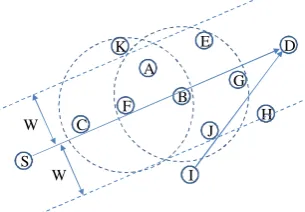
The basic idea of self-adaptation is as follows. When an eligible node, one that is nearer to the destination than the previous hop, gets a data packet, it starts to back off according to its location before forwarding the packet. The self-adaptation scheme tries to guarantee that a bet-ter relay node backs off for a shorbet-ter time so that the best relay node ends backoff and then forwards data packet first. For example, as shown inFigure 1, node C and node K are ineligible because the former’s position is worse than that of node F and the latter lays out of the pipe area from the source node S to the sink node D. Then, only node A and node B are eligible to forward. Comparing with node A, node B is closer to the vector from source node S to sink node D,and node B is closer to the sink node D than other neighbors of forwarder F. Thus, according to the self-adaptation scheme, the backoff time of node B is shorter than that of node A after receiving the DATA packet from node F. As a result, node B first forwards the DATA packet. By overhearing the forward-ing, other nodes, such as node A, cancel the backoff and do not forward the packet any further. In this proce-dure, several optimal relay nodes1 can forward first and other nodes are suppressed by the overheard forwarding. As this procedure is repeated, the packet will get closer and finally arrive at the sink node.
Although such a self-adaptation scheme can improve the system’s performance to some extent, it cannot pre-vent MAC collision when there are two or more adjacent nodes forwarding packets at the same time. As shown in Figure 1, if node J happens to forward the DATA packet
S
D
F A
B C
G H E
J W
W K
I
Figure 1. VBF: a self-adaptation based geo-routing protocol.
1Some nodes might have already forwarded the data packet
for node I when node B also relays the DATA packet, col-lision might occur at the common neighbors of nodes B and J, and therefore the DATA packet might not be fur-ther forwarded. This harms the end-to-end reliability of the routing protocol. Additionally, the dropped packets waste plenty of energy, i.e. they are not energy-efficient. In order to further improve the performance of geo-routing protocols, effective collision resolution schemes should be employed, which are usually implemented in the MAC protocols. MAC protocols have been widely investigated for underwater acoustic networks in the last few years. In FAMA [18], RTS/CTS and carrier sensing are combined to avoid collision. However, it is not energy-efficient because the REQ/REP packet is very long and consumes lots of energy to transmit. Slotted-FAMA [19], a modified Slotted-FAMA, tries to improve the energy-efficiency problem by slotting the time and send-ing both control and data packets at the beginnsend-ing of a slot. In this way, the length of an RTS/CTS packet is not determined by the maximal propagation delay as that in FAMA and therefore is much more energy-efficient. However, the RTS/CTS handshake requires the routing protocol to explicitly provide the next-hop, i.e. it cannot act as the MAC protocol for self-adaptation based geo-routing protocols.
COPE-MAC [20], a novel RTS/CTS-based MAC pro-tocol, enables nodes to perform reservations in parallel such that nodes can send multiple DATA packets in one RTS/CTS/DATA/ACK round. For long-delay featured underwater acoustic networks, COPE-MAC is energy-efficient and can significantly improve the throughput. Unfortunately, similar to Slotted-FAMA, it also requires the explicit next-hop and therefore cannot be coupled with self-adaptation based geo-routing protocols.
In T-Lohi [17], a short tone message is used to reserve the channel to send data. However, even though a node does not receive any tone during a contention period, it cannot ensure that there is no collision at the receiver side. In other words, it still suffers from the hidden termi-nal problem and cannot effectively avoid the collisions.
R-MAC [15] consists of three phases. In the first phase, each node measures the propagation delay to its neigh-bors. In the second phase, each node reserves a receiving slot at the receiver side and then the receiver confirms if the reservation is collision-free. This phase can make sure that there is no collision at the receiver side for the data packet. In the last phase, each node follows the reserva-tion in the second phase to transmit the data packets. An explicit receiver address is needed in phase two for the channel reservation, and therefore R-MAC cannot work with self-adaptation based geo-routing protocols as well.
Unlike other reservation-based MAC protocols, UWAN-MAC [16] does reservationviaone-way commu-nication. Assuming the delay between neighbors does not vary, each node piggybacks the relative sending time of
the next packet in current packet. As a result, a node knows when it will receive the next packet. However, such a one-way handshake cannot solve the hidden terminal problem. Therefore, collision is still heavy in multi-hop networks. In addition, UWAN-MAC requires nodes to foresee the exact sending time of the next packet, which is unpractical in self-adaptation based geo-routing protocols.
Different from above works, GOAL, the new approach in this paper, smoothly integrates the self-adaptation scheme and MAC reservation techniques. It first employs the self-adaptation scheme to do handshaking and finds the next-hop. Similar to implicitly finding the best relay in self-adaptation based geo-routing protocols, the cost of selecting the next-hop is low in our protocol. Addi-tionally, the receiving slot is reserved based on the geo-graphic information during the handshake, and then the DATA packet can be forwarded without collision. Thus, GOAL finally avoids more collisions while keeping a low routing cost.
3. Description of GOAL
In this section, we will discuss our new GOAL, which is reservation-based and can smoothly integrate with any known geo-routing protocols with self-adaptation. For instance, if GOAL adopts the self-adaptation scheme of VBF, its functionality is equivalent to that of a reserva-tion-based MAC protocol coupling with VBF. We first present the basic idea of GOAL. Then, we describe its three key components, self-adaptation based REQ/REP handshake, geographic cyber carrier sensing, and implicit acknowledgement. Specifically, we apply the self-adapta-tion scheme of VBF to GOAL as a special case in the description. (Note that GOAL can be used with any self-adaptation scheme.) After that, we will provide an example to show the overall working process of GOAL with detailed analysis.
3.1. Basic idea
mapping the neighbors’ sending and receiving slots to a node’s own time schedule.
As shown inFigure 2(a), when sending a packet, node S piggybacks the transmission time T2 and the relative
sending time T of the next packet. After receiving this packet, node R can calculate the receiving time of the packet, i.e. it maps the sending time of the packet at node S to its time schedule line. Specifically, the interval between the time when node S sends the first and second packet isT. Assuming that the propagation delay between nodes R and S does not change much during the coming time periodT, the interval between the time points when node R begins to receive these two packets is still T. Therefore, after node R finishes receiving the first packet, it knows that it will receive next packet during time slot [T T1, T T1+ T2], where T1 and T2 are the
trans-mission times of the first and second packet, respectively. Note that the time slot is expressed by relative time and can be easily converted to absolute time.
The method of mapping the receiving time is illustrated inFigure 2(b). When node R sends the first packet, which has a transmission time ofT1, it then notifies its neighbors
including node N that it will receive the next packet after a time period ofT0. Suppose that node N knows that the
propagation delay between itself and node R is Tprop.
After completely receiving the first packet, node R knows that there will be a collision at node R if it emits any packet signal during [TT1 2Tprop, T0 T
1
2Tprop+T2], where T2 is the transmission time of the packet which node R will receive. Therefore, in order to avoid the collision at node R, node N must make sure that the sending interval does not overlap with time slot [T0T
12Tprop, T0T1 2Tprop+T2] when it
sends out any packet.
Applying these two mapping schemes, a node can map its neighbor’s sending and receiving time period to its own time schedule line to avoid collisions when transmit-ting a DATA packet.
3.2. The GOAL protocol
The GOAL protocol consists of three parts: self-adapta-tion based REQ/REP handshake, geographic cyber
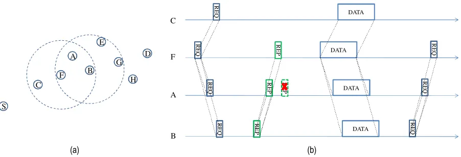
carrier sensing, and implicit acknowledgement. As described in Section 3.1, self-adaptation based REQ/ REP handshake and geographic cyber carrier sensing are used to determine the optimal next-hop and reserve chan-nel for DATA packets. In addition, implicit acknowledge-ment is imported to reduce the number of control messages. The details of these parts are provided as fol-lows based on the network topology shown inFigure 1.
Self-adaptation based REQ/REP handshake. When the
cur-rent forwarder F intends to send out a DATA packet, it first selects a qualified sending time to broadcast a REQ{PS,PF,PD,T,TDATA} packet.Viathe REQ packet,
node F tells its neighbors that it will send the DATA packetT time later2 and the corresponding transmission time isTDATA. It also provides the location of the source,
current forwarder, and the destination, which arePS,PF,
and PD, respectively.
After receiving REQ, neighbors of node F then know that they will receive the DATA packetT TREQtime later
(by applying the method of mapping neighbor’s sending slot), where TREQ is the transmission time of the REQ packet. Then, the neighbors who have a better location than that of node F start to back off according to the self-adaptation scheme of VBF. Once a node terminates the backoff process, it will send node F a REP{Pthisnode, T0, T
DATA} packet, where Pthisnodeis the location of this
node andT0is the relative time that it will send a DATA
packet. Due to the broadcast feature of acoustic medium, part of node F’s neighbors, which might still be in the back-off state, can overhear the REP packet. Then, they cancel the backoff process because the overheard REP implies that there is a better relay. Finally, node F decides the next-hop according to the received REP packets. If it does not receive any REP, it waits for a random time period and tries to resend the REQ. Otherwise node F must receive at least
(a) (b)
S R
T T T1
RE
Q
T2 DATA
DATA
RE
Q
N R
T1 T2
T’
DATA
RE
P
R
EP
DATA
T’-2Tprop
Figure 2. (a) Mapping neighbor’s sending slot and (b) mapping neighbor’s receiving time slot.
2Note that T must be bigger than double the maximum
one REP packet from its neighbors. In this case, it sets the next-hop as the one with the shortest adaptation time, which node F can for use the location information in REPs to calculate again. Once the pre-scheduled DATA sending time comes, node F sends the DATA packet to the selected next-hop.
As an improvement, multiple DATA packets to the same sink node can be transmitted in one packet train [19], and therefore REQ/REP handshake could perform reservation for multiple DATA packets in one round. This strategy can clearly enhance the efficiency of handshake.
Geographic cyber carrier sensing. In underwater acoustic
networks, it is difficult for nodes to completely avoid colli-sions due to the long propagation delay. In order to address this issue, nodes in GOAL apply the geographic informa-tion and the two mapping methods inSection 3.1to map neighbors’ packet sending and receiving slots to their time schedule line. In this way, nodes can figure out when they can send a packet and when they cannot. This is similar to carrier sensing, and therefore we have named it geographic cyber carrier sensing. With geographic cyber carrier sens-ing, the collisions at neighbors can be greatly alleviated if the selected packet sending time does not overlap with any reserved slot in its time schedule line.
Specifically, after receiving the REQ packet, a node knows that it will receive the DATA packet during [T TREQ,T TREQ+TDATA] by applying the method of mapping neighbor’s sending time slot, where TREQ
stands for the transmission time of REQ packet. Then, this node converts the time slot to absolute time and inserts it into its time schedule line.
The REP packet has twofold functionalities: responding the REQ packet and notifying neighbors to avoid colli-sions. On one side, with the REP packet from node B, the sender of REQ knows that node B is a potential next-hop. On the other side, based on the information in REP packet, other neighbors of node B can evaluate the propa-gation delayTpropbetween themselves and node B. The
evaluation method is to use propagation speed to divide the Euclidean distance. Then by applying the method of mapping neighbors’ receiving time slot, this node will know that there will be a collision at node B if it sends packet during [T0T
REP2Tprop, T0TREP
2Tprop+T2], whereTREPis the transmission time of REP
packet. To avoid collisions, this node should not emit any packet signal during this period. Note that the propagation delay measure method might introduce an error because the acoustic signal is transmitted along a bent path and the nodes are mobile. In order to tolerate this error, guard time Tguardis introduced, i.e. the propagation delay is in
range [TpropTguard,Tprop+ Tguard]. Thus, the time
per-iod becomes [T0T
REP2Tprop2Tguard, T0 TREP
2Tprop+ TDATA+ 2Tguard].
Based on geographic cyber carrier sensing, nodes can obtain their neighbors’ sending and receiving schedule
after the REQ/REP handshake. By recording the sched-ules in their time schedule line, nodes can conveniently choose a qualified time to send packet.
Implicit acknowledgement. In terrestrialad hocnetworks,
REQ/REP/DATA/ACK can substantially improve the reliability of one-hop transmissions. However, if this scheme is applied in underwater acoustic networks, there are more collisions among control packets because of low bandwidth and long propagation delay. A possible way to address these challenges is to adopt an implicit acknowl-edgement scheme to reduce the number of control pack-ets. Specifically, if the node that receives the DATA packet is not the destination, it must send REQ to determine the next-hop within a certain time. Because the previous hop is still within the one-hop range with a high probability, it can also overhear the REQ. Based on this heuristic rule, REQ is revised to include the packet identifier (PID) of the DATA packet. As a result, the previous hop can con-firm that the DATA packet is successfully forwarded.
For the destination node, it explicitly acknowledges the DATA packet using an ACK packet. In addition, a node will send an explicit ACK packet without a backoff if it receives a REQ when both of the following conditions are met: (i) the location of this node is better than the sender of REQ; (ii) this node has received the DATA packet for which the REQ packet requested.
For any node, if it does not receive an implicit acknowl-edgement or ACK packet within certain time after sending out the DATA packet, it will initiate a new REQ/REP/ DATA round to retransmit the DATA packet. Although retransmission can improve the transmission reliability, the maximum number of times that retransmission can occur should not be infinite. This is because it will intro-duce more delay and energy consumption. Therefore, we define the number of maximum retransmission times as a tradeoff. Specifically, one node can transmit and retransmit a DATA packet at most the number of maxi-mum retransmission times, where a retransmission is caused by having failed to overhear the corresponding REQ packet or an ACK packet. If the number of maxi-mum retransmission times is exceeded, the node should give up trying to resend the DATA packet.
3.3. An example of GOAL
In the example, the network topology is shown as Figure 3(a). Node F tries to forward the DATA packet from source node S to destination node D. Following the GOAL protocol, node F selects a qualified sending time to broadcast a REQ{PS, PF, PD, T, TDATA, PID}
time later. Note that node C will discard this REQ because its location is worse than that of current forwarder node F. Therefore node F’s neighbors, except node C, start to back off according to the self-adaptation scheme in VBF. Similar to VBF, when node B first exits the backoff state, it sends a REP{PB,T0,TDATA} packet to node F. By
over-hearing the REP packet from node B, node A realizes that there is a better relay and cancels the backoff. Additionally, based on the information in the REP packet, node A can evaluate TBA, which denotes the propagation delay
between node B and node A. Thus, node A will not send any packet during time interval [T0T
REP2TBA
2Tguard, T0 T
REP2TBA+ TDATA+ 2Tguard]. As
well, node F finds out that the next-hop could be node B after receiving the REP packet. When the scheduled DATA packet sending time comes, node F sends the DATA packet to node B since node B is the optimal one. Later on, node B tries to forward the DATA packet and sends a REQ{PS,PB, PD, T, TDATA, PID} packet to do the handshake. After
receiving this REQ packet, node F knows that the forward-ing is successful and then prepares to forward the other DATA packets.
3.4. Properties of GOAL
In GOAL, nodes apply the self-adaptation scheme in the REQ/REP handshake process to determine the next-hop. This procedure is similar to the general self-adapta-tion based geo-routing protocol for data packets. Since a REQ/REP packet is much shorter than a DATA packet, the probability of collision among REQ/REP packets in GOAL is much lower than that among DATA packets in self-adaptation based geo-routing protocol. Note that the use of geographic cyber carrier sensing allows DATA packets in the GOAL protocol to be almost collision-free, and the entire collision probability is accordingly lower than that in self-adaptation based geo-routing protocols. As a result, GOAL provides a higher end-to-end reliability than self-adaptation based geo-routing protocol coupling with broadcast MAC.
As discussed above, GOAL introduces MAC collision among short REQ/REP packets while avoiding collision among long data packets. As a result, the collision prob-ability is reduced. It is clear that the collision among long DATA packets wastes more energy than the collision among short ones, and thus GOAL requires less energy consumption for packet delivery than self-adaptation based geo-routing protocols plus broadcast MAC.
However, in order to achieve the above desirable features, GOAL incurs a longer delay. As explained in Section 3.2, nodes schedule the sending time of a DATA packetTtime later after sending the REQ packet, where
T is at least the maximum backoff time plus double the maximum propagation delay. Moreover, due to implicit acknowledgement strategy, nodes will also wait for more than one round trip time. In addition, nodes in GOAL will perform retransmission if any failure occurs during the forwarding procedure, which will also increase the delivery delay. Therefore, the delivery delay in GOAL is higher than self-adaptation based geo-routing protocols plus broadcast MAC.
4. Analysis of probability of successful handshake
In this section, we theoretically explore the probability of a successful handshake in GOAL.
4.1. Notations
In this section, we define the terms in the analysis as follows.
TI: The given node maps the arrival time points of all
neighbors’ DATA packets to its own time schedule line. Then,TI is the length of the interval between
the arrival time points of two successive DATA pack-ets on the time schedule line.
T0I: The given node maps the scheduled sending time of all neighbors’ DATA packets to its own time sche-dule line. Then,T0I is the length of interval between the sending time points of two successive DATA packets on the time schedule line.
(a) (b)
S
D
F A
B C
G H E
DATA DATA DATA
RE
P
RE
P
R
EQ
RE
Q
RE
Q
F
B C
A
RE
Q
RE
P
RE
P
DATA
RE
Q
R
EQ
R
EQ
TD: Transmission time of the DATA packet.
Tc: Transmission time of the control packet (both REQ packet and REP packet).
n: The average number of neighbors of each node.
k: The average number of neighbors which reply a REP packet to the sender of a REQ packet based on the self-adaptation algorithm used by GOAL.
k: The traffic rate of DATA packets generated by each node.
kD: The real traffic rate of DATA packets that each node
sends to the channel.
Pc: The probability that the control packet is
transmit-ted successfully.
Pr: The probability that the requested time slot does not
overlap with any existing reserved slot on the time schedule line.
~
PH: The probability of the successful handshake.
4.2. Protocol simplification and assumptions
In GOAL, whenever the MAC layer gets a DATA packet from the upper layer, it will cache this DATA packet if it is forwarding another DATA packet in a REQ/REP/ DATA round. After transmitting the current DATA packet successfully, the node starts a new round to trans-mit the next DATA packet. To simplify the analysis, we revised GOAL such that a REQ/REP/DATA round for different DATA packets can be overlapped. Specifically, when a node is forwarding a DATA packet in a REQ/ REP/DATA round, it will cache the DATA packet from the upper layer and send a REQ to perform reservation for the DATA packet in the coming interval between DATA packets. Additionally, retransmissions will no longer happen. In other words, if REQ/REP handshake fails or a DATA packet is transmitted unsuccessfully, the DATA packet will be dropped. We also make the follow-ing assumptions throughout the analysis part of this paper.
(i) Similar to existing works [21–23], packet error rate is not considered in the model. In other words, a packet is dropped only if there is a collision.
(ii) The traffic at every node follows a Poisson process with samekparameter and the DATA packets are of the same length.
(iii) The length of the REQ packet is same as that of the REP packet.
(iv) Relay traffic is not considered, i.e. all nodes only do one-hop transmission.
(v) As described before, GOAL employs implicit ACK and the ACK packet is only sent by the sink node. Without relay traffic, there are few ACK packets in the networks. Therefore, we reasonably ignore ACK packets in the analysis.
(vi) A multi-hop network scenario is considered in the analysis. Accordingly, the analysis also involves the interferences incurred by hidden terminals, which is an important issue but ignored by most of the existing analysis works on MAC protocols.
4.3. Analysis
In this part, we deduce PH~ by analyzing the handshake process between sender S and its neighbors Ri(1i
n), where node S is an arbitrary node in the network. In GOAL, as illustrated inFigure 4, every node records the time slots when its neighbors receive or send DATA packets. To avoid the collision with DATA packets, con-trol packets (both REQ and REP) are transmitted during the interval between these time slots.
Although the arrival time of the DATA packet follows a Poisson process, the sending time of the DATA packet and the control packet no longer follows the Poisson pro-cess due to the schedule strategy in GOAL. However, because every DATA packet is preceded by a REQ packet and the REQ is sent immediately during the next available interval after a DATA packet arrives, the probability that
Nccontrol packets are sent by node Riand its neighbors,
except node S, during a given interval of lengthT0Iequals the probability that Nc DATA packets arrive during the
same time period. Thus, this probability still can be eval-uated by utilizing the Poisson process. Therefore, if T0I
and Ncare fixed, we can obtainPNc as
P Nð c¼ncÞ ¼
kcncekcT
0
I
nc! ; ð1Þ
wherekcis the traffic rate of control packets sent by node
Riand its neighbors, except node S, totalnnodes. Since
the traffic of control packets consists of REQ traffic and REP traffic, we can obtain
kc¼n kREQþkREP
: ð2Þ
Note that every DATA packet is preceded by a REQ packet, which implies REQ packets are subject to the same Poisson process as the input traffic. Therefore, we havekREQ=k. RegardingkREP, it is related tokREQ.
Spe-cifically, due to collisions, a REQ packet correctly arrives at node Ri with probability Pc. After getting the REQ
packet, node Richecks if the requested time slot overlaps
with any existing reserved time slot for DATA packets. If there is no overlap, it will reply a REP packet. Otherwise, it will discard the packet. According to the self-adaptation scheme,kout of thenneighbors of node S will reply the REP packet on average, i.e. each neighbor replies with probabilityk/n. Additionally, considering that each node is a potential REP replier of its nneighbors, we can get
kREP¼n k
where Pr is the probability that the requested time slot
does not overlap with any existing time slot for DATA packets. It can be evaluated as
Pr¼e2TDnk: ð4Þ
Substituting equations (4) and (3) into equation (2), we have
kc¼nð1þkPcPrÞkREQ: ð5Þ
Based onPNc, we can calculate the probability of event
A, which denotes the event that a REQ packet sent by node S collides with any control packets at node Ri.
According to the strategy in GOAL, the sending time of control packets approximately follows a uniform distri-bution. If there areNccontrol packets sent or received by
Ri in the interval of length T
0
I, excluding the control
packets from node S because there is no collision among the control packets sent by node S, then the collision probability of event A is
P AjNc¼nc;T
0
I¼T
¼ 1 2Tc
T TD
nc
: ð6Þ
Note that the handshake is successful as long as node S receives a REP packet from any neighbor. Recall that on average there are k potential repliers according to the self-adaptation scheme. Accordingly, we can calculate the probability of the event H, which represents the suc-cessful handshake,viaequation (7).
P HjNc¼nc;T
0
I¼T
¼1 1P AjNc¼nc;T
0
I¼T
k
:
ð7Þ
Then, considering the distribution ofNc, we can get
PHjT0I¼T¼X
1 nc¼0
1 1P AjNc¼nc;T
0
I¼T
k
:
ð8Þ
From equation (8), we can see that we still need to figure out the distribution of T0I to get PH~ . Although
TIfollows an exponential distribution,T
0
Idoes not follow
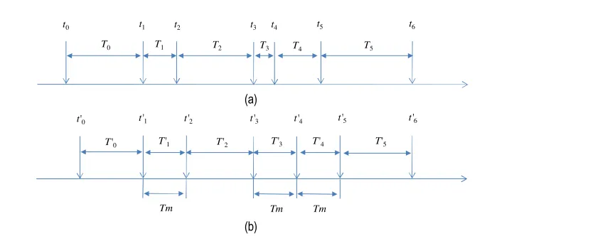
the exponential distribution anymore due to the schedule strategy in GOAL. As shown inFigure 5, for example, the
ithpacket arrives atti, and the duration of interval [ti,ti+1]
is Ti. After being scheduled, the sending time of the ith
packet becomes t0i, and the interval betweent0i and t0iþ1
isT0i. During this procedure, the interval length between DATA packets is adjusted to be at leastTm(Tm TD).
For a given interval sequenceTi(0il+ 1), there
are two conditions for that lsuccessive intervals T1 Tl
are adjusted to Tm but Tl+1 is reduced to an interval
longer than Tm. One is that T0 should be long enough
to allowt01¼t1. Here,t01 ¼t1 means the scheduled time t01 is not affected by schedule scheme in GOAL. And the other is
Pj
i¼1
TijTm for 1jl
Xlþ1
i¼1
Ti>ðlþ1ÞTm
: ð9Þ
Note that allTifollow an exponential distribution with
the samekdcparameter, wherekdcis the total traffic rate of
DATA packets sent by any given node, its neighbors, and hidden terminals. Since the time slots confirmed by REP packets might overlap with the slots requested by REQ packets, some slots are not successfully reserved. Specifi-cally, as long as overhearing a REP packet confirms an overlapped slot, the sender of the REP packet will remove the slot it intends to reserve on its time schedule time and try to reserve later. Therefore, we will overestimate the traffic rate of DATA packet if counting all time slots reserved by control packets in. To avoid this case, we approximate kdc as the sum of the traffic rate of DATA
packets sent by this node, the traffic rate of DATA packets sent by all neighbors, and the traffic rate of non-over-lapped DATA packets sent by hidden terminals. These three parts correspond to the three items in equation
DATA DATA
S R1
R2
DATA DATA
DATA
DATA
DATA
DATA
DATA
TI TD
RE
Q
R
EQ
Tc
(10), respectively. For the last item, we resort to a constant factora, which can be trained with the simulation data, to obtain the traffic rate of non-overlapped DATA packets since it is complicated to model the probability of the overlapped packets. Therefore,kdccan be expressed as
kdc¼kDþnkDþankkD¼ð1þnþankÞkD: ð10Þ
In equation (10), since a node will send out a DATA packet only if the handshake is successful,kDcan be
eval-uated by the following equation.
kD¼P~Hk: ð11Þ
Based on the distribution ofTiand the two conditions,
we can calculate the probabilityP L¼ljt1¼t
0
1
ofl suc-cessive intervals are all adjusted to intervals of lengthTm
as
P L ¼ljt1¼t01¼
Z Tm
0
Z 2TmT1
0
Z lTmP
l1
j¼1
Tj
0
Z 1
lþ1
ð ÞTmP l
j¼1
Tj
kdcekdcTm
lþ1
dTlþ1dTl dT2dT1
¼kdcleðlþ1ÞkdcTm
Z Tm
0
Z 2TmT1
0
Z lTmP
l1
j¼1
Tj
0
dTl dT2dT1:
ð12Þ
Note that equation (12) also denotes the probability that the (l + 1)th interval is long enough such that the arrival time of the next packet will not be adjusted. Thus, eachTl+1is actually one case ofT0. Then, we can get
P t1¼t
0 1 ¼X 1 l¼1
Pl: ð13Þ
With P t1¼t
0
1
and equation (12), we can calculate
dl(T), the probability that an interval of length T> Tm
is reduced to the interval of length Tm among a given l
successive adjusted interval.
dlð Þ ¼T P t1 ¼t
0
1
Xl
i¼c
kleðlþ1ÞkTm
Z LU1
0
Z LU j
0
Z Tþ
Ti¼T
Z LU h
0
Z LU l
0
dTl dTh dTi dTj dT1; ð14Þ
where !0+and
c¼ T Tm l m
LUh¼hTmT P
h2
b¼1 Tb
LUj ¼
jTmPj 1
b¼1Tb ifcij
iTmT Pjb¼11Tb otherwise
( : ð15Þ
Furthermore, we can calculate the probability of inter-val of lengthT(T >Tm) is adjusted toTm as
dð Þ ¼T P t1 ¼t01X1
l¼2dlð ÞT : ð16Þ
With d(T)3, we can calculate the distribution of T0I as follows
P T 0I¼T
¼
RTm
0 ke
kT0dT0þR1 Tmd T
0
dT0 ifT ¼Tm
kekTdð ÞT ifT >T
m 0 otherwise : 8 > > < > > :
ð17Þ
(a)
(b)
t1 t2 t3 t4 t5 t6
T1 T2 T3 T4 T5
t0
T0
T'1 T'2 T'3 T'4 T'5
Tm
t'1 t'2 t'3 t'4 t'5 t'6
Tm Tm
t'0
T'0
Figure 5. (a) Sequence of DATA packet arrival time and (b) Sequence of DATA packet sending time after being scheduled
ðt01 ¼t1;t
0
3¼t3;t
0
Finally, with the distribution ofT0I, we can calculatePH~
as
~
PH ¼XT0
I
PHjT0I ¼TP T 0I ¼T
: ð18Þ
Inequation (18), since both sides containPH~ , it is not easy to get a closed form ofPH~ . Therefore, we resort to the numerical method (iteration) to calculatePH~ .
5. Performance evaluation
In this section, we use simulations to evaluate the perfor-mance of GOAL. Aqua-Sim [24], a NS-2 based underwa-ter acoustic network simulator developed by the UWSN lab at the University of Connecticut, has been used for our simulations.
5.1. Simulation settings
In the simulation, nodes are randomly deployed within a 300 m·300 m·500 m area. When a node detects an event, it will send the data collected to the sink node. To simplify the simulations, we make two assumptions: (i) a node can detect the event occurring within its sens-ing range and (ii) event lasts for a long period of time4, such that nodes send data to the sink node periodically as long as it can sense the event. This period is defined as sensing interval.
All nodes can move freely in horizontal two-dimen-sional space, i.e. in theX–Y plane. The speed of a node follows a uniform distribution between 0.2 and 1.5 m s1. The transmission range is set to 120 m. The sink node, which is the destination for all data packets, is fixed at (250, 250, 0). The sensing range of nodes is 80 m. The number of maximum retransmission times is set to be 6. Each simulation lasts for 5000 s. The energy consumption parameters are based on a commercial underwater acoustic modem, UMW 1000, from Link-Quest [25]: the power consumption on transmission mode is 2 W; the power consumption on receive mode is 0.75 W; and the power consumption on sleep mode is 8 mW.
Three metrics are used to quantify the performance: packet delivery ratio, energy consumption per byte, and delivery delay. Specifically, the packet delivery ratio is the ratio of the total number of packets sent by source nodes to the number of packets received by the sink node. The energy consumption per byte is to divide the total network energy consumption by the number of data bytes successfully received by the sink. The delivery delay is the average end-to-end delay of each packet received by the sink. We compare the performance of GOAL with VBF
coupling with that of broadcast MAC (we use VBF for short in the rest of this work) [7].
5.2. Simulation results
Impacts of data sensing interval. In this set of simulations, the number of nodes in the network is fixed to be 100 and the size of the DATA packet is set to 300 bytes. Then, we change the data sensing interval of every node from 20 to 70 s.
As shown inFigures 6,7, and8, GOAL can provide a high end-to-end reliability. Figure 6 shows that GOAL can provide a much higher packet delivery ratio than VBF. This is because GOAL can greatly reduce collisions by its REQ/REP handshake process and its channel res-ervation mechanism. Additionally, we can see that the packet delivery ratio of GOAL increases while the sensing interval becomes larger. This is because nodes with a lar-ger sensing interval generate fewer packets, which causes fewer collisions. Since the number of maximum retrans-mission times is fixed, the packet delivery ratio is improved when there are fewer collisions. We can also observe that the packet delivery ratio of VBF does not vary much while the sensing interval increases. This is because VBF is a best-effort protocol and the collision probability of VBF mainly depends on the self-adaptation scheme, which is highly related to the node distribution. Note that the size of network is fixed and nodes are uni-formly deployed. Hence, the node distribution is decided by node density. In this simulation set, node density is fixed and therefore the packet delivery ratio keeps nearly the same value.
GOAL can also achieve high energy efficiency. From Figure 7, we can observe that GOAL is more energy-effi-cient than VBF, especially when the sensing interval becomes larger. This is because in GOAL, when the sens-ing interval is shorter, multiple packets can be sent together with just one REQ/REP handshake, which can improve the system’s energy efficiency. In addition, as the sensing interval becomes larger, less data packets
4This is practical. For example, oceanic volcano usually belches
are sent in the network. Therefore, most nodes will waste energy in the idle state with a constant rate (8 mW). Additionally, this increases the energy consumption when the sensing interval is larger.
Considering the reliability requirement, the energy consumption in VBF is much higher than that in GOAL. For example, let us setPGas the delivery ratio of GOAL
andPVas the delivery ratio of VBF, and setEGandEVas
the energy consumption of GOAL and VBF, respectively. To achieve the same packet delivery ratio, VBF should perform retransmission forNtimes on average and thus the energy consumption isNEV, where Nsatisfies
1ð1PVÞN ¼PG: ð19Þ
Hence,Ncan be expressed as
N ¼log1P
Vð1PGÞ: ð20Þ
In Figure 6, for example, the packet delivery ratio of GOAL and VBF is approximately 0.97 and 0.73,
respec-tively, when the sensing interval is 50 s. Applying the above equation, we can obtain the average number of times that VBF should transmit each packet to reach the same packet delivery ratio as GOAL, which is as follows:
N ¼log10:73ð10:93Þ ¼2:67: ð21Þ
Therefore, the energy consumption of VBF should be at least doubled. In other words, the energy consumption in GOAL is less than half of that in VBF, which indicates that GOAL is more energy-efficient.
Figure 8shows us that the end-to-end delay of GOAL decreases with the increasing sensing interval. This is because collisions increase when the sensing interval is shorter. With collisions, nodes have to initiate a new REQ/REP/DATA round to do retransmission, which introduces extra delay. As the sensing interval becomes larger, fewer collisions and retransmission appear. There-fore, the delay decreases while the sensing interval increases. For VBF, which is a best-effort protocol, the delivery delay has almost nothing to do with traffic rate, but is mainly decided by the backoff time in the self-adap-tation scheme. Thereby, the delivery delay in VBF does not change significantly in Figure 8.
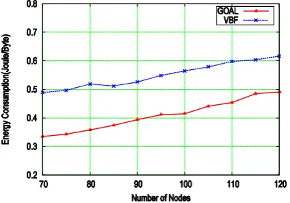
Impacts of node density. In this set of simulations, we set the sensing interval of every node to be 50 s and change the number of nodes in the network from 70 to 120. The size of the DATA packet is fixed to be 300 bytes.
The impact of node density is shown in the next three figures. InFigure 9, we can see that the packet delivery ratio of GOAL is much higher than that of VBF. Again, this is because GOAL reduces more collision than VBF and VBF is a best-effort protocol. Also, we can see that the packet delivery ratio of both GOAL and VBF increases while there are more nodes in the network. One reason as mentioned before is that GOAL largely reduces the MAC collision by performing reservation for DATA packets. The other reason is that it is related to the self-adaptation scheme. Specifically, when the node density is lower, there are fewer qualified next-hops according to the self-adaptation scheme. Particularly, some forwarders do not have a qualified next-hop. In VBF, the DATA packet is dropped in such a case. In GOAL, forwarding failure can be detected by missing the implicit acknowledgement, and therefore a retrans-mission is issued.
FromFigure 10, we can observe that GOAL consumes less energy than VBF for transmitting every unit data from source to sink. The reason is similar to that of Figure 7. In VBF, the collision probability is higher than that in GOAL. Moreover, each collided packet in VBF wastes more energy than that in GOAL because the packet in VBF is much longer. As a result, GOAL saves more energy. Similar to the analysis for Figure 7, if we analyze the energy consumption with the same packet
Figure 7. Energy consumption with varying sensing interval.
delivery ratio, we can see that the energy consumption in GOAL is much less than that in VBF, especially when there are less nodes within the network.
InFigure 11, the delivery delay of GOAL is higher than that of VBF. The reason has been mentioned before: the handshake and implicit acknowledgement in GOAL introduce more delay while VBF is a best-effort protocol which does not care whether the transmission to next-hop is successful. Due to the same reason, the delivery delay of VBF is almost a constant inFigure 11. Addition-ally, we can observe that the delivery delay of GOAL slightly decreases while the node deployment becomes dense. This is because dense deployment improves the probability that the next-hop with a better location can be found. According to the self-adaptation algorithm, a better location implies a shorter backoff time. Therefore, the total delivery delay is reduced.
Impacts of DATA packet size. In this set of simulations, we set the sensing interval and number of nodes as 50 s and 100, respectively. Then, we compare the performance of GOAL and VBF plus broadcast MAC by varying the size of DATA packet from 200 to 400 bytes with step 20.
From Figure 12, as the size of the DATA packet increases, the packet delivery ratio of VBF decreases. This is because a longer DATA packet increases the probability of collisions. However, as shown inFigure 12, the packet delivery ratio of GOAL is almost constant. We believe this is because the reservation scheme in GOAL well prevents the collisions among DATA packets.
FromFigure 13, we can see that both GOAL and VBF consume less energy as the size of the DATA packet becomes larger. This is because the longer DATA packet shortens the time of the idle state. We can still see that GOAL is more energy-efficient than VBF. The reason is the same as mentioned before. The reservation scheme in GOAL can largely reduce the collisions among DATA packets and therefore GOAL wastes less energy.
FromFigure 14, we can observe that GOAL introduces more delivery delay than VBF. The reason is same as the explanation for Figure 11. We can also observe that the delivery delays of both GOAL and VBF become longer while the DATA packet size increases slightly. This is rea-sonable. A longer DATA packet implies longer transmis-sion delay. Since transmistransmis-sion delay is a part of delivery delay, the delivery delay becomes longer.
Figure 9. Packet delivery ratio with varying number of nodes.
Figure 10. Energy consumption with varying number of
nodes.
Figure 11. Delivery delay with varying number of nodes.
Figure 12. Packet delivery ratio with varying DATA packet
5.3. Theoretical model verification
In this section, we perform two sets of simulation to verify the theoretical model of PH~ . In the first set, GOAL is revised as mentioned in Section 4and the relay traffic is disabled. With the results of this set, we can check the model accuracy. After all, it is not a general scenario if nodes do not relay packet. Therefore, we let nodes still forward DATA packets in the other simulation set. By comparing with the results of this set, we can find the gap between our model and the simulation in practical scenario. There are 200 stationary nodes with a transmis-sion range of 100 m uniformly distributed within the net-work of size 500 m· 500 m·500 m, and each node randomly selects a destination node. Then, we vary k
from 0.01 to 0.1 packets s1 with step 0.01 to evaluate
~
PH.
The comparison between simulation results and our theoretical model is shown inFigure 15. FromFigure 15, we can observe that theP~H evaluated by our theoretical
model is always tightly around the simulation results of GOAL without forwarding. This justifies that our theo-retical model matches the simulation results, which also
indicate that our model can well describe the probability of successful handshake.
At the same time, we can see the results of both the theoretical model of GOAL without forwarding are higher than that of GOAL with forwarding. This is rea-sonable. In GOAL with forwarding, nodes also send relay traffic to the channel and therefore the traffic in the chan-nel is apparently much heavier than that in GOAL with-out forwarding. For that reason, there must be more collisions, which reduce the probability of successful handshake.
6. Conclusion
In this paper, GOAL, an efficient geo-routing aware MAC protocol, is proposed for underwater sensor net-works. It is a reservation-based MAC protocol which can smoothly integrate with any existing geo-routing pro-tocols with self-adaptation capability. Self-adaptation based REQ/REP handshake, geographic cyber carrier sensing, and implicit acknowledgement are used in GOAL to improve system performance. Although the end-to-end delivery delay increases because of the hop-by-hop retransmission mechanism in GOAL, it can achieve high end-to-end delivery ratio with low energy consumption. Plentiful simulation results show that GOAL outperforms existing VBF with broadcast MAC in both end-to-end delivery ratio and energy efficiency. Moreover, the simulation results demonstrate that our theoretical model can well describe the probability of a successful handshake.
References
[1] CUI, J., KONG, J., GERLA, M. and ZHOU, S. (2006)
Challenges: building scalable mobile underwater wireless sensor networks for aquatic applications.IEEE Network, Spec. Issue Wireless Sens. Networking20(3): 12–18. [2] HEIDEMANN, J., YE, W., WILLS, J., SYED, A. and LI, Y.
(2006) Research challenges and applications for underwa-ter sensor networking. In Proceedings of IEEE Wireless
Figure 13. Energy consumption with varying DATA packet
size.
Figure 14. Delivery delay with varying DATA packet size.
Figure 15. Comparison between theoretical model of P~H
Communications and Networking Conference (IEEE), 228–235.
[3] PARTAN, J., KUROSE, J. and LEVINE, B.N. (2006) A survey
of practical issues in underwater networks. InProceedings
of ACM WUWNet(ACM), 1–8.
[4] LIU, L., ZHOU, S. and CUI, J. (2008) Prospects and
problems of wireless communication for underwater sensor networks. Wireless Commun. Mobile Comput. 8(8): 977–944.
[5] CHITRE, M., SHAHABUDDEN, S. and STOJANOVIC, M. (2008)
Underwater acoustic communication and networks: recent advances and future challenges. Mar. Technol. Soc. J. 42(1): 103–116.
[6] PERKINS, C.E. and ROYER, E.M. (1999) Ad hoc on-demand
distance vector routing. InProceedings of IEEE Workshop
on Mobile Computing Systems and Applications (IEEE),
90–100.
[7] XIE, P., CUI, J. and LAO, L. (2006) VBF: vector-based
forwarding protocol for underwater sensor networks. In
Proceedings of IFIP Networking(Springer), 228–235. [8] XIE, P., ZHOU, Z., PENG, Z., CUI, J. and SHI, J. (2009)
Void avoidance in three-dimensional mobile underwater sensor networks. InProceedings of International Confer-ence on Wireless Algorithms, Systems, and Applications
(WASA)(Springer), 305–314.
[9] YAN, H., SHI, Z. and CUI, J. (2008) DBR: depth-based
routing for underwater sensor networks. InProceedings of
IFIP Networking(Springer), 72–86.
[10] CHENG, X., SHU, H., LIANG, Q. and DU, H. (2008) Silent
positioning in underwater acoustic sensor networks.IEEE Trans. Veh. Technol.57(3): 1756–1766.
[11] EROL, M., VIERIRA, L.F.M. and GERLA, M. (2007)
AUV-aided localization for underwater sensor networks. In
Proceedings of International Conference on Wireless
Algo-rithms, Systems and Applications (WASA) (Springer),
44–51.
[12] FRAMPTON, K.D. (2006) Acoustic self-localization in a
distributed sensor network.IEEE Sens. J.6(1): 166–172. [13] ZHOU, Z., CUI, J. and ZHOU, S. (2007). Localization for
large scale underwater sensor networks. InProceedings of
IFIP Networking(Springer), 108–119.
[14] ZHOU, Z., CUI, J. and BAGTZOGLOU, A. (2008) Scalable
localization scheme with mobility prediction for
under-water sensor networks. InProceedings of IEEE INFOCOM
(IEEE), 2198–2206.
[15] XIE, P., ZHOU, Z., CUI, J. and SHI, Z. (2007) R-MAC: an
energy-efficient MAC protocol for underwater sensor networks. In Proceedings of International Conference on Wireless Algorithms, Systems and Applications (WASA)
(Springer), 187–198.
[16] PARK, M.K. and RODOPLU, V. (2007) UWAN-MAC: an
energy-efficient MAC protocol for underwater acoustic wireless sensor networks. IEEE J. Oceanic Eng. 32(3): 710–720.
[17] SYED, A., YE, W. and HEIDEMANN, J. (2008) T-Lohi: a new
class of MAC protocols for underwater acoustic sensor networks. In Proceedings of IEEE INFOCOM (IEEE), 231–235.
[18] FULLMER, C.L. and GARCIA-LUNA-ACEVES, J. (1995) Floor
acquisition multiple access (FAMA) for packet-radio networks. In Proceedings of ACM SIGCOMM (ACM), 262–273.
[19] MOLINS, M. and STOJANOVIC, M. (2006) Slotted FAMA: a
MAC protocol for underwater acoustic networks. In
Proceedings of IEEE OCEANS(IEEE), 16–19.
[20] PENG, Z., ZHU, Y., ZHOU, Z. and CUI, J. (2010)
COPE-MAC: a contention-based medium access control protocol with parallel reservation for underwater acoustic networks.
InProceedings of IEEE OCEANS(IEEE), 1–10.
[21] ZHOU, Z., PENG, Z., CUI, J. and SHI, Z. (2009) Analyzing multi-channel MAC protocols for underwater acoustic sensor networks.UCONN CSE Technical Report:
UbiNet-TR08-02.
[22] XIAO, Y., ZHANG, Y., GIBSON, J.H. and XIE, G.G. (2009)
Performance analysis of p-persistent aloha for multi-hop underwater acoustic sensor networks. In Proceedings of
ICESS(IEEE), 305–311.
[23] BIANCHI, G. (2000) Performance analysis of the IEEE
802.11 distributed coordination function. IEEE J. Sel.
Areas Commun.18(3): 535–547.
[24] XIE, P., ZHOU, Z., PENG, Z., YAN, H., HU, T., CUI, J., SHI,
Z.et al. (2009) Aqua-Sim: an NS-2 based simulator for
underwater sensor networks. InProceedings of IEEE/MTS
Oceans(IEEE), 1–7.