Volume No.02, Issue No. 11, November 2014 ISSN (online): 2348 – 7550
ENHANCEMENT OF MICROGRID CONTROL IN
DISTRIBUTION SYSTEM USING FUZZY LOGIC
TECHNIQUE
Gandhi Attada
1, M. Venkateswara Reddy
2 1PG Student,
2Associate Professor
Department of EEE, Vikas Group of Institutions, Nunna, Vijayawada, AP, (India)
ABSTRACT
A micro grid consists of cluster of loads and distributed generators that operate as a single controllable system. As an integrated energy delivery system micro grid can operate in parallel with or isolated from the main power grid. The micro grid concept introduces the reduction of multiple reverse conversions in an individual AC or DC grid and also facilitates connections to variable renewable AC and DC sources and loads to power systems. The interconnection of DGs to the utility/grid through power electronic converters has risen concerned about safe operation and protection of equipment’s. To the customer the micro grid can be designed to meet their
special requirements; such as, enhancement of local reliability, reduction of feeder losses, local voltages support, increased efficiency through use of waste heat, correction of voltage sag or uninterruptible power supply. In the present work the performance of hybrid AC/DC micro grid system is analyzed in the grid tied mode. Here photovoltaic system, wind turbine generator and battery are used for the development of micro grid. Micro grid advantages can be cited as follows: The need for additional suppliers felt due to the rapid growth of load and fossil fuels reduction. Establishing new power generating sources will reduce environmental pollution and global warming. Distributed generation (DG) sources make it easy to combined heat and power (CHP) which increases its efficiency by reducing losses. The resources are suitable for consumers with low capacity.A small hybrid grid has been modeled and simulated using the Simulink in the MATLAB.
Index Terms—Energy Management, Grid Control, Grid Operation, Hybrid Micro Grid, PV System,
Wind Power Generation
I. INTRODUCTION
Recently renewable energy sources are attractive options for providing power in places where a connection to
the utility network is either impossible or unduly expensive. As electric distribution technology steps into next
century, many trends are becoming noticeable that will change the requirements of energy delivery. The ever
increasing energy consumption, soaring cost and exhaustible nature of fossil fuels, and the worsening global
environment have created increased interest in green power generation systems. Renewable sources have gained
worldwide attention due to fast depletion of fossil fuels along with growing energy demand. DC power from
photovoltaic panels (PV) or fuel cells has to be converted into ac using dc/dc boosters and dc/ac inverters in
order to connect to an ac grid. Recently, DC micro grids are resurging due to the development and deployment
of renewable dc power sources and their inherent advantage for dc loads in commercial, industrial and
residential applications. The DC micro grid has been proposed to incorporate various distributed generators and
ac sources have to be converted into dc before connected to a dc grid and dc/ac inverters are required for
Volume No.02, Issue No. 11, November 2014 ISSN (online): 2348 – 7550
conversions, though losses occurring in dc/dc conversions are lesser than those occurring in dc/ac or ac/dc
conversions. Multiple reverse conversions are required in an individual ac or dc grids may add additional loss to
the system operation and will make current home and office appliances more complicated. Thus, a hybrid micro
grid is more beneficial to reduce the processes of multiple reverse conversions in an individual ac or dc micro
grid to facilitate the connection of variable renewable ac and dc sources and loads with the power system in
order to minimize the conversion losses. Since the operational issues of hybrid grid is more complicated than
those of an individual ac and dc micro grids. A micro grid comprises of low voltage distributed systems with
distributed generations, storage devices, loads and interconnecting switches. The operation of micro grids
provide advantages of higher flexibility, better power quality, controllability, efficiency of operation, and
bidirectional power flow between the utility grid and the micro grid in the grid connected mode of operation.
A hybrid ac/dc micro grid is proposed in this paper to reduce processes of multiple reverse conversions in an
individual ac or dc grid and to facilitate the connection of various renewable ac and dc sources and loads to
power system. Since energy management, control, and operation of a hybrid grid are more complicated than
those of an individual ac or dc grid, different operating modes of a hybrid ac/dc grid have been investigated.
II. SYSTEM CONFIGURATION AND MODELING
2.1. Grid Configuration
The ac and dc links are connected together through two transformers and two four-quadrant operating three
phase converters. The ac bus of the hybrid grid is tied to the utility grid. A compact hybrid grid as shown in Fig.
1 is modeled using the Simulink in the MATLAB to simulate system operations and controls. Forty kW PV
arrays are connected to dc bus through
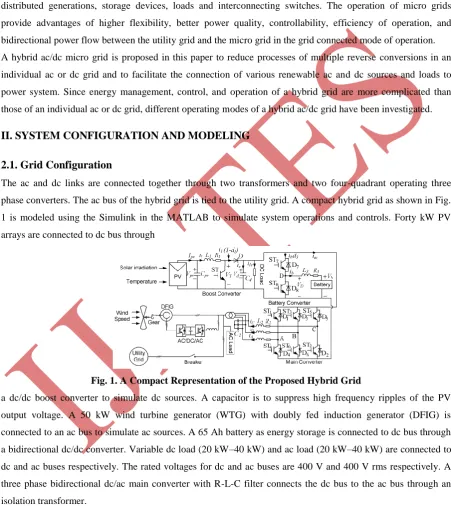
Fig. 1. A Compact Representation of the Proposed Hybrid Grid
a dc/dc boost converter to simulate dc sources. A capacitor is to suppress high frequency ripples of the PV
output voltage. A 50 kW wind turbine generator (WTG) with doubly fed induction generator (DFIG) is
connected to an ac bus to simulate ac sources. A 65 Ah battery as energy storage is connected to dc bus through
a bidirectional dc/dc converter. Variable dc load (20 kW–40 kW) and ac load (20 kW–40 kW) are connected to
dc and ac buses respectively. The rated voltages for dc and ac buses are 400 V and 400 V rms respectively. A
three phase bidirectional dc/ac main converter with R-L-C filter connects the dc bus to the ac bus through an
isolation transformer.
2.2. Grid Operation
The hybrid grid can operate in two modes. In grid-tied mode, the main converter is to provide stable dc bus
voltage and required reactive power and to exchange power between the ac and dc buses. The boost converter
Volume No.02, Issue No. 11, November 2014 ISSN (online): 2348 – 7550
than the dc loads, the converter acts as an inverter and injects power from dc to ac side. When the total power
generation is less than the total load at the dc side, the converter injects power from the ac to dc side. When the
total power generation is greater than the total load in the hybrid grid, it will inject power to the utility grid.
Otherwise, the hybrid grid will receive power from the utility grid. In the grid tied mode, the battery converter is
not very important in system operation because power is balanced by the utility grid. In autonomous
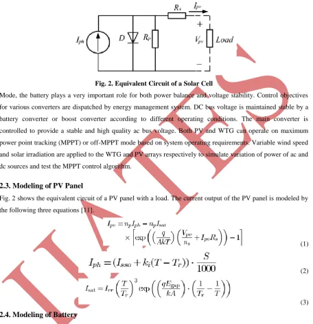
Fig. 2. Equivalent Circuit of a Solar Cell
Mode, the battery plays a very important role for both power balance and voltage stability. Control objectives
for various converters are dispatched by energy management system. DC bus voltage is maintained stable by a
battery converter or boost converter according to different operating conditions. The main converter is
controlled to provide a stable and high quality ac bus voltage. Both PV and WTG can operate on maximum
power point tracking (MPPT) or off-MPPT mode based on system operating requirements. Variable wind speed
and solar irradiation are applied to the WTG and PV arrays respectively to simulate variation of power of ac and
dc sources and test the MPPT control algorithm.
2.3. Modeling of PV Panel
Fig. 2 shows the equivalent circuit of a PV panel with a load. The current output of the PV panel is modeled by
the following three equations [11].
(1)
(2)
(3)
2.4. Modeling of Battery
Two important parameters to represent state of a battery are terminal voltage and state of charge (SOC) as
follows:
(4)
Volume No.02, Issue No. 11, November 2014 ISSN (online): 2348 – 7550
Where is internal resistance of the battery, is the open circuit voltage of the battery, is battery charging
current, K is polarization voltage, Q is battery capacity, A is exponential voltage, and B is exponential capacity.
2.5. Modeling of Wind Turbine Generator
Power output from a WTG is determined by (6)
(6)
Where is air density, A is rotor swept area, is wind speed, and is the power coefficient, which is
the function of tip speed ratio and pitch angle. The mathematical models of a DFIG are essential requirements
for its control system. The voltage equations of an induction motor in a rotating - coordinate are as follows:
(7)
(8)
The dynamic equation of the DFIG
(9)
(10)
where the subscripts d, q, s and T denote d-axis, q-axis, stator, and rotor respectively, L represents the
inductance, is the flux linkage, u and i represent voltage and current respectively, and are the angular
synchronous speed and slip speed respectively, , is the mechanical torque, is the
electromagnetic torque and other parameters of DIFG are listed in Table II. If the synchronous rotating d-
reference is oriented by the stator voltage vector, the q-axis is aligned with the stator voltage vector while the
d-axis is aligned with the stator flux reference frame. Therefore, and . The following equations
can be obtained in the stator voltage oriented reference frame as:
(11)
(12)
Volume No.02, Issue No. 11, November 2014 ISSN (online): 2348 – 7550
III. FUZZY LOGIC CONTROLLERS
The word Fuzzy means vagueness. Fuzziness occurs when the boundary of piece of information is not clear-cut.
In 1965 Lotfi A. Zahed propounded the fuzzy set theory. Fuzzy set theory exhibits immense potential for
effective solving of the uncertainty in the problem. Fuzzy set theory is an excellent mathematical tool to handle
the uncertainty arising due to vagueness. Understanding human speech and recognizing handwritten characters
are some common instances where fuzziness manifests. Fuzzy set theory is an extension of classical set theory
where elements have varying degrees of membership. Fuzzy logic uses the whole interval between 0 and 1 to
describe human reasoning. In FLC the input variables are mapped by sets of membership functions and these are
called as “FUZZY SETS”.
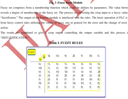
Fig. 3 .Fuzzy Basic Module
Fuzzy set comprises from a membership function which could be defines by parameters. The value between 0 and 1
reveals a degree of membership to the fuzzy set. The process of converting the crisp input to a fuzzy value is called as
“fuzzificaton.” The output of the Fuzzier module is interfaced with the rules. The basic operation of FLC is constructed
from fuzzy control rules utilizing the values of fuzzy sets in general for the error and the change of error and control
action.
The results are combined to give a crisp output controlling the output variable and this process is called as
“DEFUZZIFICATION.”
Table I. FUZZY RULES
Fig. 4 Control Strategy Based On 49 Fuzzy Controls Rule with Combination Of
Volume No.02, Issue No. 11, November 2014 ISSN (online): 2348 – 7550
IV. SIMULATION RESULTS
The operations of the Micro Grid grid under various source and load conditions are simulated to verify the
proposed control algorithms. The parameters of components for the micro grid.
4.1 Grid-Connected Mode
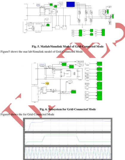
Fig. 5. Matlab/Simulink Model of Grid-Connected Mode
Figure5 shows the mat lab/Simulink model of Grid-Connected Mode
Fig. 6. Subsystem for Grid-Connected Mode
Figure6 shows the for Grid-Connected Mode
Fig. 7. The Terminal Voltage Of The Solar Panel, And PV Output Power Versus Solar Irradiation, AC
Side Voltage And Current Of The Main Converter With Variable Solar Irradiation Level And Constant
Volume No.02, Issue No. 11, November 2014 ISSN (online): 2348 – 7550
Figure7 shows the The terminal voltage of the solar panel, and PV output power versus solar irradiation, AC
side voltage and current of the main converter with variable solar irradiation level and constant dc load.
Fig. 8. DC Bus Voltage Transient Response
Figure8 shows the DC bus voltage transient response.
Fig. 9. AC Side Voltage and Current of the Main Converter with Constant Solar Irradiation Level and
Variable Dc Load
Figure9 shows
AC side voltage and current of the main converter with constant solar irradiation level andvariable dc load
.
Fig. 10. Upper: Output Power Of The DFIG; Lower: AC Side Voltage Versus Current (Voltage Times 1/3
For Comparison)
Figure10 Shows the Upper: output power of the DFIG; Lower: AC side voltage versus current (Voltage times
Volume No.02, Issue No. 11, November 2014 ISSN (online): 2348 – 7550
4.2 Isolated Mode
The control strategies for the normal case and Case 1 are verified. In the normal case, dc bus voltage is
maintained stable by the battery converter and ac bus voltage is provided by the main converter. The reference
of dc-link voltage is set as 400 V. Fig. 16 shows the dynamic responses at the ac side of the main converter
when the ac load increases from 20 kW to 40 kW at 0.3 s with a fixed wind speed 12 m/s. It is shown clearly
that the ac grid injects power to the dc grid before 0.3 s and receives power from the dc grid after 0.3 s.
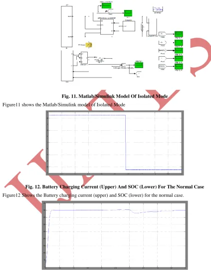
Fig. 11. Matlab/Simulink Model Of Isolated Mode
Figure11 shows the Matlab/Simulink model of Isolated Mode
Fig. 12. Battery Charging Current (Upper) And SOC (Lower) For The Normal Case
Figure12 Shows the Battery charging current (upper) and SOC (lower) for the normal case.
Fig. 13. DC Bus Voltage Transient Response In Isolated Mode
Volume No.02, Issue No. 11, November 2014 ISSN (online): 2348 – 7550
4.3 Grid-Connected Mode With Fuzzy
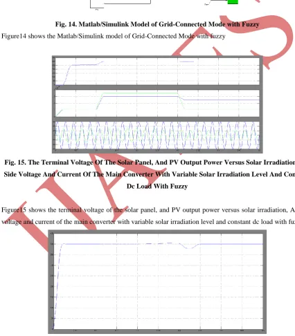
Fig. 14. Matlab/Simulink Model of Grid-Connected Mode with Fuzzy
Figure14 shows the Matlab/Simulink model of Grid-Connected Mode with fuzzy
Fig. 15. The Terminal Voltage Of The Solar Panel, And PV Output Power Versus Solar Irradiation, AC
Side Voltage And Current Of The Main Converter With Variable Solar Irradiation Level And Constant
Dc Load With Fuzzy
Figure15 shows the terminal voltage of the solar panel, and PV output power versus solar irradiation, AC side
voltage and current of the main converter with variable solar irradiation level and constant dc load with fuzzy
Fig. 16 DC Bus Voltage Transient Response With Fuzzy
Volume No.02, Issue No. 11, November 2014 ISSN (online): 2348 – 7550
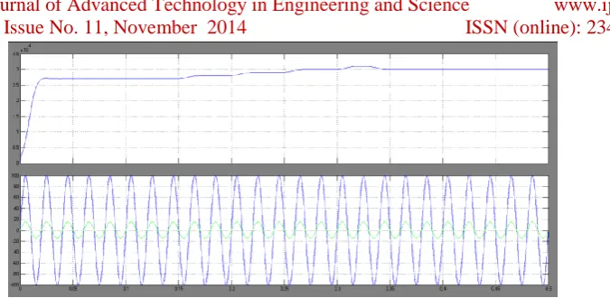
Fig. 17 Upper: Output Power Of The DFIG; Lower: AC Side Voltage Versus Current (Voltage Times 1/3
For Comparison) With Fuzzy
Figure17 shows the Upper: output power of the DFIG; Lower: AC side voltage versus current (Voltage times
1/3 for comparison) with fuzzy.
V.CONCLUSION
A hybrid ac/dc micro grid is proposed and comprehensively studied in this paper. The models and coordination
control schemes are proposed for the all the converters to maintain stable system operation under various load
and resource conditions. The coordinated control strategies are verified by Matlab/Simulink. Various control
methods have been incorporated to harness the maximum power from dc and ac sources and to coordinate the
power exchange between dc and ac grid. Different resource conditions and load capacities are tested to validate
the control methods.The total system efficiency depends on the reduction of conversion losses and the increase
for an extra dc link. It is also difficult for companies to redesign their home and office products without the
embedded ac/dc rectifiers although it is theoretically possible. This Micro Grid system is controlled to give
maximum output power under all operating conditions to meet the load. Either wind or solar system is supported
by the battery to meet the load. Also, simultaneous operation of wind and solar system is supported by battery
for the same load.
REFERENCES
[1] R. H. Lasseter, “MicroGrids,” in Proc. IEEE Power Eng. Soc. Winter Meet., Jan. 2002, vol. 1, pp. 305–308.
[2] Y. Zoka, H. Sasaki, N. Yorino, K. Kawahara, and C. C. Liu, “An inter-action problem of distributed
generators installed in a MicroGrid,” in Proc. IEEE Elect. Utility Deregulation, Restructuring. Power
Technol., Apr. 2004, vol. 2, pp. 795–799.
[3] R. H. Lasseter and P. Paigi, “Microgrid: A conceptual solution,” in Proc. IEEE 35th PESC, Jun. 2004, vol.
6, pp. 4285–4290.
[4] C. K. Sao and P. W. Lehn, “Control and power management of con-verter fed MicroGrids,” IEEE Trans.
Power Syst., vol. 23, no. 3, pp. 1088–1098, Aug. 2008.
[5] T. Logenthiran, D. Srinivasan, and D. Wong, “Multi-agent coordination for DER in MicroGrid,” in Proc.
IEEE Int. Conf. Sustainable Energy Technol., Nov. 2008, pp. 77–82.
[6] M. E. Baran and N. R. Mahajan, “DC distribution for industrial sys-tems: Opportunities and challenges,”
IEEE Trans. Ind. Appl., vol. 39, no. 6, pp. 1596–1601, Nov. 2003.
[7] Y. Ito, Z. Yang, and H. Akagi, “DC micro-grid based distribution power generation system,” in Proc. IEEE
Volume No.02, Issue No. 11, November 2014 ISSN (online): 2348 – 7550
[8] A. Sannino, G. Postiglione, and M. H. J. Bollen, “Feasibility of a DC network for commercial facilities,”
IEEE Trans. Ind. Appl., vol. 39, no. 5, pp. 1409–1507, Sep. 2003.
[9] D. J. Hammerstrom, “AC versus DC distribution systems-did we get it right?,” in Proc. IEEE Power Eng.
Soc. Gen. Meet., Jun. 2007, pp. 1–5.
[10]D. Salomonsson and A. Sannino, “Low-voltage DC distribution system for commercial power systems with
sensitive electronic loads,” IEEE Trans. Power Del., vol. 22, no. 3, pp. 1620–1627, Jul. 2007.
[11]M. E. Ropp and S. Gonzalez, “Development of a MATLAB/simulink model of a single-phase