1009 |
P a g e
REAL TIME PLC BASED CONTROL SYSTEMS
USING WIRELESS SENSOR NETWORKS
1
G.Sathishkumar,
2M.Prabu
1PG Scholar,
2Professor, Nandha Engineering College, Erode-52 (India)
ABSTRACT
A main aim of proposed system is to monitor and control a PLC based system wirelessly for an industry with
wired PLC, it can be achieved using GSM & RF module. In some cases no person is required to do the process
manually. Person can need only to send the reply about the process that is to be carried out and PLC will check
the status of the SMS sent by person and take the action according to it. Status of field is sent to user by PLC
via RF module based on the input status of the sensors that are placed at the field an these simulation of this
project will be carried out by using INTOUCH HMI. To verify the functionality and monitor the temperature
and humidity sensor levels INTOUCH HMI symbol factory tool is used and these system design is implemented
in windows scripts with C language can be generated by using INTOUCH HMI. For implement this project I am
going to use GSM SIM300 module, DVP 10SX PLC, Switches as a sensors, Motors as an output and RS485 to
RS232 converter.
Keywords: GSM, Humidity sensor, INTOUCH HMI, PLC, Pressure sensor, RF module.
1. INTRODUCTION
A programmable logic controller are commonly known as PLC, is a digital, solid state, industrial computer
using for an integrated circuits instead of electromechanical devices to implement their control functions. Also,
it was invented in order to replace their sequential circuits which were mainly used for a machine controls. It is
capable of storing instructions, such as timing, sequencing, arithmetic, counting, data communication and
manipulation, to control machines and processes.
Also, According to NEMA(National Electrical Manufacture’s Association ,USA),the definition of PLC has been
given as Digital electronic devices that can uses a programmable memory and to store instructions and to
implement specific functions such as logic , sequencing, timing, counting, and arithmetic to control machines
and processes.
A PLC programming is done by using a Ladder diagram Language among some several languages. From a
Ladder diagram is specialized an schematic language are commonly used to industrial control logic unit
systems. It called as "ladder" diagram and because it likeness to a ladder with two vertical rails are (supply
power) and as many "rungs" are (horizontal lines) as there are control circuits to represent.
To implement wired PLC with a wireless sensor networks on RF module and some important modules to
increases their efficient communications. Various of important modules are like: Implements GSM module,
System interfaces with RF for Wireless communications, Any location in the field we can know sensors value
1010 |
P a g e
In these Wired PLC are implemented with a wireless sensor networks for efficient transferring data values.
Sensors are controlled and monitored through GSM module corresponding its set value points. For RF module is
to communicate their remote location areas. Depends on that corrected values from set points it can be
functioned. Each process of sensors values can be transferred for dedicated system or a person to knowing their
present situation of field.
II. PROPOSED SYSTEM
PLC based control system with Wireless Sensor Networks. Humidity sensor is to sense how much humidity
present in that place. Depends upon the humidity level solenoid valve will be opened. Also, float sensor is to
sense whether water is reached on a specified limit. Timer based system is also implemented whenever if
possible.
Through RF module can monitor and control their complete process automation. Adding of GSM module can
knows their status of working operation in these system.
III. BLOCK DIAGRAM
Fig.1 Block Diagram
The above block diagram Fig.1 represents the automatic control mechanism. Here each of the functional unit is
represented in a block. Basic function of the whole of the system is to control by an RF module. Main control
unit of the circuit is the PLC controller whose description is given before.
Delta10sx PLC controller works on a voltage of 24V DC so it is fed from SMPS power supply unit through a
plug. The humidity sensor sense the humidity in soil and gives analog voltage input to controller A/D port,
similarly the “float sensor” also sense the water level reached or not and passes the voltage signal to controller.
The A/D converter are converts the analog signals into an digital signals which is compared by an values to
controller. Whenever the humidity level is below then the solenoid valve is switched ON and kept running till
1011 |
P a g e
3.1 Components & Description
3.1.1 RS485 to RS232 Converter
It is a converter that converts the rs232 communication port to rs485 communication port. It needs the separate
power supply to convert the data. At rs485 side one connection is for power supply, two connections for an
ground, and remaining two are for rs485A and rs485B.
3.1.2 GSM Module
Fig.2 GSM Circuit Diagram
This GSM Modem can accept any GSM network operator SIM card and act just like a mobile phone with its
own unique phone number in it. Advantage of using this modem will be that you can use its RS232 port to
communicate and develop embedded applications. Most of applications like data transfer, SMS Control, remote
logging and control can be developed easily.
The modem can either be connected to PC serial port directly or to any microcontroller or PLC. It can be used to
send and receive SMS . They can be a also used in GPRS mode to connect to internet and do many applications
for data control and logging. In GPRS mode you can also connect to any remote FTP server and upload files for
data logging.
3.1.3 Delta PLC DVP10SX
The name itself suggests the type of PLC and I/O it provides like DVP is a series name, 10 stands for (6+4) 6
inputs and 4 outputs, SX series as shown in fig 4. The delta PLC is cheaper than other brands of the PLC and
easy to configure with any application of industry as well.
3.2 Sensors
3.2.1 Pressure Sensor
Pressure sensors have been in demand since the advent of the steam age. In such sensors are used daily to
monitor the pressure of fluids in engines, pipes, hydraulics. Some specialized sensors are also used to determine
the pressure of gases or solids. A typical pressure sensor is about a cubic inch in sizes, some may be a hundred
1012 |
P a g e
3.2.2. Float Sensor
Fig.3 Float sensor working Diagram
Here the principle behind these mechanical, cable, magnetic and other float level sensors are involves the
opening or closing of an mechanical switches, and also either by direct contact with their switches, or magnetic
operation of a reeds. With an magnetically actuated float level sensors, it switching occurs when a permanent
magnet is sealed inside a level float rises or falls to the actuation level on it.
With a mechanically actuated float level, switching take places as a result of the movement on float against a
miniature of (micro) switches. For an both mechanical and magnetic float sensor, temperature, chemical
compatibility, specific gravity (density), and viscosity affect the selection of the stem and the float.
3.2.3 Solenoid Valve
Solenoid valve is an electromechanically functioned valve for a controlling process. These valves are controlled
by it electric current
and
through a solenoid: in a such case of two-port valve has flow is switched either on oroff; and also in the case of a three-port valve, here outflow is switched in between depends on two outlet ports.
Multiple of solenoid valves can also to be placed together on manifold.
And solenoid valves are the most often used control elements in their fluidics. From tasks are to be shut off,
dose, release, distribute or mix fluids. These are found in several application areas. Solenoids offer fast and safe
switching, long service life, high reliability, good medium compatibility of materials used, low controlling
power and compact designs.
Besides the plunger-type actuator which is used most frequently, pivoted-armature actuators and rocker
actuators are also used.
IV. SIMULATION & RESULT
Hence the programming sides first have to configure the PLC in a communication mode for communication
purposes and it is usual part for all types of PLC for communication. And that next have to SET as memory bit
for every an AT commands to communicate with their GSM module. After that enter the code of hex for all that
1013 |
P a g e
Similarly should load their program in corresponding PLC and connect their RS485 to RS232 converter at
RS485 terminal is to be provided in these PLC and at other end of the cable should connected to RS232 cable
and whose another end of cable will be connected to a GSM module.
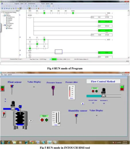
Fig 4 RUN mode of Program
Fig 5 RUN mode in INTOUCH HMI tool
Fig 4 & Fig 5 shows their RUN mode in application mode & simulation of Run mode in INTOUCH HMI tool
software.
4.1 Application
1014 |
P a g e
4.2 Future Enhancement
In this future it can extend their scope of PLC for wireless application by interfacing ZIGBEE module with PLC
and it can get their same result as ZIGBEE modules interfaced with controller. By adding additional parameters
of some sensors it improves their performance of these systems.
V. CONCLUSION
From these simulations shown above it can conclude that interfacing of GSM and RF module with PLC is done
successfully and these can use it at any PLC based industry for wirelessly controlling and monitoring of industry
process and also they can use it for agriculture processes are based on PLC.
REFERENCES
[1] Piotr kransiki, Bartosz Pekoslawksi, and Andrej Napieralski, “IEEE 802.15.4 Wireless Network
Application in Real Time PLC Based Control Systems”, International Journal of Microelectronics Nd
Computer science,VOL4,NO 4,2013.
[2] A.M Gaur*, Rajesh Kumar , Amod Kumar and Dinesh Singh Rana, “PLC Based Automatic Control of
Rheometer”, International Journal of Control and Automation Vol. 3 No. 4, December, 2010.
[3] Aka yleh Ali, Mohammed Al_Soud, Essam Abdallah, Salah Addallah, “Water Pumping System with
PLC and Frequency Control”, JJMIE Volume 3, Number 3,September 2009.
[4] Alphy John, I.Bildass Santhosam,” Home Energy Management System Based On Zigbee”,
International Journal of Inventive Engineering and Sciences (IJIES) ISSN: 2319–9598, Volume-2,
Issue-4, March 2014.
[5] Coia Ferrater-Simón, Lluís Molas-Balada, Oriol Gomis-Bellmunt, Member, IEEE, Noelia
Lorenzo-Martínez, Oriol Bayó-Puxan, and Roberto Villafafila-Robles, Student Member, IEEE,” A Remote
Laboratory Platform for Electrical Drive Control Using Programmable Logic Controllers” IEEE
Transactions On Education, Vol. 52, No. 3, August 2009.
[6] Francesco Basile, Senior Member, IEEE, Pasquale Chiacchio, Senior Member, IEEE, and Diego
Gerbasio,” On the Implementation of Industrial Automation Systems Based on PLC,” IEEE
Transactions On Automation Science And Engineering, Vol. 10, No. 4, October 2013.
[7] G.Sathishkumar, M.Prabu, “PLC and SCADA Based Automation in Testing of Water and Drinking
Water Supplying Unit” International Journal of Science and Research (IJSR) ISSN (Online):