IOP Conference Series: Materials Science and Engineering
PAPER • OPEN ACCESS
The application of interference fits for overcoming
limitations in clamping methodologies for
cryo-cooling first crystal configurations in x-ray
monochromators
To cite this article: J Stimson et al 2017 IOP Conf. Ser.: Mater. Sci. Eng. 278 012055
View the article online for updates and enhancements.
Related content
A Numerical Analysis on a Compact Heat Exchanger in Aluminum Foam
B Buonomo, D Ercole, O Manca et al.
-A deformable heat exchanger separated by a helicoid
F Riordan
-Nuclear Power: Heat exchanger for fast reactors
1234567890
CEC 2017 IOP Publishing
IOP Conf. Series: Materials Science and Engineering 278 (2017) 012055 doi:10.1088/1757-899X/278/1/012055
The application of interference fits for overcoming limitations
in clamping methodologies for cryo-cooling first crystal
configurations in x-ray monochromators
J Stimson1, P Docker2, M Ward1, J Kay2, L Chapon2 and S Diaz-Moreno2
1 Birmingham City University, Curzon Street, Birmingham, United Kingdom, B4 7XG 2 Diamond House, Harwell Science and Innovation Campus, Fermi Ave, Didcot OX11
0DE
Abstract. The work detailed here describes how a novel approach has been applied to overcome the challenging task of cryo-cooling the first monochromator crystals of many of the world’s synchrotrons’ more challenging beam lines. The beam line configuration investigated in this work requires the crystal to diffract 15 Watts of 4-34 keV X-ray wavelength and dissipate the additional 485 watts of redundant X-ray power without significant deformation of the crystal surface. In this case the beam foot print is 25 mm by 25 mm on a crystal surface measuring 38 mm by 25 mm and maintain a radius of curvature of more than 50 km. Currently the crystal is clamped between two copper heat exchangers which have LN2 flowing through them. There are two conditions that must be met simultaneously in this scenario: the crystal needs to be clamped strongly enough to prevent the thermal deformation developing whilst being loose enough not to mechanically deform the diffracting surface. An additional source of error also occurs as the configuration is assembled by hand, leading to human error in the assembly procedure. This new approach explores making the first crystal cylindrical with a sleeve heat exchanger. By manufacturing the copper sleeve to be slightly larger than the silicon crystal at room temperature the sleeve can be slid over the silicon and when cooled will form an interference fit. This has the additional advantage that the crystal and its heat exchanger become a single entity and will always perform the same way each time it is used, eliminating error due to assembly. Various fits have been explored to investigate the associated crystal surface deformations under such a regime
1. Introduction
2 1234567890
CEC 2017 IOP Publishing
IOP Conf. Series: Materials Science and Engineering 278 (2017) 012055 doi:10.1088/1757-899X/278/1/012055
device causes the electron to remain close to the emitted photons, resulting in the emitted light falling into the X-ray range. (1–3)
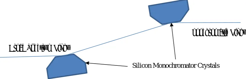
This raw light is produced as a broad spectrum, from which one wavelength is selected via Bragg diffraction (4) using a series of single crystal silicon monochromator as shown in figure 1. These silicon crystals diffract the selected X-ray wavelength, dependent on the angle of incidence, and absorb the rest of the spectrum. As these synchrotron facilities are upgraded these first crystals are expected to absorb more power to the point that the current cooling methods have reached a plateau where any further increase to beam power results in significant thermal deformation of the diffracting surface (5).
Figure 1. The path of a beam through the monochromator series.
There are two main approaches to cooling the silicon crystals: they are most often cooled indirectly, through contact with a heat exchange unit with a through flow of liquid nitrogen; in some cases they are cooled directly, by flowing liquid nitrogen through the body of the crystal itself. Indirect cooling has become the industry standard mainly because heat exchangers are easily constructed, whereas direct cooling requires delicate seals which are only functional for a finite number of cycles before they must be replaced, resulting in far greater costs (6). Until now indirectly cooling the monochromators has been sufficient, but with rising power levels many facilities are looking for new solutions to handle higher heat loads.
The efficiency of indirectly cooling the crystals is dominated by the force applied (7), so that the best way to improve indirect cooling efficiency is to increase the force applied. This is due to only a small number of asperities on the two surfaces actually coming into contact; increasing the force applied deforms these asperities, allowing more to contact. Thus, in order to cool the crystal in the most efficient fashion we need to apply greater and greater forces. However, these forces can in themselves mechanically deform the diffracting surface, potentially causing a greater issue than the heat itself. This means that increasing the clamping forces reduces thermal deformation, but increases mechanical deformation. This suggests that there would be a point where the mechanical deformation overcame the thermal as the dominant deformation, although a literature search found no documentation on such an occurrence.
The final factor to consider for such a cooling system is the distribution of the stress field. If the stress field is applied in a non-uniform pattern, it would cause a non-uniform deformation of the monochromator crystal before any thermal load was even applied (8). As such it is vital that the stress field is uniform.
A current limitation of the system is that the physical assembly of the monochromator imparts multiple stress vectors of varying magnitude and direction, through tightening bolts, attaching the liquid nitrogen manifold and differing thermal expansion coefficients of different materials. Any new system should be adapted to avoid these shortfalls, by not tightening the assembly with bolts, applying the liquid nitrogen manifold parallel to the diffracting surface and minimizing or utilizing the varying thermal expansion characteristics of the materials used.
Broad Spectrum Light
Monochromatic Light
1234567890
CEC 2017 IOP Publishing
IOP Conf. Series: Materials Science and Engineering 278 (2017) 012055 doi:10.1088/1757-899X/278/1/012055
2. Method
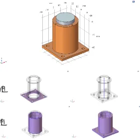
In order to produce a high intensity, uniform stress field an interference fit was modelled using the COMSOL MultiPhysics Finite Element Modelling software, with the copper heat exchanger designed as a sleeve around the silicon crystal as shown in figure 2.
Figure 2. An interference fit monochromator design with copper sleeve as the hub component and single crystal silicon shaft as the shaft component.
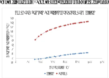
An interference fit is created when two objects attempt to occupy the same space, interfering with each other. In most cases it is achieved by heating the hub component, expanding it thermally, and then slotting it over the shaft component. As the hub cools, it shrinks, bringing it into contact with the shaft component (9). However, with two dissimilar materials such as copper and silicon, it becomes more complex. First, copper has a thermal expansion coefficient an order of magnitude greater than that of silicon. Secondly, silicon experiences a negative thermal expansion coefficient beneath 120 K, causing it to expand when the silicon is cooled. These thermal expansion coefficients are shown in figure 3 (10– 12).
Figure 3. Thermal expansion coefficients of Silicon and Copper. -2
0 2 4 6 8 10 12 14 16 18
0 50 100 150 200 250 300 350
Ex
p
an
si
o
n
Co
eff
ic
ie
n
t
(10
-6/K)
Temperatiure (K)
Thermal Expansion Coefficients of Copper and Silicon
4 1234567890
CEC 2017 IOP Publishing
IOP Conf. Series: Materials Science and Engineering 278 (2017) 012055 doi:10.1088/1757-899X/278/1/012055
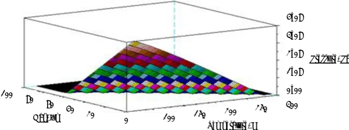
Due to the extreme variation between the two coefficients, it is possible to leave a gap at room temperature and still achieve a high pressure interference fit after cooling. In order to identify whether there should be a gap, and if so what size, the equation below (9) was used to model the pressure achieved during cooling at bare contact and at a range of room temperature gap values analytically in SciLab, the output of which is shown in figure 4.
𝑃 = 𝑑𝑠𝑜− 𝑑ℎ𝑜+ Δ𝑇(𝛼𝑠− 𝛼ℎ)𝑑ℎ𝑖
𝑑ℎ𝑖
𝐸ℎ ∗ (
𝑑ℎ𝑜2 + 𝑑ℎ𝑖2 𝑑ℎ𝑜2 − 𝑑
ℎ𝑖
2 + 𝜈ℎ) +𝑑𝐸𝑠𝑜
𝑠 ∗ (
𝑑𝑠𝑜2 + 𝑑𝑠𝑖2
𝑑𝑠𝑜2 − 𝑑𝑠𝑖2
− 𝜈𝑠)
(1) Where:
𝑑ℎ𝑖 is the inner diameter of the hub
𝑑ℎ𝑜 is the outer diameter of the hub
𝑑𝑠𝑖 is the inner diameter of the shaft
𝑑𝑠𝑜 is the outer diameter of the shaft
𝐸ℎ is the Young’s modulus of the hub
𝐸𝑠 is the Young’s modulus of the shaft
𝜈ℎ is the Poisson’s ratio of the hub
𝜈𝑠 is the Poisson’s ratio of the shaft
Δ𝑇 is the temperature difference between assembly and operation
𝛼𝑠 is the thermal expansion coefficient of the shaft
𝛼ℎ is the thermal expansion coefficient of the hub
Figure 4. Pressure as a function of temperature and gap at room temperature.
To determine the pressure we wanted to induce in the system we considered three factors. First we compared the ultimate compressive stresses of silicon and copper in literature, coming to values of 700 MPa (11) and 358 MPa (12) respectively. As the value for silicon is nearly twice that of copper, we can be confident that the copper sleeve will plastically deform around the silicon, rather than crushing it.
Next, in order to maintain a flat diffracting surface we needed to ensure that the force of linear expansion produced by the silicon’s expansion, as shown in equation 2, would be greater than the friction caused by the copper clamping on the silicon, as shown in equation 1 above. (13). Equation 2 allows us to calculate the force generated from the thermal deformation of either material should they be constrained and unable to move. By solving equation 2 simultaneously for the silicon and copper components we are able to find the axial clamping force. If the axial clamping force exceeds the linear expansion force, the interference face of the silicon would be restrained while the core is relatively free, resulting in a bulge in the center of the diffracting face; whereas if the expansion force were to be greater
100
80 60
40 20
0
Gap, μm 100 150 200
1234567890
CEC 2017 IOP Publishing
IOP Conf. Series: Materials Science and Engineering 278 (2017) 012055 doi:10.1088/1757-899X/278/1/012055
the silicon interference face would slip against the copper. We can tune this axial clamping force by leaving a gap between the two materials at room temperature, as shown in Figure 4 above.
𝐹 = 𝛼𝑌𝐴Δ𝑇
(2) Where:
𝐹 is the force produced
𝛼 is the coefficient of thermal expansion
𝑌 is the Young’s Modulus of Elasticity 𝛥𝑇 is the change in temperature
Finally we had to consider the performance of the current system; to produce a comparable thermal transport we would have to at least match the clamping pressure of the existing system, which is set at 190 N.
3. Results
Solving equations 1 and 2 together we came to an optimal room temperature gap value of 60 μm in order to give us the highest possible pressure without mechanically constraining the interference face of the silicon. We then built another FMA model in COMSOL using this gap, the boundary conditions of which are shown in Figure 5. By assigning the bottom-most surface as unable to move in the z-direction and a central axis as unable to move in the x- or y- directions, we produce a stable and well-constrained model that is subject to thermal expansion. We then held the inner surfaces of the hollow copper sleeve constant at 80 K to simulate the flow of liquid nitrogen, and all outer surfaces of the copper as radiating to a temperature of 80 K to simulate a heat shield.
Figure 5. Copper and silicon interference fit model with a 60 μm gap at room temperature. a) Mechanical boundary conditions, left to right: Shaded surface subject to prescribed displacement
(z = 0); Bold line subject to prescribed displacement (x & y = 0).
b) Thermal boundary conditions, left to right: Shaded surfaces subject to fixed temperature (80 K); Shaded surfaces subject to diffuse surface (to 88 K).
(a)
6 1234567890
CEC 2017 IOP Publishing
IOP Conf. Series: Materials Science and Engineering 278 (2017) 012055 doi:10.1088/1757-899X/278/1/012055
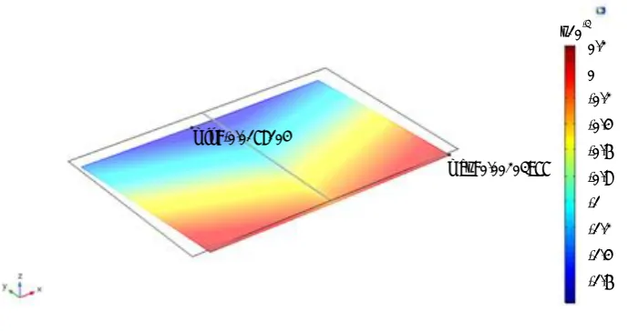
After the model reached a steady state, effectively cooling from 300 K to 80 K, the resulting surface profile is shown in Figure 6. The entire surface is pushed up 5.2 μm, and the edge is raised a further 0.1 μm. The surface is also very uniformly deformed, due to the circular stress field acting on a circular crystal.
Figure 6. Deformation of diffracting surface after applied mechanical pressure.
We compared this surface deformation of our new design to one generated by a model of the existent system, as shown in Figure 7.
Figure 7. Copper and silicon standard assembly model.
a) Mechanical boundary conditions, left to right: Shaded surface subject to fixed constraint; Shaded surface subject to prescribed displacement (z = 0); Shaded volume pretensioned (190 N).
Surface: Displacement field, Z component (mm) Max/Min Surface: Total displacement (mm)
min: 0.00520101
max: 0.00533413
x10-3
5.2
(a)
1234567890
CEC 2017 IOP Publishing
IOP Conf. Series: Materials Science and Engineering 278 (2017) 012055 doi:10.1088/1757-899X/278/1/012055
b) Thermal boundary conditions, left to right: Shaded surface subject to fixed temperature (80 K); Shaded surface subject to diffuse surface (to 88 K).
Figure 7 shows the first crystal monochromator assembly currently used at the I20 beamline at Diamond Light Source in Oxford, with a copper base-plate and heat exchange attached to two silicon crystals by way of two stainless steel bolts. Matching boundary conditions were used where possible, with the bottom surface secured in the z-direction and the fastening bolt for the assembly treated as a true fixed domain. The bolts in this model were pre-tensioned with a 190 N force to match standard operating procedure. Again, the inside of the heat exchangers were fixed at 80 K to simulate the flow of liquid nitrogen, and all outer surfaces were treated as radiating to 80 K to simulate a heat shield.
The surface profile of one of the silicon crystals is shown in Figure 8. The surface is bent in a “V” shape by the differing expansion coefficients of the various materials, with the center being pulled down by 17.8 μm and the outer corners being raised by 2 μm. The deformation varies significantly along the x-axis, due to the differing materials exerting different stress profiles on the crystal.
Figure 8. Deformation of diffracting surface after applied mechanical pressure.
4. Discussion
The results show that an interference fit is capable of applying enough force to parallel that used in the existing system without applying such force that the diffracting surface would be significantly mechanically deformed. This means an interference cooled crystal will be capable of giving us a reduced surface deformation compared to a standard rectangular crystal and heat exchange assembly, due to the far more uniform stress field and higher force between the crystal and the heat exchange. This would allow us to use higher beam powers without deforming the diffracting surface such that the beam is lost.
In addition, by clamping the crystal using an interference fit we would not be introducing strains and rotations to the assembly as are conventionally incurred by manually assembling the system using bolts. It will also give us a far more precise control over the clamping pressure than achieving it by turning nuts. The use of fewer materials, and the application of the differing material properties to create the clamping, results in a more uniform temperature profile.
5. Further Work
In light of the models presented in this work, we are now in the process of manufacturing heat exchangers to fit cylindrical silicon crystals. A Fizeau interferometer will be used to measure the surface deformation imparted by interference fits of varying magnitudes.
Surface: Displacement field, Z component (mm) Max/Min Surface: Total displacement (mm)
max: 0.00203977 min: -0.0178104
x10-3 0.2 0 -0.2
-0.4 -0.6
-0.8 -1
-1.2
8 1234567890
CEC 2017 IOP Publishing
IOP Conf. Series: Materials Science and Engineering 278 (2017) 012055 doi:10.1088/1757-899X/278/1/012055
In addition, we will be exploring the application of the interference fit to produce a gas-tight seal by decreasing the gap, possibly even to the extent of interference fitting above room temperature. The pressures involved should be able to produce a gas-tight seal without significantly deforming the diffracting surface of the crystal. To test this theory, the heat exchange sleeves will be tested to see if they are able to hold a gas-tight seal.
6. References
1. McMillan EM. The Synchrotron – A Proposed High Energy Particle Accelerator. Phys Rev. 1945;68(143):1–4.
2. Wilson EJN. Fifty years of synchrotrons. In: 5th European Particle Accelerator Conference. Spain; 1996. p. 135–9.
3. Sham TK, Rivers ML. A Brief Overview of Synchrotron Radiation. Rev Mineral Geochemistry. 2002;49(1):117–47.
4. Bragg WH, Bragg WL. The Reflexion of X-rays by Crystals. In: Proceedings of the Royal Society of London. The Royal Society; 1913. p. 428–38.
5. Zhang L, Sánchez Del Río M, Monaco G, Detlefs C, Roth T, Chumakov AI, et al. Thermal deformation of cryogenically cooled silicon crystals under intense X-ray beams: Measurement and finite-element predictions of the surface shape. J Synchrotron Radiat. 2013;20(4):567–80. 6. Marion P, Zhang L, Goirand L. Cryogenic cooling of monochromator crystals: Indirect or
direct cooling? In: Proceeding MEDSI 2006. Grenoble; 2006.
7. Salerno LJ, Kittel P. Thermal contact conductance. J Mater Process Technol. 2003;135(2– 3):204–10.
8. Malvern LE. Introduction to the mechanics of a continuous medium. Prentice-Hall; 1969. 713 p.
9. Bower AF. Applied Mechanics of Solids. 1st ed. 2011. 820 p.
10. Shah JS, Straumanis ME. Thermal expansion behavior of silicon at low temperatures. Solid State Commun. 1972 Jan;10(1):159–62.
11. Petersen KE. Silicon as a Mechanical Material. Proc IEEE. 1982;70(5):420–57.
12. National Institute of Standards and Technology (NIST). Properties of Copper and Copper Alloys at Cryogenic Temperatures. 1992;Monograph:270. Available from:
http://nvlpubs.nist.gov/nistpubs/Legacy/MONO/nistmonograph177.pdf