Sherif. World Journal of Engineering Research and Technology
AUTOMATIC CONTROL OF THE ELECTRICAL AUTOPILOT OF
THE AIRCRAFT
Ahmed Soliman M. Sherif*
Researcher, Novosibirsk State Technical University, Department of Aircraft and Helicopter Construction, Russian Federation.
Article Received on 04/04/2017 Article Revised on 26/04/2017 Article Accepted on 17/05/2017
ABSTRACT
The Electrical Autopilot of the Aircraft works as follows: First, set the course, which should fly the plane. After this, the course gyroscope, whose axis is horizontal, is untwisted. If the aircraft deviates from the course as a result of external influence, the gyroscope retains its position in space and the sliders of the main potentiometer occupy a new position. Since the main potentiometer is connected to the potentiometer of feedback via the bridge circuit, in this circuit a voltage appears which is a misunderstanding. This signal is amplified by the MA and transmitted to the EA, then to the motor. The electric motor drives the steering wheel, which rotates in the desired direction. The sliders of the feedback potentiometer move with the rudder to a position where the mismatch becomes zero (the sliders of the feedback potentiometer occupy the same position as the sliders of the main potentiometer). The rudder stops rotating, and the aircraft, under the influence of the rudder, turns to the desired course. When turning the plane, the main gyroscope moves the sliders of the main potentiometer in the opposite direction. Again, a mismatch occurs, but the signal to the rudder in this case is reversed and the electric motor rotates the rudder in the opposite direction to the neutral position. When the plane returns to the course, the rudder will take a neutral position and the aircraft will continue to fly at the rate.
World Journal of Engineering Research and Technology
WJERT
www.wjert.org
SJIF Impact Factor: 4.326*Corresponding Author Ahmed Soliman M. Sherif
Researcher, Novosibirsk
State Technical University,
Department of Aircraft and
Helicopter Construction,
KEYWORDS: Aircraft Autopilot, Hodograph Mikhailova, Gyroscope, Electromotive Amplifier, Magnetic Amplifier, Electromotive Amplifier, potentiometer, Electric Motor, Rudder,Automatic System Regulation and Management.
INTRODUCTION
Abbreviations of research terminology
- The setting influence on the system (the voltage in bridge connection of the potentiometer gyroscope and potentiometer feedback, which is located at the Steering and connected with it mechanically;
G - Gyroscope by means of which the course of the aircraft is set;
MA - Magnetic Amplifier, amplifies and transmits a signal to electromotive amplifier; Δ - Mismatch of the main potentiometer (gyro) and rudder feedback potentiometer; EA - Electromotive Amplifier, receives a signal from MA, converts it into an electric and amplifies it to a working one for the rudder motor;
EM - Electrical Motor, through the relay receives a signal from EA and turns steering wheel in the right direction;
SW - Steering Wheel (Rudder), deviates along with the potentiometer slider feedback; A - Aircraft, takes a course in accordance with a given gyrocompass course and rudder position.
Initial data of the Research
№ Automatic Regulation Elements Initial data 1 Course Sensor - Gyroscope К1: 0.5
Т1,с: 0.01 2 Magnetic Amplifier К2: 2 3 Electromotive Amplifier К3: 3 4 Electric Motor К4: 1.5
1. The concept of the Automatic System Regulation and Management (ASRandM)
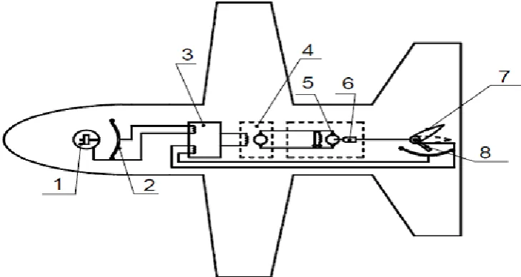
Fig 1.1: Schematic diagram of the Electrical Autopilot of the Aircraft. 1 - The gyroscope; 2 - potentiometer; 3 - magnetic amplifier; 4 - electromotive amplifier; 5 - The electric motor; 6 - reducer; 7 - steering wheel; 8 - feedback potentiometer
2. Composing a detailed block diagram of (ASRandM) and describing its Principle
Fig 2.1: Functional diagram (block diagram) of the Aircraft control system by Autopilot at the rate.
3. Differential Equations and Transfer Functions Elements of (ASRand M)
In accordance with the task of characterizing the law, the changes in the output coordinate from the input elements (links) of the (ASR and M) are subdivided into:
- links 1, 4, 6 - Aperiodic;
- links 2, 3, 5 - proportional (Amplifying).
The differential equations of motion of the elements (ASR and M) in the usual and operator
link 1 (G)
- usual form:
- operator form:
Where,
link 2 (MA)
- usual form:
- operator form:
link 3 (EA)
- usual form:
- operator form:
MA G
link 4 (EM)
- usual form:
- operator form:
link 5 (SW)
- usual form:
- operator form:
link 6 (A)
- usual form:
- operator form:
EM
SW
- The transfer functions of the links (ASRandM): link 1 (G)
link 2 (МA)
link 3 (EA)
link 4 (EM)
link 5 (SW)
link 6 (A)
4. Structural diagram of (ASRandM) with indication of transmission signals:
Fig.4.1. Block diagram of the Aircraft control system by Autopilot at the rate:
5. Formulate differential equations and transfer functions of open-loop and closed-loop (ASRandM) by a control signal.
“An open system is a system in which the closing relationship between the coordinates is torn”.
Let us write for the open system, the differential equations of motion of links of an open circuit in the operator form.
“We exclude all the coordinate variables sequentially, except and get the differential equation of motion of the open circuit”.
To obtain the differential equation of motion of a closed system:
Then for a closed system the differential equation of motion takes the form:
6. Defining the unknown transmission coefficient from the stability condition (ASRandM)
by the Hurwitz criterion.
The characteristic equation has the form:
In this equation
We compose the Hurwitz determinant:
For the characteristic equation of the third order in accordance with the recommendations of,[1] we have the following stability conditions:
In our case
From the third condition we have K5> (-0.1107). From the fourth condition we have Ks <1094.
Thus, the value of the transfer coefficient K5 for stable operation of the control system lies in the range [-0.1107 <K5 <1094],
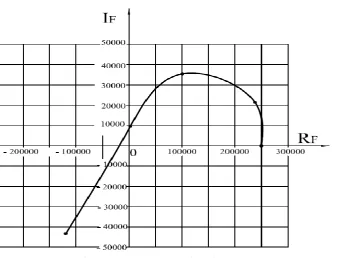
7. We will construct the Hodograf Mikhailova by recommendations.[2]
Hodograph Mikhailova is used to study the stability of a system with the help of a complex variable function. To investigate this complex characteristic F(j), which is obtained from the characteristic polynomial P replaced by j.
The characteristic equation has the form:
The characteristic polynomial of this equation is:
Characteristic complex:
We represent the characteristic complex in the form:
Calculation the values of the real and imaginary parts of the characteristic complex at specific values of the frequency (Table 1).
Table 1:
0 10 35 45 55
250277.8 238047 100460 2620 - 119679 0 21375 35437 9562 - 43312
CONCLUSIONS
I. The principle of operation of the system under consideration is as follows. Gyro is a measuring or sensitive element of the course automatic. The gyro axis is rigidly connected to the slider potentiometer 2, and the body of the gyro is with the airframe. II. When the aircraft deviates from the predetermined heading, the airplane body and the
potentiometer deviate from the potentiometer 2, which remains unchanged in the space of the slider. As a result, the potentiometer removes the electric signal from the slider, the magnitude and sign of which are determined by the deviation of the aircraft from the target course.
III.This weakness of the electrical signal enters the magnetic, and then the electric machine amplifier. Where it is amplified to a value sufficient to control the operation of a rather powerful electric motor, which by means of a reducer turns the rudder of the aircraft in the required directions and simultaneously the slider feedback potentiometer.
IV.With the aim of constructing the Hodograph Mikhailova curve, we calculate the values of the real and imaginary parts at specific frequencies.
REFERENCES
1. Krinetsky E.E., Fundamentals of Aviation Automation - Moscow: Mechanical
engineering, 1969.
2. Vostrikov A.S., Frantsuzova G.A. The theory of automatic control. Textbook. Allowance. -
Novosibirsk. Publishing house of NSTU, 2006.
3. Jiratkova L.A., Basics of Automatic Control. - Novosibirsk Publishing house of NSTU,
2009.