Photoelaticity and Its Application to Structural Analysis. A Review Based
on Professor Vlatko Brčić Achievements
K. R. (Stevanović) Hedrih1,2,*, S. Paunović1,3
1 Mathematical Institute of the Serbian Academy of Sciences and Arts, Belgrade, Serbia
e-mail: khedrih@sbb.rs
2 Faculty of Mechanical Engineering, University of Niš, Niš, Serbia
3 Faculty of Architecture and Civil Engineering, University of Niš, Niš, Serbia
e-mail: stepa.paunovic@gmail.com *corresponding author
Abstract
Professor Vlatko Brčić was a very prominent scientist-theoretician, researcher and engineer, and he had a profound scientific influence on the development of civil engineering and stress analysis of civil engineering structures in the Western Balkans. This paper presents a brief overview of the scientific results and engineering activity of prof. Brčić, as well as a report on his research regarding the improvement and application of the photoelasticity method in stress state analysis of various engineering structures, while the results and influence of his work are discussed in more detail.
Keywords: photoelasticity; isochromatics; isoclinics; Vlatko Brčić; stress state; gravity dams
1. Introduction
Prof. Dr. Eng. Sci. and Dipl. Math. Vlatko Brčić (September 16, 1919, Varaždin, Croatia, Yugoslavia - August 22, 2000, Belgrade, Serbia) was one of those great people whose life and work do not cease to inspire young and additionally encourage more experienced researchers and engineers. Vlatko Brčić received his graduate degree in Theoretical Mathematics and Physics from the Faculty of Philosophy, at the University in Zagreb, Croatia (Republic of Yugoslavia), in 1942, and soon thereafter, in 1947, he graduated from the Faculty of Civil Engineering at the Technical University in Prague (Czechoslovakia), thus acquiring another title - Dipl. Eng. In the years that followed, through his devoted and keen work in the field of the Theoretical and Applied Mechanics he has contributed significantly to the development of this scientific branch in Yugoslavia (now Western Balkans region), through the original contribution to the development of the methods for experimental testing of structures, as well as through engagement in lectures and various courses, both at national and international faculties.
these topics are still used as a basic literature on graduate and postgraduate studies on many faculties in Serbia and other countries in the Western Balkans. He also held a course in Holographic interferometry at the International Centre for Mechanical Sciences in Udine, Italy, in 1974. He was the head of the Department of Mechanics at the Mathematical Institute of the Serbian Academy of Sciences and Arts in the period 1972-1984, and a professor of Civil Engineering at University of Belgrade, Niš and Zagreb.
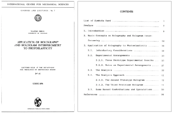
Fig. 1. Cover and Contents of the publication: Application of holography and hologram interferometry to photoelasticity, which contains the lecture notes of prof. Vlatko Brčić for the
lectures he held in 1974 at the internationally renowned Center for Mechanical Sciences in Udine, Italy (CISM) (Brčić, 1974)
Besides his engagement in education, professor Brčić was also a very active researcher, prominent theoretician and a member of several distinguished scientific societies and associations. He was a member of Yugoslav Society of Mechanics (the Chairman in the period: 1974-1978), Society of Applied Mechanics and Mathematics (Gesselschaft für Angewandte Mechanick und Mathematic, Germany), Society for Experimental Mechanics (USA), International Union of Theoretical and Applied Mechanics (IUTAM), etc. His theoretical work was mostly oriented to the problems of the Theory of Elasticity, Dynamics of structures and Experimental stress analysis of structures, which included the photoelasticity theory. Prof. Brčić contributed to these scientific areas through various publications, and his work was recognized worldwide. He was a guest professor at Wayne State University in Detroit, USA, in 1966-1967, and he participated in numerous international scientific conferences. There, he established many professional relations with the leading scientists in these areas of science and later on brought this knowledge to Yugoslavia and shared it with his colleagues. He was one of the pioneers in the field of photoelasticity in this region, and this method was just starting to develop at that time.
Theory of elasticity that were often encountered in practice. Thus, he had many successful collaborations with different institutes for stress analysis of materials and structures throughout the country, and these collaborations gave him a valuable feedback for his theoretical work. Many of the papers that Professor Brčić published were related to the investigations he conducted at the Institute for Hydraulics “Jaroslav Černi“ in Belgrade, Serbia. These papers were published in the periodic journal of the mentioned Institute, and they had a profound influence on the development and application of the photoelasticity method in this region.
The aim of this paper is to give an overview of the papers on the photoelasticity method and its application, that Prof. Brčić has published in the journal of the Institute for Hydraulics “Jaroslav Černi“, pointing out their significance and bringing the attention of a somewhat wider circle of researchers to the contribution of Professor Brčić to the development and practical application of this method.
2. The basic concepts of the photoelasticity method
The photoelasticity method is a well-established method for experimental testing of structures. It has been used successfully for decades and it has been thoroughly described and explored in literature, for example (Hedrih, 1988; Brčić & Čukić, 1988). Here, only the basic terms, principles and ideas will be presented, while a more detailed explanations and proof can be found in the mentioned literature.
According to the currently generally accepted theory, light has a dual nature – a corpuscular, and a wave-like. The photoelastic method is based on the wave theory of light, which assumes that light (visible to a human eye) is a part of the electromagnetic (EM) spectrum. In each point through which an EM wave passes, the intensity of the electric field and the intensity of the magnetic field vary, and if the wave propagates through an isotropic homogenous medium, vectors of these fields oscillate in two mutually perpendicular planes, but in directions that, in general case, vary in time and space. In Optics, the vector of the electric field is referred to as the light vector, and all further considerations presented here will be focused on it, while tacitly assuming the correspondent behaviour of the magnetic field vector.
If the light wave has a distinctive, constant frequency and wave length, this light is monochromatic, whereas if it is comprised of all possible perceptible wave lengths, the light appears to be white. Both of these are used in the photoelasticity method.
Regardless of its direction, the light vector in any point of space can be presented by its two orthogonal components in two mutually perpendicular directions, in the plane tangent to the wave front passing through that point. In this text, each light vector will be analysed with respect to its two components. As it has been mentioned, in general case, the light vector oscillates in various directions, stochastically. However, it is possible to force this vector to follow certain rules of change, thus obtaining polarized light. If the light vector oscillates only in one direction, then it has only one component and the light is linearly polarized. If the two components of the light vector oscillate with the same frequency, wave length and amplitude, but with a phase shift, the light is elliptically polarized, and if the phase shift is exactly one quarter of the wave length, the light is circularly polarized.
materials would have, and thus it is called the ordinary wave. The other one has a different refraction angle than the first one, so it is called the extraordinary wave. After these two waves exit the crystal, their light vectors oscillate in two mutually perpendicular directions, they have the same frequency, but are phase-shifted for a certain amount. These, optically active crystals have an optical axis. If the light vector of the light wave entering the crystal is of the same direction as the optical axis, there is no dual refraction, and only the ordinary refraction wave exists. The light vector of this ray oscillates in the direction of the crystal optical axis. Some of these crystals exhibit the dichroism property, that is, upon the dual refraction one of the refraction waves gets absorbed by the crystal much more than the other. If an optically active crystal absorbs the extraordinary wave completely, then the light wave that comes out of the crystal is linearly polarized, and its light vector oscillates only in the direction of the optical axis of the crystal. Crystals with such properties are called polaroids and they are used to obtain polarized light.
Certain materials become optically active if exposed to stress, and materials with this stress-induced optical activity are used to make models that can be analysed by the photoelasticity method. When stressed, these materials exhibit the birefringence property, meaning that they decompose a ray of polarized light passing through them into two rays with light vectors oscillating in two orthogonal directions. These directions are optical axes and their orientation depends on the deformations in the model. However, if the model is isotropic, relatively thin and stressed in its own plane, the lateral effects of Poisson’s ratio can be neglected and general spatial problem is reduced to a plane problem of Elasticity. Then, the directions of the optical axes correspond to the directions of principal stresses in the plane of the model, and only this type of model will be discussed here. The two refracted rays are phase-shifted and this phase-shift is usually expressed in terms of their relative wave length retardation δ as:
1 2
1 2
C d d f
where C is an optical coefficient of the material, d is the thickness of the material plate, λ is the wave length of the light wave, σ1 and σ2 are principal stresses, and fσ is the stress-optic coefficient
of the material. It is obvious that the stress-induced retardation δ depends on the stress state in the model, as well as on the wave length of the ray of the incoming light.
2.1 The photoelasticity method
The main idea in this method is to use optical activity of some materials to analyse the model and obtain information about the stress field in the tested structure. This is achieved with the use of a polariscope. There are two basic types of polariscope – the linear polariscope, which produces linearly polarized light, and the circular polariscope, producing circularly polarized light.
The model of the tested structure (M) is made of some transparent material possessing the stress-induced optical activity property and during the test it is put between P and A and the appropriate load is applied to it. When the polarized light from P reaches M, it gets split into two rays and, at each point of the model, light vector gets decomposed into two components in the direction of principal stresses present at that point. The two light vectors exiting the model experience a phase shift δ and they are mutually perpendicular, but at an angle β to the optical axes of P and A. The maximum intensity (amplitude) of the resultant light vector Imax is then:
2sin 2 sin2 2 max 0
l a
Fig. 2. Schematic representation of a linear polariscope
where a0 is the amplitude of the light vector entering the model, δ is the phase shift of the
passing through that point and this point will appear as yellow in the analyser. In the same way, points with different principal stresses will cancel different parts of the white spectrum, and points with the same difference in principal stresses will form lines of the same colour in the analyser field – hence the name isochromatics.
If the polarizer and analyser are kept crossed, but are both rotated for some angle, then the polarization cross shifts its angle to the tested model, and isoclinics will also transform - since now some other points of the model have principal stresses in the directions of the polarization cross. On the other hand, isochromatics will remain unchanged, since the rotation of the polarization cross does not affect the stress field in the model and principal stress differences remain the same at all points of the model. This is the basic way of differentiating the isoclinics from isochromatics if the monochromatic light is used. Figure 3 (Ramesh, Course on Experimental Stress Analysis) shows an example of fringes in a tested diametrically stressed circular disc. In Figure 3 a) through d) the results of a test with monochromatic light are presented, while Figure 3 e) through h) shows the results of the same test, but when white light was used.
By rotating the polarization cross and noting the corresponding isoclinics, one can obtain the map of isoclinics and derive the trajectories from it of the principal stresses throughout the model. On the other hand, isochromatics provide information only about the principal stress difference at various points of the model, but not the actual stress values. Thus, additional information has to be provided in order to determine the actual stresses, and there are several methods of achieving this – for instance: shear stress difference method, isopachic method and interferometry method (Doyle & Phillips), to mention a few. They will not be discussed here, but for more details the reader is referred to (Brčić & Čukić 1988), (Doyle & Phillips), (Ganesan, 2000). Here, it is only pointed out that isoclinics are used to obtain the principal stress trajectories, while isochromatics are used to calculate the actual values of the principal stresses.
a) b) c) d)
e) f) g) h)
Fig. 3. Fringes in a diametrically compressed disc; a)-d) fringes at monochromatic light and the inclination angle β=30o, 45o, 60o, 90o, e)-h) fringes at white light and the inclination angle
β=30o, 45o, 60o, 90o (Ramesh, Course on Experimental Stress Analysis)
2.2 Other types of polariscope
isochromatics can then be studied in more detail. This is enabled by the polariscope construction. A circular polariscope is similar to the linear one, but it has two additional elements. Namely, one birefringent plate is added between the polarizer and the tested model (Q1), and another one is
added between the model and the analyser (Q2). These plates split the incoming linearly polarized
light ray into two refracted rays with orthogonal light vectors, introducing them the phase shift proportional to the thickness of the plate. If the optical axes of the plate are at 45o to the incoming
light vector, the amplitudes of the refracted light vectors are the same, and if the thickness of the plate is such as to produce the retardation of the extraordinary ray of exactly one quarter of the wave length of the incident light, the light that exits the plate will be circularly polarized. Optically active plates of this kind are called quarter wave plates, and these are used in circular polariscope. The schematic representation of a circular polariscope is presented in Figure 4.
Fig. 4. A schematic representation of a circular polariscope
In this polariscope, usually a monochromatic light is used, since quarter wave plates need to be of different thickness to circularly polarize light of different wave lengths. It is also possible to circularly polarize white light, but with considerable losses in light intensity.
compensation and improvement methods are used (Pinit & Umezaki, 2007), (Ramji & Ramesh, 2008), which makes it very suitable for dynamical analysis. Comprehensive reviews on contemporary applications of the photoelasticity method in stress analysis are presented in literature (Ramji & Ramesh, 2008), as will be discussed later.
2.3 Optically active materials used for building the tested model
In photoelastic analysis, it is very important to choose the appropriate material for building the tested model. The material should, in general, be transparent and have a low stress-optic coefficient. It should also be mechanically and optically isotropic and homogenous, with high elasticity modulus and it should not creep excessively or change its property markedly with small variations of temperature. It should also be workable so it can be shaped and carved into the desired shape, but at the same time remain free of residual stresses (Ganesan, 2000).
Many materials satisfy these conditions, such as various types of glass, plastic, celluloid, rubber, gelatin, vinyl, polyester and epoxies, and they have been used in photoelastic model testing with great success (Ganesan, 2000). Among the ones that are most often used in practice are epoxy resins in form of Araldite B and D, glyptic resin Catalin, glass and Dancryl, and recently also some gelatin mixtures and Urethane rubber.
****
Since the time of prof. Brčić’s work, the photoelastic method for testing structures has been improved by including new technological advancements, and the process of testing has been made faster and more precise. However, the basic principles of the method are still the same, and the results and achievements of prof. Brčić and other researchers of his time are more admirable, since the tools they had at their disposal were considerably less sophisticated, but they, nevertheless, managed to use them competently and solved some very complex problems they met in their practice.
3. A brief overview of professor Brčić’s scientific activity
Professor Brčić was a productive researcher for his time. He published, in total, 70 papers in national and international scientific and engineering journals, 18 textbooks and lecture notes, and 4 plenary lectures at national and international conferences in Theoretical and Applied Mechanics. In 10 papers he discussed the photoelastic method and its application in stress analysis of structures, and these publications are of the main interest to this paper. Considering their topic, the mentioned papers can be divided into two groups.
The first group is comprised of the ones that concern the Theory of photoelasticity, exploring new possibilities of some optically active materials, improvement of the method and broadening its application to new problems. The following papers could be placed in this group: “O fotoelastičnom ispitivanju prostornih modela“ (On the photoelastic testing of the spatial models, 1960) (Brčić & Vidaković, 1960b), “Primena niskomodulnih materijala kod ispitivanja uticaja sopstvene težine” (The application of low-modular materials for testing the influence of self weight, 1968) (Brčić & Nešović, 1968), and “Prilog teoriji holografske interferometrije primenjene u fotoelastičnosti” (A contribution to the Theory of holographic interferometry applied in the photoelasticity, 1969) (Brčić, 1969).
1957) (Brčić, 1957), “Fotoelastično ispitivanje naponskog stanja kod gravitacionih brana sa otvorima“ (A Photoelastic testing of the stress state in gravity dams with openings, 1958) (Brčić, 1958), “Fotoelastično ispitivanje brane sa otvorima na elastičnoj podlozi“ (A Photoelastic testing of a dam with openings on an elastic base, 1960) (Brčić & Vidaković, 1960a), “Fotoelastično ispitivanje modela brane HE Bajina Bašta“ (A photoelastic testing of the model of the dam of the HE power plant Bajina Bašta, 1962) (Brčić, 1963), “Primena modelskih ispitivanja pri rešavanju problema hidrotehničkih konstrukcija“ (The application of model testing in solving problems of hydrotechnical structures, 1964) (Brčić & Jovanović, 1964), “Testing Prestressed Structures by Photoelasticity method” (1966) (Brčić & Pakvor, 1966), and “Fotoelastično ispitivanje dikontinualnih stena” (Photoelastic testing of discontinuous rocks, 1970) (Brčić & Nešović, 1970).
In the following text these two groups of prof. Brćić’s papers will be discussed separately, pointing out the essential ideas stated therein and their contribution to the development of the photoelasticity method.
4. Papers of prof. Brčić providing a theoretical contribution to the photoelasticity method
In the first group of his papers, Prof. Brčić discussed various possible improvements of the photoelasticity method as well as possibilities of widening the field of application of this method to some more complex problems.
Namely, the photoelasticity method in its original form was suited only to solve problems with the plane state of stress or deformation. This follows from the fact that it is possible, by using the maps of isoclinics and isochromatics, to differentiate only two of the three principal stresses at any point of the analysed model. However, in his research, Professor Brčić explored the possibilities of applying the photoelasticity method even to some “spatial” problems that included the general stress state. He did this mostly by using the method of stress freezing, and although he did not invent this method, he investigated it thoroughly in order to make it more accurate and reliable (Brčić & Vidaković, 1960b).
Another problem that arises when using the photoelasticity method, and that prof. Brčić was dealing with, is the problem of accounting for the self-weight of the structure. Since the analysed model is scaled to a much smaller size compared to the prototype, and it is almost always made from a different material and most often represents only a relatively thin section of the modelled structure, it is very difficult to analyse the influence of self-weight on such models. Prof. Brčić made an effort to solve this problem by making several separate models. One of them was made of some low-modulus material and it was used to determine the stresses induced by self-weight of the structure, while the effects of the predicted loads on the structure was determined by a standard procedure on another model made of some commonly used optically active material. Finally, the resultant stresses and deformations can be calculated by superposing these effects. However, finding an adequate material for a self-weight model is a considerable task even today, and prof. Brčić tested various materials and presented his findings in (Brčić & Nešović, 1968) in 1968. Here, he proposed several different materials for this purpose, but since the optical properties of these materials change in time, as well as in accordance with the loading conditions, for each material a time-dependent function of its properties had to be defined, and these are also included in the mentioned literature.
incorporate the holographic interferometry method enabled by the discovery of lasers and advances in this field of optics. Fusing these two methods made it possible to store the test data more efficiently, to get results more quickly and present them more conveniently than by the standard photoelasticity method alone (Brčić, 1969), which represented a considerable improvement of this method at the time. Prof. Brčić published papers on this subject in 1967 (Brčić, 1967) and 1969 (Brčić, 1969).
5. Publication regarding the practical application of the photoelasticity method
Professor Brčić has published most of his papers that concern practical application of the photoelasticity method in testing of structures in the journal of the Institute for Hydraulics „Jaroslav Černi” in Belgrade, Serbia, and since he usually found inspiration for his research in problems encountered in engineering practice, it is quite reasonable that a majority of these papers deals with the analysis of hydrotechnical structures, mostly the stress analysis of various dams.
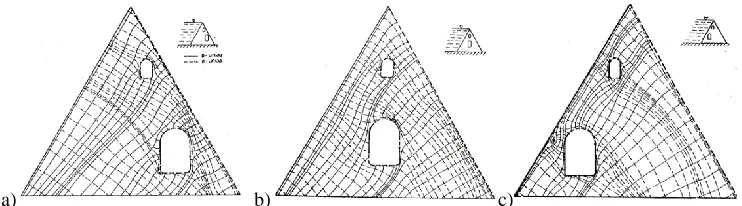
By testing the models made from optically active materials, prof. Brčić investigated variant structural solutions for gravity dams with openings in 1958, and through this research he proposed some guidelines regarding the optimal position of the openings inside the dam body (Brčić, 1958), (Brčić & Vidaković, 1960a). In Figure 5, the three variant solutions he analyzed are shown, depicting the openings located on the downstream side, on the centre axis of symmetry, and on the upstream side of the dam, as well as the corresponding maps of isochromatics for each of the variants. In Figure 6 the obtained principal stress trajectories are given, and it can be seen that the position of openings influences the stress state inside the dam significantly. It can also be seen that there are stress concentrations on the edges and in the corners of the openings and that stresses there are much higher than in the rest of the structure, so this parts should be treated as critical.
a) b) c)
Fig. 5. The variant structural solutions for the position of the openings in a gravity dam and the corresponding maps of isochromatics; a) openings on the downstream side of the dam, b) openings on the symmetry axis of the dam, c) openings on the upstream side of the dam (Brčić,
1958) (Brčić, 1958)
a) b) c)
Fig. 6. The principal stress trajectories for the three analyzed variant solutions; a) openings on the downstream side of the dam, b) openings on the symmetry axis of the dam, c) openings on
the upstream side of the dam; continuous line – σ1, dashed line – σ2 (Brčić, 1960a)
layers of various structure and properties. The model was made carefully, taking all the essential parameters into account, and the final tested model is presented in Figure 7a), followed by the corresponding map of isochromatics in the Figure 7b). Simultaneously, another model of the same geometry but with a continuous, isotropic rock was tested as a reference model, so that the influence of the discontinuities in rocks could be clearly distinguished. The principal stress trajectories for both the models are presented in Figure 8. From the figure it can be readily seen that the discontinuities have a large influence on the stress distribution, and this leads to a conclusion that the surrounding soil should be modelled as detailed as possible (if there are no apparent stress concentration points within the tested structure itself).
Fig. 7. The isochromatics for the model of the dam and the soil (Brčić, 1960) (Brčić & Vidaković, 1960a)
a) b)
Fig. 8. Principal stress trajectories in the model with: a) discontinuous rock, b) continuous rock; continuous line – σ1, dashed line – σ2 (Brčić & Nešović, 1970)
If used properly, photoelasticity can be a very valuable tool in the design process, since it gives the designer a possibility to test various structural solutions prior to the production stage, i.e. it is a convenient and relatively cheap way to optimize the structure. A good example of the use of photoelasticity method in the process of design and optimisation of a structure was given by prof. Brčić in Brčić & Pakvor, 1966. In this paper from 1966, a prestressed reinforced concrete pressure vessel was designed, and the influence of the proposed disposition of the prestressing cables was analyzed. For technical reasons, professor Brčić here again resorted to the superposition principle. Namely, two separate models were made and tested, one to capture the influence of the hydrostatic pressure from within the vessel, and the other to measure the influence of the prestressing. The effects were superposed to get the resultant stress field in the structure. The cross section of the tested structure is shown on Figure 9, while Figure 10 shows the two models for investigating the influence of the hydrostatic pressure and the prestressing cables. The first model included the whole cross section so the internal pressure could be inflicted, and the second model represented only a part of the cross section, thus making most of the symmetry and regular shape of the tested structure..
Fig. 9. The modelled cross section of the designed concrete pressure vessel; (for testing of the pressure cables influence only the shaded part of the section was modelled) (Brčić, 1966)
a) b)
Fig. 10. a) The model for testing the influence of the hydrostatic pressure, b) The model for testing the influence of the prestressing cables (Brčić, 1966) (Brčić & Pakvor, 1966)
As it turned out, the proposed disposition of the prestressing cables did not have the desired effect, on the contrary – it did not relieve the tension in concrete, it has even increased the tensile stresses in some regions of the vessel. Thus the use of photoelastic testing in the design process has prevented a costly mistake of producing a structure with the undesirable characteristics, and perhaps even an unreliable structure, and warned the constructors to reinvestigate their initial ideas and assumptions.
6. A more detailed preview of some results of prof. Brčić
In his research, prof. Brčić has investigated various aspects and possibilities of the photoelastic method, always trying to broaden the field of its application in solving problems of testing the structures that he encountered in his many years of engineering practice. As it has already been mentioned, this method, in its original form, was suited mostly for solving plane problems of Elasticity, but prof. Brčić was one of those who applied it also on the general spatial problems, mostly by using the method of stress freezing.
The most thorough example of the application of the photoelasticity method for solving a practical problem prof. Brčić gave in his publication (Brčić, 1963) from 1963, and here first a more detailed preview of the results he came to in the mentioned paper will be presented.
6.1 Photoelastic investigation on the HE Bajina Bašta dam model (Brčić, 1963)
a) b) c)
Fig. 11. The preliminary test of the massive head of the buttress; a) the tested model, b) the map of isoclinics, c) the principal stress trajectories in the model (Brčić, 1963)
In the preliminary tests, two models were tested. First a horizontal cross section of the massive head of the analysed buttress was modelled in scale 1:100 and tested with the photoelasticity method, in order to explore the state of stress inside the head. In the modelling process, some approximations had to be introduced - the geometry of the model needed to be somewhat simplified, and only the influence of the hydrostatic pressure was investigated, while the effects of the self-weight of the structure were not considered. The tested model is presented in Figure 11a), while the Figure 11b) presents the map of isoclinics and the Figure 11c) shows the obtained principal stress trajectories. The image of isochromatics was obtained with monochromatic light, and this image is given in Figure 12a), while Figure 12b) shows the map of isochromatics sketched based on their image.
a) b)
Fig. 12. Isochromatics in the model of the massive head of the buttress; a) the actual image in the polariscope, b) the map of isochromatics based on their image (Brčić, 1963)
a) b) c)
Fig. 13. The quantitative analysis of principal stresses in the buttress head; a) the adopted grid for FDM, b) the contours for maximum principal stress, c) the contours for minimum principal
stress (Brčić, 1963)
It should be noted here that the stresses obtained in this phase of testing are actually the secondary principal stresses (Brčić & Čukić, 1988), (Brčić, 1963), since the spatial effects are very high, but nevertheless neglected in the described plane testing of the model. Thus the obtained results should be taken only as descriptive, but they clearly show that the whole of the buttress head is in compression and that there is a stress concentration at the transition from the head to the buttress wedge.
a) b)
Fig. 14. The second model for preliminary tests – a vertical section of the buttress through its wedge, a) the tested model, b) the image of isochromatics (Brčić, 1963)
a) b) c)
Fig. 15. Secondary principal stresses in the model; a) stress trajectories, b) contours for maximum sec. principal stress, c) contours for minimum sec. principal stress (Brčić, 1963)
This model also represented the soil underneath the dam so the interaction between the structure and the soil could be simulated. In order model the elasticity modulus ratio of the dam and the soil in situ, the model of the dam was made of Plexiglas and the model of the soil was made of Araldit B with the addition of Thiocole LP 33 to soften it. However, the ratio on site was 20:1, but the ratio in the model was only 6.5:1, since the higher ratio would lead to very large deformations of the soil model. Nevertheless, the achieved ratio was enough to obtain the needed results. Another approximation was that again only the influence of hydrostatic pressure was investigated, while neglecting the effect of the structure self-weight. The quantitative stress analysis was once again conducted by solving Laplace differential equation for stress potential. However, this time the field of the model was divided in two parts in order to exclude the zone of the dam-soil boundary. The excluded zone is labelled with lines 1-2, 3-4 and 4-6 in Figure 14a), and the differential equation was solved by the FDM. The secondary principal stress trajectories are presented in Figure 15a), while Figure 15b) and 15c) show contours of the secondary principal stresses.
a) b)
Fig. 16. The spatial model for stress freezing tests; a) the model of the dam buttress, b) the schematics of model slicing after the stress freezing (the shaded rectangles mark the slice
positions) (Brčić, 1963)
spatial model and the position of the taken slices is shown. The soil was not modelled, since the preliminary tests showed that its influence is not significant.
In these tests, again the same approximations were introduced – the influence of the self-weight was neglected and the zone at the dam-to soil boundary was not considered in the stress analysis. The vertical slice through the buttress wedge was rated as crucial and it was studied in most detail. The quantitative stress analysis for this slice was conducted by numerically solving Laplace’s equation for stress potential by FDM. The adopted grid and boundary conditions are presented in Figure 17a), while the secondary principal stress contours are shown on Figure 17b) and 17c).
a) b) c)
Fig. 17. Quantitative stress analysis of the slice through the buttress wedge, a) the adopted grid and boundary conditions for FDM, b) the maximum secondary principal stress contours, c) the
minimum secondary principal stress contours (Brčić, 1963)
After a detailed testing, the proposed design of the dam was rated as satisfying and the construction of the dam was approved. The data acquired through the photoelastic testing of the buttress models had a crucial role in the assessment of the proposed solution, since it gave direct insight into the state of stress inside the designed dam. However, due to the approximations made in the modelling process, prof. Brčić suggested in this paper that these results should be taken with up to 10% relative error, but that was enough to experimentally substantiate theoretical calculations. It should be mentioned that this hydro-electrical dam still supplies considerable amount of electrical power to the electrical power systems in Serbia, and it has been working flawlessly for the past five decades.
Professor Brčić was very aware of the limitations and shortcomings of the photoelasticity method, but he has always strived to improve the method and overcome the problems that would arise in model testing. A good example for this was the investigation of various possibilities of testing the influence of the structure self-weight, that was very difficult to analyse in that time. Prof. Brčić has presented some of his ideas regarding this topic in publication (Brčić & Nešović, 1968) in 1968.
6.2 The application of low-modular materials for testing the influence of self-weight (Brčić & Nešović, 1968)
materials used for photoelastic analysis of structure self-weight, both elastic and inelastic ones. Among others, he mentioned gelatinous and glycerin-based materials, etil-cellulose, poliefirnic and epoxy resins as the most commonly used ones.
The common characteristic of these materials is that they all have relatively low values of the elasticity modulus, and consequently they experience relatively large deformations, even due to the self-weight load only. Moreover, their mechanical and optical properties depend on elapsed time, temperature changes and stress conditions, so that for each material a property function with respect to these variables needs to be defined in order to use the material in a stress-optic analysis. Prof. Brčić found that for elastic low-modulus materials, foremost gelatin and composite materials based on it, the elastic modulus decreases with time, while the stress-optic coefficient increases (Brčić & Nešović, 1968). For inelastic materials, the plastic deformations due to creep are very large, often even multiple times larger than the elastic deformations, and for these materials a “creep curves”, that is, a maximum deformation-time curves for maximum stress levels, need to be defined. Prof. Brčić provided such curves for Gelatinous material he used in tests, and these charts are presented in Figure 18a). For viscoelastic materials, a rheological model can be defined and deformation values for any given max. shear stress value can be calculated for any point in time, making it possible to theoretically evaluate experimental results. The rheological model prof. Brčić used in his research is presented in Figure 18b)
a) b)
Fig. 18. Maximum shear deformation to time dependences with respect to the maximum shear stress in the material for constant stress conditions; a) experimental curves, b) theoretical curve
and the rheological model used (Brčić & Nešović, 1968)
a) b)
Fig. 19. Testing the self-weight influence on the Salakovica dam; a) the gelatinous model, b) stress results (Brčić & Nešović, 1968)
The photoelastic analysis is made more complicated for use by the fact that many images have to be acquired and much image processing is necessary in order to obtain the complete map of isochromatics and isoclinics. In the time that prof. Brčić done most of his research, lasers were invented and the holography was developed. There were attempts to apply the newly discovered holography and holographic interferometry to the existing photoelastic method in order to make the testing process easier and faster. Prof. Brčić took part in these efforts to improve the photoelastic method, and he presented his contribution in the paper (Brčić, 1969).
6.3 A contribution to the Theory of holographic interferometry applied in the Photoelasticity (Brčić, 1969)
Prof. Brčić actively participated in inventing and developing the method for application of the holographic interferometry in photoelasticity, in collaboration with many scientists from around the world, and this paper was a product of one such collaboration with R.L. Powel and J.D. Hovanesian during 1967 at Ann Arbor, Michigan, USA. Although the hologram had been invented in 1948, holographic interferometry was introduced in photoelasticity as late as in 1960s, and prof. Brčić was one of the pioneers in this field, publishing several original and co-authored papers and continuing previous work of some researchers (Stetson & Powel, 1966; Brčić, 1967; Hovanesian, Powell & V 1968; Fourney, 1969), but he presented his main contribution in the paper that is previewed here.
In this paper he gave a brief overview of the holography and holographic interferometry method, that is, the basic principles of recording a holographic image of an object and reproducing its hologram.
plane problem of Elasticity, since the actual principal stress values can then be very easily calculated in each point of the model.
This method is discussed in the paper in much detail, where prof. Brčić also provided the equations needed to successfully apply holography in photoelastic testing of structures. This solution to the plane problem of Elasticity is much more elegant, easier and faster to use in practice, and prof. Brčić sensed that it could be applied also to the spatial problems, as well as in the photoplasticity and photoviscosity, methods that were only starting to develop back then, and that technological advances in optics and lasers would enable the application of holographic interferometry even in photoelastic testing in Dynamics of structures (Brčić, 1969). Time proved him right, since now this method is widely used in experimental testing of structures, both in static and dynamic problems.
7. Concluding remarks
The Photoelasticity method is still used in testing the structures even today, although the advances in technology imposed the use of criteria and instruments somewhat different than those used by prof. Brčić, but the essential ideas and principles remain the same. For instance, now there are much more powerful and distinctive light sources and recording instruments at our disposal so that the maps of isoclinics and isochromatics can be captured in much more detail (Ajovalasit, Petrucci, & Scafidi, 2015) and also some new optically active materials are often used (Ramesh & Ramakrishnan, 2016), but the procedure is still the same. The main difference in today’s testing practice, compared to the time of prof. Brčić’s research, is that now digital polariscope is used almost exclusively, and image acquisition and processing is done automatically, largely utilizing the numerical power of computers. This means that test data is obtained faster and it is more precise, but the theory and underlying concepts of the photoelasticity remain the same. Further research and development of the method was mostly related to the automation of the data acquisition and analysis process, so that various new scanning schemes were developed (Digendranath, Binu, P, & Annamala, 2015), (Kale & Ramesh, 2013), (Yao, Jian, Xu, Jin, & Yeh, 2005), (Digendranath, Jeby, & Annamala, 2014), (Ramakrishnan & Ramesh, 2017a), (Ramakrishnan & Ramesh, 2017b) and new methods for extracting the stress data from the acquired images have been presented, for instance (Ramji & Ramesh, 2008).
shows a map of isochromatics in two models of composite materials, and Figure 21 shows the stress state analysis in a gravity dam done in 2002 (Feng, Laishou, Junhua, Chun, & Yue, 2002). The advancement in image quality is obvious, but similarity with the research of prof. Brčić is also very striking.
a) b)
Fig. 20. Map of isochromatics in two contemporary model testing; a) Model of a new composite material (Liebig, Leopold, & Schulte, 2013), b) Model for testing of optical activity
of glass (Ramesh & Ramakrishnan, 2016)
Fig. 21. Contemporary stress state analysis in a gravity dam (Feng, Laishou, Junhua, Chun, & Yue, 2002)
Finally, it can be said that theory and practice complement each other – advances in theory improve practical procedures and open new possibilities, while practical research and investigations provide the completion, verification and motivation for further theoretical considerations. Thus, researchers should aspire to unite these two qualities, and to add to that human qualities and virtues. That t is what distinguishes truly great people. This is very hard to achieve and such people are rarely met. However, there is no doubt that professor Brčić was one of those who succeeded.
AcknowledgementsParts of this research were supported by the Ministry of Education, Science and Technological Development of Republic of Serbia through Mathematical Institute SASА Belgrade Grant ON174001 “Dynamics of hybrid systems with complex structures. Mechanics of materials”.. Authors of this paper are very grateful to Professor Stanko Brčić, son of Professor Vlatko Brčić, for providing numerous papers written by his father and published in publications of the Institute for Hydraulics “Jaroslav Černi“ in Belgrade.
References
(2003) FACTA UNIVERSITATIS, Series: Mehanics, Automatic control and Robotics, 3(13). Ajovalasit, A., Petrucci, G., & Scafidi, M. (2015). Review of RGB photoelasticity. Optics and
Lasers in Engineering, 68, 58-73.
Brčić V (1957). Jedan primer primene metode fotoelastičnosti. Saopštenja Instituta „Jaroslav Černi“, 7, 28-35.
Brčić V (1958). Fotoelastično ispitivanje naponskog stanja kod gravitacionih brana sa otvorima. Saopštenja Instituta „Jaroslav Černi“, 12, 1-22.
Brčić V (1963). Fotoelastično ispitivanje modela brane HE Bajina Bašta. Saopštenja Instituta „Jaroslav Černi“, 29, 1-15.
Brčić V (1969). Prilog teoriji holografske interferometrije primenjene u fotoelastičnosti. Saopštenja Instituta „Jaroslav Černi“.
Brčić V (1974). Application of Holography and Hologram Interferometry to Photoelasticity. Lectures held at the Department for Mechanics of Deformable Bodies. Udine, Italy: International Centre for Mechanical Sciences.
Brčić V & Čukić R (1988). Eksperimentalne metode u projektovanju konstrukcija. Beograd: Građevinska knjiga.
Brčić V & Jovanović L (1964). Primena modelskih ispitivanja pri rešavanju problema hidrotehničkih konstrukcija. Saopštenja Instituta „Jaroslav Černi“, 30, 17-29.
Brčić V & Nešović M (1968). Primena niskomodulnih materijala kod ispitivanja uticaja sopstvene težine. Saopštenja Instituta „Jaroslav Černi“, 29-36.
Brčić V & Nešović M (1970). Fotoelastično ispitivanje dikontinualnih stena. Saopštenja Instituta „Jaroslav Černi“, 31-49.
Brčić V & Pakvor A (1966). Testing Prestressed Structures by Photoelasticity method. Saopštenja Instituta „Jaroslav Černi“, 13(37), 11-16.
Brčić V & Vidaković M (1960a). Fotoelastično ispitivanje brane sa otvorima na elastičnoj podlozi. Saopštenja Instituta „Jaroslav Černi“, 17, 25-28.
Brčić V & Vidaković M (1960b). O fotoelastičnom ispitivanju prostornih modela. Saopštenja Instituta „Jaroslav Černi“, 17.
Calvert G, Lesniak J, & Honlet M (2002). Applications of modern automated photoelasticity to industrial problems. Real-Time Stress Monitoring, Insight, 44(4), 1-4.
Digendranath S, Binu T, P J, & Annamala P (2015). Novel calibration and color adaptation schemes in three-fringe RGB photoelasticity. Optiics and Lasers in Engineering, 66, 320-329.
Digendranath S, Jeby P, & Annamala P (2014). A modified regularized scheme for isochromatic demodulation in RGB photoelasticity. Optiics and Lasers in Engineering, 61, 39-51. Doyle J, & Phillips J. (n.d.). Manual on Experimental Stress Analysis. Society for Experimental
Mechanics.
Dubey V, & Grewal G (2010). Efficacy of photoelasticity in developing whole-field imaging sensors. Optics and Lasers in Engineering, 48, 288-294.
Feng W, Laishou L, Junhua Z, Chun Y, & Yue W (2002). Research on the effect of bedrock upon the stress of a gravity dam bulk by the photoelastic method. Journal of Materials Processing Technology, 123, 236-240.
Fourney M (1969). Application of Holography to Photoelasticity. Experimental Mechanics. Frocht M (1951). Photoelasticity. New York.
Ganesan T (2000). Model Analysis of Structures. India: Univerities Press.
Hedrih, K. (Stevanović) (1988). Some Chapters in Theory of Elasticity. Niš, Serbia: Faculty of Mechanical Engineering, University of Niš.
Hedrih K (Stevanović) (1991). Zbirka rešenih zadataka iz Teorije elastičnosti. Beograd: Naučna Knjiga.
Hedrih K (Stevanović), & Jovanović, D. (1991). The stress state of the elliptical-annular plate by the complex variable function and conformal mapping method. Theoretical and Applied Mechanics, 17.
Hedrih K (Stevanović) & Perić, L (1992). Application of the complex variable function to crack problem in the piezoelectric material. Theoretical and Applied Mechanics, 18.
Hedrih K (Stevanović) & Perić, L (1996). Stanje napona i stanje deformacija u piezoelektričnom materijalu u okolini vrha prsline za slučaj ravne deformacije. Tehnika-Mašinstvo, 45, M50-M56.
Herih K (Stevanović), Jecić S & Jovanović D. (1990). Glavni naponi u tačkama konture eliptičko-prstenaste ploče ravno napregnute parovima koncentrisanih sila. Tehnika, Mašinstvo, 8-20. Hovanesian J, Powell R, & V B (1968). A New Stress-optic Method: Stress-Holo-Interferometry.
Experimental Mechanics.
Kale S & Ramesh K (2013). Advancing front scanning approach for three-fringe photoelasticity. Optics and Lasers in Engineering, 51, 592-599.
Liebig W, Leopold, C, & Schulte K (2013). Photoelastic study o stresses in the cincinity of a unique void in a fibre-reinforced model composite under compression. Composite Science and Technology, 84, 72-77.
Patil P, Vyasarayani C & Ramji M (2017). Linear least squares approach for evaluating crack tip fracture parameters using isochromatic and isoclinic data from digital photoelasticity. Optics and Lasers in Engineering, 93, 182-194.
Pinder J, J.J, & Jovanović D (1997). Electronic Techniques in Isodyne Stress Analysis: Part 2. Illustrating Studies and Discussion. Experimental Mechanics, 37(2), 106-110.
Pindera, J, Josephson, J., & Jovanović, D. (1997). Electronic Techniques in Isodyne Stress Analysis: Part I. Basic Relations. Experimental Mechanics, 37(1), 33-38.
Pinit P, & Umezaki E (2007). Digitally whole-field analysis of isoclinic parameter in photoelasticity by four step color phase-shifting technique. Optics and Lasers in Engineering, 45, 795-807.
Ramakrishnan V & Ramesh K (2017a). Scanning schemes in white light Photoelasticity – Part I: Critical assessment of existing schemes. Optics and Lasers in Engineering, 92, 129-140. Ramakrishnan V & Ramesh K (2017b). Scanning schemes in white light Photoelasticity – Part
II: Novel resolution guided scanning scheme. Optics and Lasers in Engineering, 92, 141-149. Ramesh K (n.d.). Course on Experimental Stress Analysis. India: IIT Madras.
Ramesh K & Ramakrishnan, V. (2016). Digital photoelasticity of glass: A comperhensive review. Optics and Lasers in Engineering, 87, 59-74.
Ramji M & Ramesh K (2008). Whole field evaluation of stress components in digital photoelasticity – Issues, implementation and application. Optics and Lasers in Engineering, 46, 257-271.
Stetson K & Powel R (1966). Hologram Interferometry. J. Opt. Soc. Amer., 56. Wolf H (1961). Spannungsoptik. Berlin: Springer.