Volume-5 Issue-2
International Journal of Intellectual Advancements
and Research in Engineering Computations
Virtual touch screen based library book accessing system
Mr R.S Kamalakannan1
1. Assistant professor of Shree Venkateshwara Hi-Tech Engineeringg College Buvaneswaran J2,keerthana C3, Jency P4, Vidhya B5.
2,3,4,5. Student of Shree Venkateshwara Hi-Tech Engineering College
Email: [email protected]
ABSTRACT-The use of embedded systems has a wide capabilities and features especially in smart home. Nowadays there is a demand for smart home automation access via virtual reality. This project mainly focuses the owner to accesthe system via virtual reality and controls the robot movement. In this project, the design and implementation of virtual reality at a low cost yet a flexible, feasible and secure virtual reality based robot movement control. This work also demonstrates the use of virtual reality in the context of the appliance control. Virtual reality can be used in a conventional manner to simulate the behavior of a system, but also in parallel with the real system to improve quality control. Experimental results show
the effectiveness of the proposed
architecture in a successful manner.
Key Word-Virtual reality, Robot movement, Wireless communication.
I. INTRODUCTION
The main aim of the project is to design a system which will be used to deliver the book from library to user with help of virtual touch screen. In the current scenario most of the people did not came to library. Because of they have did not
patience to searching the book in the library. In the modern society library contains lots of books based on many topics. Instead of that we should have very difficult to searching a book. It takes lot of searching time.
At the time to overcome this problem we introduced virtual touch buttons using projector and camera. In this method large interactive display with virtual touch buttons on a pale colored flat table. Touching any place on the virtual projection the preprogrammed process will be done. In the virtual touch screen only accepted human’s sense otherwise it will be neglected. The process will be done with X, Y co-ordinates. The camera sense the X, Y co-ordinates of virtual display.
II. HARDWARE ARCHITECTURE
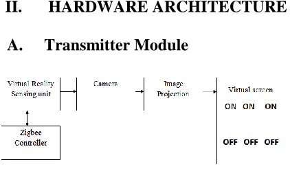
A. Transmitter Module
Fig. 1. Transmitter block diagram
This project consist of the arduino Microcontroller, virtual touch screen sensor, interfacing unit of sensor to receiver.
B. Virtual touch screen sensor
The concepts behind virtual reality are based upon theories about a long held human desire to escape the boundaries of the ‘real world’ by embracing cyberspace. Once there we can interact with this virtual environment in a more naturalistic manner which will generate new forms of human-machine interaction (HMI). The aim is to move beyond standard forms of interaction such as the keyboard and mouse which most people work with on a daily basis.
This is seen as an unnatural way of working which forces people to adapt to the demands of the technology rather than the other way around. But a virtual environment does the opposite. It allows someone to fully immerse themselves in a highly visual world which they explore by means of their senses. This natural form of interaction within this world often results in new forms of communication and understanding.
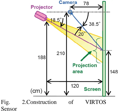
C. Construction of virtual sensor
Our touch screen is automatically initialized when the system is invoked. First, the relationship between the projector and the camera is calibrated to let the system know the button positions. This task is done by having the camera view a projected chessboard pattern. The second step of initialization is to acquire virtual button images. VIRTOS can have more than one touch button, each of a different color. The projector projects the various buttons to their positions on the screen, and the system memorizes each button-only image from the camera input
Fig. 2.Construction of VIRTOS Sensor
This project aim is to make large, easy-to-install, economical interactive displays; therefore, we use a front projector and a nearby camera. A hand touch on the screen is detected by the area of the shadow cast by the user’s hand. The key idea is that the shadow color does not depend on the projected color. The issue is when and how to alter the button color to capitalize on this idea without sacrificing usability. Our virtual touchscreen system, called VIRTOS, is designed to function in a space where ambient light conditions may change. VIRTOS continually monitors the touch area and when a large foreground covers and stops on the button, the color of the projected touch button is altered briefly in order to distinguish the shadow from the hand.
D. ZigBee
Initially, a GUI application runs on the system, which stimulator the functioning of the virtual reality projector and the camera. One needs to pre-define the necessary operational functions in order to make use of it while performing an action on the desired device. When the virtual reality projector is ready to use, it projects the 2d image on any surface. The projected is image can be Viewed by the user from a greater distance. The image would be crystal clear. The user by default interrupts the ray falling on the surface by hand movement in order to perform any kind of operation. The camera then captures the action made by the user. The GUI application recognizes the sudden interruption and there by insisting the ZigBee controller to transmit the signal ones a network.
The ZigBee receiver placed on a far-away end, receiver the transmitted signal. The signal is then transmitted to a circuit board consisting of a step-down transformer, bridge rectifier, capacitor, voltage regulator, MAX 232 IC, relay circuit, reset switch and PIC microcontroller. In the circuit, the signal
first passes through a step-down
transformer. The step-down transformer is basically used to cut down power from 230v to the required 12v dc. After passing through the step-down transformer, the signal passes through a bridge rectifier which rectifies the voltage from 12v to 15 dc. The signal further passes through the capacitor, a change storage device, which filters the 5v dc.
It also has an optional super frame
structure with a method for time
synchronization. In addition to this it is recognized that some messages need to be given a high priority. To achieve this, a guaranteed time slot mechanism has been incorporated into the specification. This enables these high priority messages to be
sent across the network as swiftly as possible.
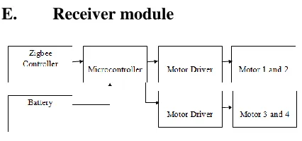
E. Receiver module
Fig. 3. Receiver diagram
The ZigBee receiver acquires the signal from the transmitter by the means of wireless network. The signal is then transmitted to the step-down transformer where the power is reduced to the specified ratio. This transformer is further connected to two circuits namely relay circuits and PIC Microcontroller parallel. There alone mentioned two circuits are interlinked to a MAX232 IC. The relay circuit is responsible for the operation of various devices connected to it.
F. Arduino
The Arduino Microcontroller is used in this process for comparing biomedical sensor value with the threshold value and send signal accordingly .A microcontroller board, contains on-board power supply, USB port to communicate with PC, and an Atmel microcontroller chip. It simplify the process of creating any control system by providing the standard board that can be programmed and connected to the system without the need to any sophisticated PCB design and implementation. It is open source hardware, anyone can get the details of its design and modify it or make his own one himself.
board will be powered by the USB cable and the code can be uploaded and communicated with the Arduino board. The power connector is used when only the power is needed for the Arduino. A normal transformer (power adapter) in the range from 6V to 24V can also be used to power it. The Arduino can also run on batteries.
Fig. 4. Arduino board
The reset switch is used to reset any program on the Arduino to start from its beginning. On Arduino older than the Diecimila version of the Arduino, the reset button needs to be pushed every time uploading the code.
G. Universal
asynchronousreceiver/transmitter
A universal asynchronous
receiver/transmitteris a type of
"asynchronous receiver/transmitter", a piece of computer hardware that translates data between parallel and serial forms. UARTs are commonly used in conjunction with other communication standards such as EIA RS-232. A UART is usually an individual (or part of an) integrated circuit used for serial communications over a computer or
peripheral device serial port. UARTs are
now commonly included in
microcontrollers. A dual UART or DUART
combines two UARTs into a single chip. Many modern ICs now come with a UART that can also communicatesynchronously; these devices are called USARTs.
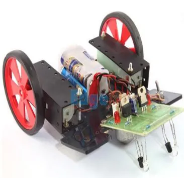
H. Robot
An array of sensor is used to detect the line. Based on the status of sensors, special circuit or controller decides the position of line and also the required direction of motion required to follow the line. Motor driver circuit is used to ON/OFF the LEFT/RIGHT motors of the robot to provide desired motion.
Fig. 5. Line follower robot mechanism
used a8051 Microcontroller, which makes the Robot Autonomous. We have used some electronic components viz. Motor Driver IC, Comparator, Voltage Regulator.For setting the communication between the robots, we use a infrared emitters which is mounted at the tail of line following robot.
They are uniformly spaced apart at a distance of 0.8 cm. The infrared sensors have the quality that they are unidirectional i.e. they emit the light in a straight line. So, by using this property, we used them as the communication network . For detecting, we use three detector in each of the two other robot . These detectors are mounted in the middle of their front. They are uniformly spaced apart at a distance of 0.8 cmThey are usually set in such a way that when line following robot move in a curved path , the angle made by the emitter to both the detector is 120 degree . Hence , by the use of this communicatonbehaviour , we are able to make our project successfully .
III. RESULTS
It has sources, signal generators,
measurement and analysis tools
like oscilloscope, voltmeter, ammeter etc., probes for real time monitoring of the parameters of the circuit, switches, displays, loads like motors and lamps, discrete components like resistors, capacitors, inductors, transformers, digital and analog Integrated circuits, semi-conductor switches, relays, microcontrollers, processors, sensors etc. ARES offers PCB designing up to 14 inner layers, with surface mount and through hole packages.
IV. CONCLUSION
This project examines the virtual hand button interaction in order to control the Robot movement using 2D virtual image. It replaces the need of real system
i.e. physical devices. The main advantage of this system over physical control is flexibility & easy to approach. Virtual buttons are used without a physical mock-up to make the virtual reality operator independent. This system reduces the complexity of the physical switches which were earlier used. In terms of long spells, it appears to be less costly than the existing one.
V. REFERENCES
1. Audet, S., Okutomi, M., and Tanka,
M. (2012). Augmenting moving planar Surfaces Interactively with Video projection and a Color
Camera. IEEE Virtual
reality(VRW’12), pages 111-112.
2. Borkowski, S., Letessier, J., and Crowley, J. L. (2004). Spatial Control of Interactive Surfaces in an Augmented Environment. EHCI/DS-VIS Lecture Notes in computer science, Volume. 3425, pages 228-224.
3. Brutzer, S., Hoferlin, B., and
Heidemann, G. (2011).Evaluation of Background Subtraction Techniques for Video Surveillance. IEEE Conference on Computer Vision and Pattern Recognition (CVPR ‘11), pages 1937-1944.
4. Dai, J. and Chung, R. (2012).
Making any planar surface into a touch-sensitive display by a mere projector and camera. IEEE Conf. on
Computer Vision and Pattern
Recognition Workshops (CVPRW ‘12), pages 35-42.
Interactive Tabletop System with a Markerless Gesture Interface for Robot Control. IEEE Conference on Robotics and Biomimetics (ROBIO ‘11), pages 2037-2042.
6. Kale, A., Kenneth, K., and Jaynes, C. (2004). Epipolar Constrained User Pushbutton Selection in Projected Interfaces. IEEE Conference on
Computer Vision and Pattern
Recognition Workshops
(CVPRW‘04), pages 156-163.
7. Lech, M. and Kostek, B. (2010). Gesture-based Computer Control System applied to the Interactive Whiteboard. 2nd International
Conference on Information
Technology (ICIT ‘10), pages 75-78.
8. Park, J. and Kim, M.H. (2010). Interactive Display of Image Details using a Camera-coupled Mobile Projector. IEEE Conference on
Computer Vision and Pattern
Recognition Workshops (CVPRW ‘10), pages 9-16.
9. Wilson, D. (2005). Playanywhere: a
compact interactive tabletop
projection-vision system. Proc. 18th ACM Symposium on User Interface Software and Technology (UIST ’05), pages 83-92.
10. Winkler, S., Yu, H., and Zhou, Z. (2007). Tangible mixed reality
desktop for digital media