Journal of Engineering Sciences, Volume 5, Issue 2 (2018), pp. D 15–D 20 D 15 JOURNAL OF ENGINEERING SCIENCES
УРНА ІН Н РНИХ НАУ
УРНА ИН Н РНЫХ НАУ
Web site: http://jes.sumdu.edu.ua
DOI:
10.21272/jes.2018.5(2).d3
Volume 5, Issue 2 (2018)UDC 629.33
Design and Analysis of Connecting Tie Rod Assembly for Automotive Application
Aravindaraj E.1, Natrayan L.2*, Santhosh M. S.3, Kumar M. S.21
Sri Manakula Vinayagar Engineering College, Mannadipet, 605 107 Pudicherry, India;
2
VIT University, Chennai, 600 127 Tamil Nadu, India;
3 Selvam College of Technology, Salem Road (NH 7), Pappinaickenpatti, Namakkal, 637 003 Tamil Nadu, India
Article info: Paper received:
The final version of the paper received: Paper accepted online:
April 7, 2018 June 29, 2018 July 3, 2018
*Corresponding Author’s Address:
[email protected]
Abstract. The tie rod end is one of the most elementary parts of a steering mechanism, which has direct and cru-cial importance in terms of driving safety. The tie rod end is used to ensure that the wheels are aligned. It provides the adjustment for the wheel to align and keeps the tires free from wearing out on the inner as well as outer edges. Hence the functioning of the tie rod is crucial for steering as well as suspension performance of the vehicle. Today’s world is competitive. Market demands the advanced technology at a lower price. This reflects in making the technology cheaper. Hence every industry determined for the cost-effective product at a lower price and within minimum period for ‘time to market. This puts a lot of pressure on engineers to consistently strive to design the more effective prod-ucts at the lower price. The work is focused on the functioning of the tie rod. Generally, tractor connecting tie rod gets failed due to the overload applications. This paper focuses on modifying the old tie rod design and material. Fi-nally, analysis the load causes of existing and modified design using ANSYS software. This modelling approach, the stress variations and deformation characteristics of each component are investigated for high operational loading conditions.
Keywords: thru-hole, clamp structure, front axle, ANSYS, deformation.
1
Introduction
Tie rod ends support (Figure 1) thru the steering of a vehicle and variety it possible to capture a tire. These devices occur in pairs on each tire. This sanctions for cornering and angling of the tire minus affecting too much torque on the trundlenopestaple how deep the sei-zure [1]. Tie-rod is certain as driving adherent for slant-ing the panel (along with panel mountslant-ing frame) from horizontal to vertical position and vice versa. In principal, tie-rod will have essential coupler with nail rods on sides, one through left hand thread and another through right hand thread [2]. The coupler has identical threads to put up these eased tie rods [3]. On spinning the coupler is turned, together the rods will spread or withdraw based on the trend of rotation of coupler. The ends of the rods are moreover eye or fork expiration type [3, 4].
Further research will be aimed at research the adjusta-ble front axle with adjustaadjusta-ble tie rod (Figure 1).
This origination relays to a tractor and more specifical-ly to unregulating front axle for a row crop farm tractor. In farm tractors of the row produce type it is crucial to afford for widening and narrowing the stamp of the
ambi-tion wheels where a three wheel tractor is fretful [5]. A four wheel rumpus crop tractor requires that both front and rear wheels be adjustable squarely, in directive to travel between the plants in the rows [6]. The peak com-mon scheme of varying the width of the wheel tread on ruckus crop tractors currently is to dispose the wheels hubs and tire rims in such routine that by reversing the wheels in relative to the hubs the stamp may be amplified or narrowed [7]. While the development above described may perform to be artlessearnings of amending the stride of the wheels of the tractor, however such amending mechanism fills a long desired want of stingily and easily altering the width of the tread of façade wheels of row crop tractors [8].
D 16 MECHANICAL ENGINEERING: Dynamics and Strength of Machines
2
Research Methodology
2.1
EN8 carbon steel material
EN8 is typically abounding organic but can be sup-plied to edict in the stabilized or finally heat salted (ap-peased and tempered to “Q” or “R” properties for off-putting ruling subdivisions up to 63 mm), which is ample for a widespread range of applications. EN8 is suitable for the assembly of quantities such as general-tenacity axles and shafts, gears, bolts and studs [6, 9]. It can be auxiliary hardboiled typically to 50–55 HRC by initiation processes, producing modules with enriched wear re-sistance. For such tenders the use of EN8D (080A42) is prudent. EN8 in its heat frozen rehearses possesses virtu-ous homogenvirtu-ous metallurgical structures, philanthropic unfailing machining properties [9]. Virtuous heat treat-ment grades on segtreat-ments grander than 63 mm may still be attainable, but it should be illustrious that a fall-off in mechanical properties would be superficialpotential the epicentre of the bar [10, 11]. Table 1 gives mechanical properties of material.
Table 1 – Material Properties
Material Yield strength, N/mm2
EN8 465
EN8D 443
EN5D 451
EN5C 438
When compared to mechanical property and cost EN8 is the best one for design the product and economical one [12].
2.2
Existing thru-hole design parts
The previous research papers are useful for deciding the analysis strategy. There were numerous conference papers, reference manuals, book by Robert cook Con-cepts and applications of FEA will be helpful for the project. From some of the research work it is being ob-served that the existing thru hole design model.
The existing geometrical model is created as a solid works 2016 software and analysis in ANSYS Work-bench, The geometrical model constitutes of the socket (Figure 2), radial ball joint (Figure 3), tube (Figure 4) and axle ball joint (Figure 5).
While neglecting the parts that are thought as negligi-ble in the analysis. Figure 6 shows that existing tie rod design using solid works software.
2.3
Problem identification
In the existing design nut and bolt joints are used to connect the socket and tube, so it can’t withstand more compressive load and tensile load. It leads to bend which causes breakage in the tie rod. Also, the thru-hole design is applicable to load only below 2 000 kg and when the load increases the tie rod bends. So it cannot withstand more than 2 500 kg tensile load and compressive load.
Figure 2 – Socket
Figure 3 – Radial ball joint
Figure 4 – Tube
Figure 5 – Axle ball joint
Figure 6 – Existing tie rod design
2.4
Designs of tie rods
2.4.1 Proposed new design
The tie rod is continuously under random loading there can be more chances of developing the cracks at the criti-cal areas and chances of failure. Also the manufacturing process of this existing design is critical and time con-suming. Hence it is necessary to make the design simple and cost effective such that it gives overall effectiveness in terms of weight, cost, load carrying capacity and easy of manufacturing process. The main task in this study is to find the critical buckling load for the existing design. Observe the deformation and stresses induced in the Tie rod. Set up the benchmark for the proposed design.
Journal of Engineering Sciences, Volume 5, Issue 2 (2018), pp. D 15–D 20 D 17
Figure 7 – Proposed new design
2.4.2 Existing model tie rod analysis
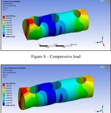
The existing tie rod model has carried out static analy-sis using EN8 carbon steel material,while applied the load upto 2 000 kg in exiting model, it’s can’t shows any de-formation. Figures 8–9 show that thru-hole design appli-cable only below 2 000 kg load.
Figure 8 – Compressive load
Figure 9 – Tensile load
Increasing the tensile compression loads up to 2 500 kg, existing model tie rod getting failure and its goes to deformation. Figures 10–11 show failure action of tie rod during 2 500 kg load.
Figure 10 – During tensile load
Figure 11 – During compressive load
2.4.2 Sample groove design with hollow construction (Existing Design)
When compared to thru hole this groove design with-stands more load during compression load. From the Figure 12, groove design with hollow construction cannot withstand more than 2 500 kg of compressive load. So, this designs also not suitable for the tie rod.
Figure 12 – Compressive load test for hollow groove design
2.5
Proposed new design analysis
2.5.1 Sample solid groove design
The solid groove design has analysis using EN8 car-bon steel in Figures 13–14. Hence, Solid groove design withstands more loads when compared to both hollow groove and thru-hole design. It cannot withstand up to 3 500 kg of compressive load and tensile load. So this the suitable design for the adjustable tie rod.
Figure 13 – Compressive load test on solid groove design
D 18 MECHANICAL ENGINEERING: Dynamics and Strength of Machines 2.5.2 Tensile and compression load analyses
of adjustable tie rod
Below Figures 15–16 show the thru hole design failed to withstand the 3000kg tensile load, but grooved design can withstands more load when compared to thru hole design in tie rod.
Figure 15 – Thru hole design
Figure 16 – Clamped design
2.6
Comparison of analysis result
Tables 2–3 show static analysis results for existing and proposed new design using EN8 Carbon steel.
Table 2 – Socket with through hole
Load, kgf Max stress, N/mm2 FOS
2 500 365 0.77
3 000 438 0.64
4 000 583 0.48
Table 3 – Socket with groove
Load, kgf Max stress, N/mm2 FOS
2 500 151.7 1.85
3 000 182.4 1.54
4 000 243.2 1.15
From the results, maximum stress has acted on the through hole design, and proposed design has less defor-mation is obtained compare to exiting tie road model. Tie rods are merely subjected with more compressive forces. From the above analysis shows that proposed design has more damping capacity and can withstand more compres-sive forces. This is due to because of carbon flake distri-bution in the material. Carbon flake distridistri-bution is better in EN8 carbon steel.
2.7
Buckling of thin cylindrical shells subject
to axial loads
Clarifications of Donnell’s eight order differential equation provides the innumerable buckling approaches of a thin cylinder underneath compression. But this anal-ysis, which is in harmony with the slight refraction theory
bounces much sophisticated morals than shown from tryouts [13]. So it is habitual to find the precarious buck-ling load for countless erections which are cylindrical in silhouette from pre-existing design cambers where peri-lous buckling load FCR is intrigued along side the ratio
R/t, where R is the radius and t is the thickness of the cylinder for innumerable values of L/R, where L is the length of the cylinder. If cut-outs are modern in the cylin-der, life-threatening buckling loads as well as pre-buckling slants will be exaggerated [14–15].
Figure 17 – Buckling load test on adjustable connecting tie rod
Examination of this formula reveals the following in-teresting facts with regard to the load-bearing ability of slender columns.
Bending load in both ends hinged is given by the fol-lowing Euler’s formula:
, 2 2
L EI
BL
(1)where E– Young’s modulus; L– length of the tie rod;
I– moment of inertia:
. 64
4 4
d D
I
(2)E. g., for inner diameter d = 22.5 mm and outer diame-ter D = 30 mm, moment of inertia I = 2.72·104 mm4.
Figure 18 shows that bending load calculation for pro-posed design, it is enough for the rod to withstand com-pressive and tensile load. When compared to previous design clamped design having more bending loads capac-ity. Previous design bending load is 25.9 kN. This design bending load is 31.6 kN. So, this design is good when compared to existing design.
Journal of Engineering Sciences, Volume 5, Issue 2 (2018), pp. D 15–D 20 D 19
3
Results and Discussion
Tie rod plays an important role in the steering system and should be carefully selected. EN8 Carbon Steel mate-rial selected for this design. Existing and proposed model has done in solid works software in the form of a multi-body system, after that solid structure was produced where all interconnected essentials supposed to be per-fectly inflexible, and in absolute stage of taxing finite element analysis was executed consuming ANSYS soft-ware package. From the accessible results we can arrange that the dissemination of deformation and stress do not overdo the yield strength value and that there are neither indemnities nor failure of Tie rod. The load 2 000 kg has applied in exiting model, it’s can’t shows any defor-mation. While increasing the load up to 2 500 kg, thru-hole design getting bend because it cannot withstand the over load, so that thru hole design model has applicable only below 2 000 kg load. The maximum load of 4 000 kgf has acting on thru hole and groove design
mod-el.since, the thru hole design results shows stress has act 583.3 N/mm2, Factor of safety is 0.48, and Groove design model results show that stress has act 243.2 N/mm2 and Factor of safety is 1.15. Thru-hole design bending load is 25.9 kN and clamp design bending load is 31.6 kN.
4
Conclusions
In this study, existing thru-hole design model has mod-ified toclamp groove design with EN8 carbon steel mate-rial. From the static analysis results shows deformation of the proposed tie rod model is lower than existing tie rod, the critical buckling load of proposed tie rod is more than existing tie rod in buckling analysis. From the presented results we can conclude that deformation and stress do not exceed the yield strength value that there are neither damages nor failure to new proposed groove design tie rod. So the proposed tie rod is suitable for tractor.
References
1. M. Senniappan, R. More, S. Bhide and S. Gowda, S. (2016). Optimization of Commercial Vehicle’s Steering Tie Rod Arm De-sign Based on Strain Life Approach. SAE Technical Paper, 2016-01-0381.DOI: 10.4271/2016-01-0381.
2. L. Natrayan and M. Senthil Kumar. (2018). Study on Squeeze Casting of Aluminum Matrix Composites-A Review. Advanced Manufacturing and Materials Science. Springer, Cham, 2018. 75-83. DOI: 10.1007/978-3-319-76276-0_8.
3. U. Kulkarni, M. Gowda and H. Venna. (2016). Effect of Tie Rod Length Variation on Bump Steer. SAE Technical Paper, 2016-28-0201.DOI :10.4271/2016-28-0201.
4. Wei Duan and Suraj Joshi. (2011). Failure analysis of threaded connections in large-scale steel tie rods. Engineering failure analysis, 18(8); 2008-2018.DOI: 10.1016/j.engfailanal.2011.06.002
5. L.Natrayan et al.(2018). Optimization of squeeze cast process parameters on mechanical properties of Al2O3/SiC reinforced
hy-brid metal matrix composites using taguchi technique. Mater. Res. Express; 5: 066516. DOI: 10.1088/2053-1591/aac873 6. Darwish Mohamed, Ahmed YehiaElsayed and KhaledNassar. (2018). Design and constructability of a novel funicular arched
steel truss false work. Journal of construction engineering and management, 144.3: 04018002. DOI: 10.1061/(ASCE)CO.1943-7862.0001449.
7. Young-Chul Park, Seung-KulBaek, Bu-KyoSeo, Jong-Kyu Kim, and Kwon-Hee Lee. (2014). Lightweight design of an outer tie rod for an electrical vehicle, journal of applied mathematics, vol. 2014, Article ID 942645, 6 pages. DOI:10.1155/2014/942645. 8. Betül Sultan Yıldız and Ali RızaYıldız. (2018). Comparison of grey wolf, whale, water cycle, ant lion and sine-cosine
algo-rithms for the optimization of a vehicle engine connecting rod. Materials Testing: 60(3); 311-315. DOI:10.3139/120.111153. 9. J. K. Kim, Y. J.Kim,W.H. Yang, Y. C. Park, and K.-H. Lee. (2011). Structural design of an outer tie rod for a passenger car,
In-ternational Journal of Automotive Technology, 12(3); 375–381.DOI: 10.1007/s12239−011−0044−6.
10. M. Senthil kumar, Ajithgopinath and Natrayan.L (2017). Evaluation of mechanical properties of E-Glass and Coconut fiber rein-forced with polyester and Epoxy resin matrices, Inter J Mech Prod Engi Res Develop, 7(5), pp.13-20.
11. Natrayan L et al. (2017). An experimental investigation on mechanical behaviour of SiCp reinforced Al 6061 MMC using squeeze casting process. Inter J Mech Prod Engi Res Develop., 7(6):663–668.
12. C.E. Megharaj, P.M. Nagaraj and K.J. Pasha. (2016). Design and analysis of a forging die for manufacturing of multiple con-necting rods. In IOP Conference Series: Materials Science and Engineering, 149(1), pp 012145.
13. T. Zhao, W. Ding,L.Wei, W.Wu, Y.Qiao. (2018).Thebehavior analysis of a cofferdam constructed by double sheet pile wall above muck. In: Zhang D., Huang X. (eds) Proceedings of GeoShanghai 2018 International Conference: Tunnelling and Under-ground Construction. GSIC 2018. Springer. DOI: 10.1007/978-981-13-0017-2_3.
D 20 MECHANICAL ENGINEERING: Dynamics and Strength of Machines
і
і
і ’є
ь
і
і
А Е.1, .2, . .3, . .2
1 І В , , 605 107, . , І ;
2
VIT, 600 127, . , І ;
3 , , 637 003, . , І
А і . є є ь , є є
. є ь ,
. є , ь, є ь ,
. , ь є ь ,
. ь є . є
ь ь . є ь . , ь
є ь ь ь ь ь
. є , ь ь
ь ь . . ь ’є
. .
ANSYS. ґ є ь ь
.