Journal of Engineering Sciences, Volume 4, Issue 2 (2017), pp. B 19–B 24 B 19
B
JOURNAL OF ENGINEERING SCIENCESУРНА ІН Н РНИХ НАУ
УРНА ИН Н РНЫХ НАУ
Web site: http://jes.sumdu.edu.ua
DOI: 10.21272/jes.2017.4(2).b19 Volume 4, Issue 2 (2017)
UDC 66.074.1:[534.1+532.58]
Static calculation of the dynamic deflection elements for separation devices
Pavlenko I. V.*, Liaposhchenko O. O., Demianenko M. M., Starynskyi O. Ye.Sumy State University, 2 Rymskogo-Korsakova St., 40007, Sumy, Ukraine
Article info:
Paper received:
The final version of the paper received: Paper accepted online:
September 14, 2017 December 2, 2017 December 4, 2017
*
Corresponding Author’s Address:
[email protected]
Abstract. The following paper considers the influence of acoustic oscillations on multiphase flows on their sus-pended particles, which can be destroyed or coagulated by vibrations. Considering this, the method of extension of application range of the dynamic separation element as vibrocoagulants due to the use of hydroaeroelasticity phe-nomena, namely flutter, has been proposed. There were considered the problems of development an engineering method for calculating dynamic separation elements, the main of which is the analytical solution of the hydro-aeroelasticity problem. This work takes the first step to its development, considering the previous elastic elements de-formation that has a significant effect on the flutter frequency. The state of their static equilibrium was conducted with the use of analytical dependencies of the finite element method. The bimodal finite elements with six degrees of freedom were used for dynamic deflection elements. As the result, there was determined the stiffness of pre-deformed plates and their maximum and minimum possible deflections. The functions of the median surface deflection in the form of a cubic polynomial were used in the model.
In particular, there were considered the peculiarities of numerical modelling of coupled problems of gas-hydrodynamics flows and structural dynamics using the ANSYS Workbench, namely Fluent Flow and Transient Structural modules, which are combined with System Coupling. Also, the peculiarities of different approaches to multi-phase flow modelling are indicated. They are interesting not only by distribution of particles in the stream core, but also by the entrapped liquid film motion on the deposition surfaces.
Keywords: gas-dispersed flow, hydroaeroelasticity, preloading scheme, static load, stiffness matrix, wall film, boundary conditions, column vector, displacement.
1
Introduction
Considering the ratio of the specific energy consump-tion and separaconsump-tion efficiency of gas-disperse flows, the methods based on the use of inertia of particles (droplets) suspended in the gas-liquid flow [1], which is caused by a change in the motion direction of the gas-liquid flow, are optimal, and the deposit occurs on the surfaces of walls of the separation channels or deflection elements. The main drawback of this method is the secondary splashing, re-sulting from a possible increase of flow velocity to a critical value and disruption of the trapped liquid from the deposit surfaces, followed by the introduction of highly dispersed particles. Herein an increase also occurs in the hydraulic resistance, and therefore the actual task is to avoid these modes, which are realized in dynamic separa-tion elements [2, 3]. These elements work as an automatic control system, in which the regulating action is elastic forces, and the object of regulation is the hydraulic re-sistance. Under the fluviation directed into channels with
B 20 Investigation of Operating Processes in Machines and Devices
B
Such calculation is possible in two cases, with a detailed solution of the wall area with the help of an exhausted volumetric grid, or by means of using the Eulerian wall film model [6, 7]. Considering the peculiarity of the use of dynamic grids in these cases, the calculation will be computationally expensive, and therefore the optimiza-tion of channel design by constructing response surfaces and applying optimization algorithms is not appropriate in this case [6]. Therefore, it is important to develop a methodology for separation channels survey.
The solution of the optimal channel profiling problem usually presents considerable difficulties, therefore, in practice, approximate methods are used, based on physi-cal concepts of the hydro- dynamiphysi-cally expedient distri-bution of velocities of the gas flow in the cross section and in the near-wall areas of the channel [8]. The separa-tion channel is profiled by successive approximasepara-tions, starting with the orienting constructions, according to the main requirements to the form and the ratio of the param-eters of certain sections, the creation of conditions for inertial deposition of the disperse particles in the change of the flow direction of the solid phase flow, with the required average flow velocity of the passage sections, and then the lines embossing the channel shape are smoothed to prevent the combination of sections with a hopping in the radiuses of curvature in the flow. After preliminary construction of the curvilinear separation channel, we conduct the calculation of speed distribution in the channel computational region and on the walls, which limit it, and, if necessary, the channel form is fur-ther adjusted, in accordance with desired changes in the resulting velocity distribution. Particular attention during the profiling is required for the diffusive sections of the channels, where losses may be due to the separation of the flow. The possibility of separation limits the velocity gradient on the channel walls [9].
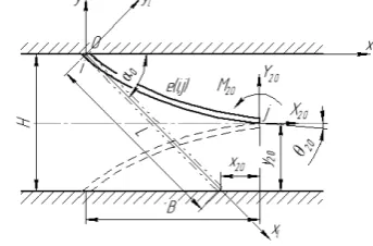
This paper considers the construction of dynamic sepa-ration elements, elastic elements of which are in the form of an inclined parabolic semi-cylinder [2] (Figure 1).
Figure 1 – Design scheme of the dynamic deflection element of the separation device
By virtue of the fact that fluviation changes the chan-nels form that causes the change of flow parameters, static and dynamic hydroaerostrances will occur [10], among which the greatest interest will be represented by flutter and buffeting associated with the oscillating mo-tion, when an essential role is played by elastic,
aerody-namic forces and inertia forces. As a result of the vibra-tion of the elastic deflecvibra-tion elements, there will also be oscillations of the gas-liquid flow, as a result of which the droplet may become concentrated in the liquid, and, con-sequently, the efficiency of the separation increases. Thus, due to the use of flutter or buffeting, the use of dynamic separation devices is possible. It should be noted that the acoustic coagulation of droplets is one of the traditional ways of improving separation efficiency. When applying acoustic oscillations with a certain fre-quency on the gas dispersion flow, intensive mechanical vibrations of highly dispersed suspended liquid droplets in the gas dispersion flow occur, resulting in a sharp in-crease in the number of their collisions. But the opposite effect of overlaying acoustic vibrations, in particular, the increase of the dispersion of the liquid phase, can be ob-served [11]. Therefore, it is necessary to know the specif-ic frequency of oscillations in whspecif-ich there is a coagula-tion of suspended particles in the liquid. For the case of fluctuations of the gas-liquid flow caused by the action of sound waves, developed calculation methods that are well-matched with experimental results [12, 13].
Considering the foregoing, as in the case of acoustic vibratory coagulation, in order to achieve a positive effect on the oscillations imposed on the flow, it is necessary to know the optimum frequency thereof, which depends on the dispersion of the liquid phase. Whereas, the value of the flutter frequency depends on the geometric and elastic characteristics of the baffle elements. As can be seen from Figure 1, the elastic elements of the channel are pre-deformed, which means that they generate stresses, which increases their rigidity and consequently increases the flow rate at which the flutter can occur.
Therefore, the purpose of this paper is to conduct a static calculation of dynamic deflection elements of sepa-ration devices to research the previous stressed state.
2
Results
The previous deformed state of the dynamic deflection element of the separation device is modelled using ana-lytical dependencies of the finite element method. In particular, the dynamic deflection element is represented by two-node finite element e (i, j) with six degrees of freedom [14]. The design scheme of the preliminary de-formed state of the dynamic deflection element of the separation device is shown in Fig. 2.
Journal of Engineering Sciences, Volume 4, Issue 2 (2017), pp. B 19–B 24 B 21
B
The local coordinate system xl - yl is associated withthe undeformed middle surface of the dynamic deflection element, the global coordinate system x - y - with the fixed body.
The model provides the use of the deflection function of a median surface in the form of the cubic polynomial, presented in a matrix form:
l 0l,l x U
y (1)
where {U}0l = {y10l, θ10l, y20, θ20l} T–
the column-vector of nodal displacement; {Ф} – row-vector of form orthog-onal functions (interpolation matrix):
; ; 2 3 ; 2 ; 2 3 1 3 3 2 2 2 3 3 2 2 2 3 3 2 2 1 3 3 2 2 1 L x L x L L x L x L x L x L x L L x L x l l l l l yl l l l l l l yl (2)
L – – plate length; y10l, y20l – nodes transverse dis-placement i, j; θ10l, θ20l– turn angles of cross-sections.
The index “0” indicates the consideration of the static equilibrium condition; the index “l” corresponds to the local coordinate system; indices “1”, “2” indicate the belonging of a physical quantity to nodes i, j, respective-ly.
The connection between displacements of the deflec-tion element and the forces that caused its deformadeflec-tion is determined by the matrix equation of the elastic equilib-rium:
C l
U 0l F 0l, (3)where {F}0l = {Y10l, M10l, Y20l, M20l}T– vector of sum-marized forces, the elements of which are transverse forces Y10l, Y20l, applied in the nodes i, j, and the corre-spondent moments M10l, M20l; [C]l– a local stiffness ma-trix whose elements are defined as second derivatives by the corresponding summarized displacements from the quadratic form of the plate deformation potential energy:
, 2 1 0 2 2 2 2 2, U dx
dx d U dx d EI U U C L l l T l l j l i l j i
l
(4)
where E– Young’s modulus; I = b3h/12 –– moment of cross section inertia for the rectangle cross section plate with height b and thickness h.
The last formula does not consider the energy of the longitudinal deformation of the dynamic deflection ele-ment due to its sufficient flexibility, and the local stiff-ness matrix takes on the following form:
. 4 6 2 6 6 12 6 12 2 6 4 6 6 12 6 12 2 2 2 2 3 L L L L L L L L L l L L l EI Cl (5)In the global coordinate system x - y matrix equation of elastic equilibrium has the form similar to the formula (3):
C U 0 F 0, (6)where {U}0 = {x10, y10, θ10, x20, y20, θ20}T– the column
vector of the nodal displacement {F}0 = {X10, Y10, M10,
X20, Y20, M20}T – vector of summarized nodal forces with
components along the axis x (X10, X20), y (Y10, Y20) and
moment (M10, M20); [C] – the global stiffness matrix.
The transition from the local to the global matrix of ri-gidity is carried out due to the next formula:
C T ClET , T (7)
where [T] – transformation matrix:
; 1 0 0 0 0 0 0 cos sin 0 0 0 0 sin cos 0 0 0 0 0 0 1 0 0 0 0 0 0 cos sin 0 0 0 0 sin cos 0 0 0 0 0 0 0 0
T (8)
[C]El– the local stiffness matrix (5), expanded to size 6×6 by inputting values that correspond to longitudinal deformation:
; 4 6 0 2 6 0 6 12 0 6 12 0 0 0 0 0 2 6 0 4 6 0 6 12 0 6 12 0 0 0 0 0 2 2 2 3 2 3 2 2 2 3 2 3 L EI L EI L EI L EI L EI L EI L EI L EI L EA L EA L EI L EI L EI L EI L EI L EI L EI L EI L EA L EAClE
(9)
A = b·h– plate cross-section area.
The case of a flexible deflection element allows not to consider in formula (9) the extension stiffness EA/L.
Taking account of the kinematic boundary conditions for the node i (x10 = y20 = 0; θ10 = 0) allows to expand the
equation (6) of the elastic equilibrium of the dynamic deflection element into two matrix equations - separately for the nodes i and j:
B 22 Investigation of Operating Processes in Machines and Devices
B
where the next descriptions are comprehended:
;
;
. ; 4 cos 6 sin 6 cos 6 cos 12 2 sin 6 sin 6 2 sin 6 sin 12 ; 2 cos 6 sin 6 cos 6 cos 12 2 sin 6 sin 6 2 sin 6 sin 12 20 20 20 0 20 20 20 0 10 10 10 0 2 0 0 0 0 2 0 0 0 0 2 3 2 0 0 0 0 2 0 0 0 0 2 3
y x U M Y X F M Y X F L L L L L L EI C L L L L L L EI C j j i j i (11)The first equation of formula (10) allows to determine the internal forces and the moment that become in fixing the deflection element in the body of the separation de-vice: , 2 cos 6 sin 6 cos 6 cos 12 2 sin 6 sin 6 2 sin 6 sin 12 10 10 10 2 0 0 0 0 2 0 0 0 0 2 3 10 10 10 y x L L L L L L EI M Y X (12)
or in expanded form:
3 sin 3 cos 2
.2 ; cos cos 2 2 sin 6 ; sin 2 sin sin 2 6 20 0 20 0 20 2 10 0 20 0 2 20 0 20 3 10 0 20 0 20 0 2 20 3 10 L y x L EI M L y x L EI Y L y x L EI X (13)
The second equation of formula (10) determines the internal forces that effect the free edge of deflection ele-ment as a result of its previous deformation (during the assemble).
Further on, the matrix [C]j is chosen as the main stiff-ness matrix of the system, and the second equation (10) – the equation that determines the deformed state of the dynamic deflection element:
, 4 cos 6 sin 6 cos 6 cos 12 2 sin 6 sin 6 2 sin 6 sin 12 20 20 20 2 0 0 0 0 2 0 0 0 0 2 3 20 20 20 y x L L L L L L EI M Y X (14)
or in expanded form:
3 sin 3 cos 4
.2 ; cos cos 2 2 sin 6 ; sin 2 sin sin 2 6 20 0 20 0 20 2 20 0 20 0 2 20 0 20 3 20 0 20 0 20 0 2 20 3 20 L y x L EI M L y x L EI Y L y x L EI X
(15)In the second equation (10) і and in the subsequent i n-dex “j” is not specified, and the index “20” is replaced by “0”.
The final equation of an elastic equilibrium that deter-mines the previous deformed state of a dynamic deflec-tion element is the equadeflec-tion (6) for the following formu-las of the global stiffness matrix [C] and the nodes dis-placement vectors {U}0 and of the generalized forces
{F}0 in accordance with formula (14):
;
. ; 4 cos 6 sin 6 cos 6 cos 12 2 sin 6 sin 6 2 sin 6 sin 12 20 20 20 0 20 20 20 0 2 0 0 0 0 2 0 0 0 0 2 3 M Y X F y x U L L L L L L EI C
(16)The components of displacement {U}0 are
geometri-cally determined by the following correspondences:
, ; 2 sin ; cos 0 20 0 20 0 20
tg B H arctg H L y L B x (17)where angle θ20 is determined approximatively for the
parabolic plate bending; width B for the deformed plate is in the range (Bmin, Bmax) the limiting values of which are
determined by the following correspondences:
. 4 ; 2 2 2 max min H L B H L B (18)
The least value Bmin corresponds to the condition of the
maximum possible deformation of the element, the larg-est value Bmax is the rotation of the straight position
ele-ment.
3
Discussion
The above-described static analysis mathematical model of the previously deformed dynamic deflection element of the separation device is reliable for the deflec-tion forms of the middle surface that is interpolated by a quadratic or cubic polynomial. The transition to a two-dimensional formulation is substantiated for the case of setting external forces as a result of pressure field inte-grating along the plate height.
Further on, there is going to be proposed the ways of updating the initial parameters of this model and identifi-cation of unknown parameters – model’s internal varia-bles – in accordance with available experimental data and the results of numerical simulation based on the use of both the regression analysis and artificial intelligence systems, particularly artificial neural networks.
Journal of Engineering Sciences, Volume 4, Issue 2 (2017), pp. B 19–B 24 B 23
B
─ the expansion of understanding of the theoreticalfoundations of separation processes of gas-dispersed systems in apparatuses with intensive hydrodynamic regimes;
─ analysis of implementation of the physical conditions and formation models of gas-dispersed systems; ─ analysis of mechanics and dynamics of the turbulent
gas-dispersed flows;
─ formulation of theoretical and practical problems of continuum mechanics and separation processes of the gas-dispersed flows;
─ definition of the main methods to increase energy efficiency and the separation value of the modular sep-aration devices.
4
Conclusions
The possibility of extending the dynamic separation elements application through the use of aero-hydroelastic effects, namely flutter, is revealed. For this purpose, a research of the static equilibrium condition of elastic deflection elements was conducted, because their pre-deformation has a sufficient effect on the flutter fre-quency. The stiffness of pre-deformed, their maximum and minimum possible deflections are determined.
Hereafter, it is planned to conduct research aimed at solving the stationary problem of aero-hydroelasticity of separation devices dynamic deflection elements. This problem can be solved in stationary and nonstationary formulations. Herewith, the analysis of the separation device deflection element deformation as the result of gas-liquid flow action should be based on the determining and further research of equation of plate flexural strain
relative to the predetermined in this article static strained condition in accordance with the calculation scheme giv-en in the Figure 2.
It is also necessary to analyze the dynamics of the sep-aration device deflection element with respect to the posi-tion of the static equilibrium condiposi-tion defined above, as well as plates dynamic equilibrium, including the deter-mination of the optimal geometric dimensions that will provide the oscillation frequency of the element, which will coagulate the liquid droplets as a result of collision with the deflection elements of separation device.
5
Acknowledgements
Close cooperation between the Processes and Equip-ment of Chemical and Petroleum-Refineries DepartEquip-ment and the Department of General Mechanics and Machine Dynamics allows carrying out the static calculation of the dynamic deflection elements for separation devices as a result of interdisciplinary research in chemical and petro-leum industry within the following research commis-sioned by the Ministry of Education and Science of Ukraine: “Development and implementation of energy efficient modular separation devices for oil and gas puri-fication equipment” (No. 0117U003931) [15].
This research project is aimed at im-proving the tech-nology of inertia-filtering separation of two-phase flows, modelling of dynamic processes of separation of hetero-geneous systems with the analysis of the vibration influ-ence (acoustic oscillations) and combined heat and mass transfer, the development and implementation of energy-efficient modular separation devices.
References
1. Liaposhchenko, O. O., Sklabinskyi, V. I., Zavialov, V. L., Pavlenko, I. V., Nastenko, O. V., & Demianenko, M. M. (2017). Ap-pliance of Inertial Gas-Dynamic Separation of Gas-Dispersion Flows in the Curvilinear Convergent-Divergent Channels for Compressor Equipment Reliability Improvement. IOP Conference Series: Materials Science and Engineering, Vol. 233. DOI: https://doi.org/10.1088/1757-899X/233/1/012025.
2. Liaposhchenko, O. O., Pavlenko, I. V., Nastenko, M. M., Usyk, R. Yu., & Demianenko, M. M. (2015). Sposib vlovlyuvannya vysokodyspersnoyi kraplynnoyi ridyny z hazoridynnoho potoku [The method of capturing highly dispersed dropped liquid from the gas-liquid flow]. Certificate of the authorship, Ukraine, No. 102445 U, B01D 45/04 (2006.01). Sumy, Sumy State Universi-ty, No. u201505124, bulletin No. 20 [in Ukrainian].
3. Liaposhchenko, O. O., Nastenko, M. M., Pavlenko, I. V., et al. (2016). Sposib vlovlyuvannya vysokodyspersnoyi kraplynnoyi ridyny z hazoridynnoho potoku [The method of capturing highly dispersed dropped liquid from the gas-liquid flow]. Certificate of the authorship, Ukraine, No. 111039 U, B01D 45/00 (2006.01). Sumy, Sumy State University, No. u201605061, bulletin No. 20 [in Ukrainian].
4. Sloboda, O., Korba, P., Hovanec, M., & Pila, J. (2016). Numerical approach in aeroelasticity. Scientific Journal of Silesian Uni-versity of Technology. Series Transport, Vol. 93, 115–122. DOI: https://doi.org/10.20858/sjsutst.2016.93.12.
5. Afanasyeva, I. N., & Lantsova I. Yu. (2017). Numerical simulation of an elastic structure behavior under transient fluid flow ex-citation. Investigation of aerodynamic instability of a thin plate. MATEC Web of Conferences, Vol. 117, article No. 00099. 6. Zahed, P., Zhang, J.; Arabnejad, H., McLaury, B. S., & Shirazi, S. A. (2017). CFD simulation of multiphase flows and erosion
predictions under annular flow and low liquid loading conditions. WEAR, Issue 376, 1260–1270. DOI: https://doi.org/10.1016/j.wear.2017.01.111.
B 24 Investigation of Operating Processes in Machines and Devices
B
8. Liaposhchenko, О., Nastenko, O., Pavlenko, I. (2017). The model of crossed movement and gas-liquid flow interaction with captured liquid film in the inertial-filtering separation channels. Separation and Purification Technology, Vol. 173, 240–243. DOI: 10.1016/j.seppur.2016.08.042
9. Nastenko, O., Liaposhchenko, O., et al. (2016). Mathematical modelling of separation process by coupled heat transfer in the in-ertial-filtering gas separator-condenser. Inżynieria i Aparatura Chemiczna, No. 2, 62–63.
10. Karintsev, I. B., & Pavlenko, I. V. (2017). Hydroaeroelasticity: a textbook. Sumy, Sumy State University.
11. Brittle, S., Desai, P., Ng, W. C., Dunbar, A., Howell, R., Tesar, & Zimmerman, W. B. (2015). Minimising microbubble size through oscillation frequency control. Chemical engineering research & design, Issue 104, 357–366. DOI: https://doi.org/10.1016/j.cherd.2015.08.002.
12. Wu, Y. R., & Wang, C. H. (2017). Theoretical analysis of interaction between a particle and an oscillating bubble driven by ul-trasound waves in liquid. Chinese physics B, Volume 11, Issue 26, No. 114303. DOI: https://doi.org/10.1088/1674-1056/26/11/114303.
13. Go, D. B., Atashbar, M. Z., Ramshani, Z., & Chang, H. C. (2017). Surface acoustic wave devices for chemical sensing and mi-crofluidics: a review and perspective. Analytical methods, Volume 28, Issue 9, 4112–4134. DOI: https://doi.org/10.1039/c7ay00690j.
14. Pavlenko, I. V. (2006). Finite element method for the problems of strength of materials and linear theory of elasticity. Sumy : Sumy State University [in Russian].