Infogain Publication (Infogainpublication.com) ISSN: 2454-1311
Design and Manufacturing of Press Tools for
Compressor Shell
V.Mallikarjuna
1, Dr. B.James Prasad
2, S.Md Jameel Basha
3, K.Rajesh
41Assistant Professor, Department of Mechanical, AITS, JNTUA University, India. 2Professor, Department of Mechanical, K.L. University, Guntur, Andhra Pradesh, India.
3Assistant Professor, Department of Mechanical, AITS , JNTUA University, India.
4Assistant Professor, Department of Mechanical, Mallareddy Engineering college, India.
Abstract— The role of Sheet Metal has become very
prominent with the use of Press Tools. It is one of the fundamental forms used in metalworking, and can be cut and bent into a variety of different shapes. Countless everyday objects are constructed of the material. Thicknesses can vary significantly, although extremely thin thicknesses are considered foil or leaf, and pieces thicker than 6 mm (0.25 in) are considered plate.The project deals with Compressor Shell Lower Housing. The Compressor Shell holds all the parts of the compressor in pre-defined location for the compressor to fool proof. The component should be freed from burrs and also to dimensional accurate. The outcome component is been inspected in the Quality department so as to check the Dimensional accuracy is been achieved.
Keywords— Compressor shell, Lower Housing Shell, Thick Hot Rolled Strip.
I. INTRODUCTION
In today’s practical and cost conscious world, sheet metal parts have already replaced many expensive cast, forged and machined products. The reason is obviously the relative cheapness of stamped, mass produced parts as well as greater control of their technical and aesthetic parameters. That the world slowly turned away from heavy, ornate and complicated shapes and replaced them with functional, simple and logical forms only enhanced this tendency towards sheet metal products. The common sheet metal forming products are metal desks, file cabinets, appliances, car bodies, aircraft fuselages, mechanical toys and beverage cans. Sheet forming dates back to 5000 B.C., when household utensils and jewelry were made by hammering and stamping gold, silver and copper. Due to its low cost and generally good strength and formability characteristics, low carbon steel is the most commonly used sheet metal. For aircraft and aerospace applications, the common sheet materials are aluminum and titanium
II. DESIGN PROCEDURES
COMPONENT NAME: Lower Housing Shell MATERIAL: Thick Hot Rolled Strip
THICKNESS: 2.67 / 2.97 mm. 2.1. BLANKING:
This operation is the first and foremost operation in the manufacturing procedure. The blank diameter is been calculated by considering the blank development procedure from Die Design Handbook.
2.2.BLANK DIAMETER:
Fig.1:Blank Development for irregular shells.
R₁= d − R + R d − R + 2R
+2d h − R
R₂= c − R + R c − R + 2R
+2c h − R
c = 208.22, d = 145.94, Rs= 16.12, h = 152.73
R₁= 145.94 − 16.12+2 16.12 + 2 145.94 152.50 − 16.12+ 16.12 145.94 − 16.12
= 16853.2324 + 2092.6984 + 519.7088
+39806.5944 =√59339.3664
= 243.45 mm.
Infogain Publication (Infogainpublication.com) ISSN: 2454-1311
= 36902.41 + 3096.652 + 519.7088
+56794.0872 = √97408.6392
= 312.103 mm.
Blank Diameter = Major axis + 2 (R2 – c)
= 214.88 + 2(103.883) = 422.646 ≈ ∅420 mm.
Strip Layout: Strip size:
If n = No. of Blanks.
Strip Length: [from Basic Die Making (BDM) Pg- 181]
L= n×D + (n+1) G. = (10 × 420) + (10 + 1) G = 4200 + (11 × 5.94) = 4200 + 65.34 = 4265.24 mm.
Table.1 : Stock Thickness
ONE-PASS SINGEL STATION DIES
T= STOCK THICKNESS
D (INCHES)
G OR
H
SMALLEST G OR H (INCHES)
TO 1 ¾ T 1/32
1-3 T 3/64
3-6 1 ¼ T 3/32
6-10 1 ¼ T 1/8
10-15 1 ½ T 1/8
Where,
D= Blank Diameter. G= Bridge Scrap. = 2T.
= 2×2.97 = 5.94 mm. T= Thickness of the Stock.
Strip Width:
Ws= D+2H.
= 420 + 2 × 5.94
= 431.88 mm. ≈ 428.9 mm. Where,
D = Blank Diameter. H = Front Scrap = T
Weight of Raw Material:
Wr = L×Ws×t×ρ× 10
= 4265.34 × 428.9 × 2.97 × 7.85 × 10ˉ⁶
= 42651647.3 × 10ˉ⁶
= 42.65 kg. Where,
L= Length of the strip.
Ws= Width of the strip
t = Thickness of the component. ρ = Density.
= 7.85× 10 kg/mm" (for Steel)
Net Weight of Component:
Wc = A×t×ρ× 10
= 3.14 × (210)2 × 2.97 × 7.85 × 10-6 = 3228452.07 × 10-6
= 3.228 kg. Where,
A = Area of Blank. = π
#d mm
t = Thickness of the component.
ρ = Density.
= 7.85× 10 kg/mm" (for Steel)
Percentage of Utilization:
%U = $%×&
$' × 100
= (3.228 × 10) / (42.65) × 100 = 75.6%
Where,
Wc = Weight of the component.
Wr= Weight of the Raw material.
n = No. of Blanks
Fig.2: Strip Layout.
Component Name
AW Lower Housing of Compressor Shell
Material Thick H.R.S
Strip Size 4265.24 x 428.9 mm.
No. of Blanks 10
Weight of Raw Material
42.65 kgs.
Net Weight of the Blank
3.228 kgs.
Percentage of Utilization
Infogain Publication (Infogainpublication.com) ISSN: 2454-1311 Perimeter:
P = 2πr (For Circular Blank) = 2 ×π× 210
= 1318.8 mm. Where,
r = Radius of Blank
Tonnage: [from Tool Parameters Pg – 07]
Shear Force = Fsh =+×,×-×.1222/0
= 1." × 1"13.3 × .45 ×"
1222
= 183.307 tons
≈ 500 tons (this value is considered according press availability) Where,
Fsh = Shear force in tons.
k= Factor of Safety (1.3 – 1.5) l = Length of the Periphery. t = Thickness of the component. Ssh = Shear strength
= 36 kg mm2
9 (for Steel)
Clearance:
• Recommended clearance can be calculated by:: = ; × <
Where,
c = clearance.
a = allowance. t = stock thickness.
• Allowance ‘a’ is determined according to type of metal:
Table 2: Metal group.
Metal group a
1100S and 5052S aluminum alloys, all
tempers 0.045
2024ST and 6061ST aluminum alloys; brass, soft cold rolled steel, soft stainless
steel.
0.060
Cold rolled steel, half hard; stainless steel,
half hard and full hard. 0.075
Fig.3 Clearance.
Db determines blank size
Dh determines hole size
• Distance between the punch and die
• Typical values range between 4% and 8% of stock thickness
• If too small, fracture lines pass each other, causing double burnishing and larger force
• If too large, metal is pinched between cutting edges and excessive burr results
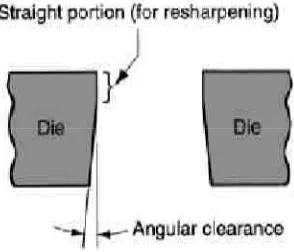
III. ANGULAR CLEARANCE
It is the enlarged section below the die opening that allows the blank to fall from the die. Its purpose is to allow slug or blank to drop through die.
Fig.4: Angular Clearance
Typical values: 0.25° to 1.5° on each side
3.1 Design of Blanking tool:
Theoretical Valves:
Thickness of Die plate (td) = A=>?@
Infogain Publication (Infogainpublication.com) ISSN: 2454-1311
Thickness of Punch Holder (th) = 0.5 × <B
= 29.25 mm. Thickness of Top Bolster (tt) = 1.25 × <B
= 73.125 mm Thickness of Stripper plate (ts) =0.5 × <B.
= 29.25mm.
Thickness of Bottom Bolster (tb) = 1.75 × <B = 102.37 mm.
3.2 Practical Valves:
Thickness of Die plate (td) = 19 mm.
Thickness of Punch Holder (th) = 30 mm.
Thickness of Top Bolster (tt) = 60 mm.
Thickness of Stripper plate (ts) = 13 mm.
Thickness of Bottom Bolster (tb) = 70 mm.
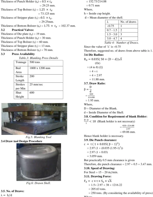
3.3 Press Availability
Table.3: Blanking Press Details
Tonnage 500 tons
Bed Area
1800 x 1200 mm
Stroke Length
200
Strokes per Min
25 mm/sec
Shut Height
600
Fig.5: Blanking Tool
3.4 Draw tool Design Procedure
Fig.6: Drawn Shell.
3.5. No. of Draws: λ= h d⁄
= 152.73/214.88 = 0.71 mm Where,
h = Inside cup height.
d = Mean diameter of the shell.
λ No. of draws
<0.75 1 0.7 - 1.5 2 1.5 - 3.0 3 3.0 - 4.7 4
Table 4: Number of Draws.
Since the value of ‘λ’ is <0.75
Therefore, suggested no. of draws from above table is 1.
3.6 Die Radius:
RD= 0.035 50 + D − d √t
(Or) = (4 to 8) t = 4 × t = 4 × 2.97 = 11.88 mm.
3.7. Draw Ratio:
β=D
d = # 2
1#.33
= 1.95 mm. Where,
D = Diameter of the Blank. d = Inside Diameter of the Shell.
3.8. Condition for Requirement of blank Holder: F D
- < 18 (Blank holder is not necessary)
= # 2 1#.33
.45
= 69.06 mm. Hence blank holder is necessary.
3.9. Die Punch clearance:
c = t 1 + 0.035 β− 1 "
= 2.97 (1 + (0.035 (1.95-1)3)) = 2.97 (1 + 0.03)
= 3.059 mm.
But practically 0.5 mm clearance is given
Therefore, die punch clearance = 2.97 + 0.5 = 3.47 mm.
3.10. Speed of Drawing:
For Steel = 15 – 20 m/min.
3.11. Drawing Force:
FD = c × t × SM× √A
= 1.5× 2.97 × 38 × 1216.22 = 205.63 tons.
Infogain Publication (Infogainpublication.com) ISSN: 2454-1311
c = 0.5 to 2.0
A = Forming Area (or) Deformed Area.
SM = Ultimate Tensile Strength in kg mm⁄ . = 38 kg mm⁄ for Steel.
3.12. Theoretical Valves:
Thickness of Die plate (td) = =>A B
= A√250= 62.9 mm. Thickness of Top Bolster (tt) = 1.25 × <B
= 78.625 mm. Thickness of Bottom Bolster (tb) = 1.75 × <B
= 110.075 mm.
3.13. Practical Valves:
Thickness of Die plate (td) = 54 mm.
Thickness of Top Bolster (tt) = 60 mm.
Thickness of Bottom Bolster (tb) = 70 mm.
Thickness of Blank Holder = 50 mm. Thickness of shedder = 50 mm.
Thickness of shedder back plate = 10 mm
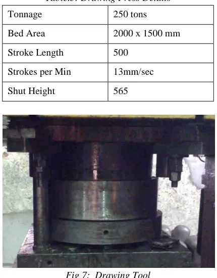
3.14. Press Availability:
Table.5: Drawing Press Details
Tonnage 250 tons
Bed Area 2000 x 1500 mm
Stroke Length 500
Strokes per Min 13mm/sec
Shut Height 565
Fig 7: Drawing Tool
Shell trimming tool design :
Fig 8: Trimmed shell.
3.15. Shearing Force :
Shearing force, Fsh =+×,×-×.1222/0
= 1." × 1 4.2 × .45 × "
1222
= 17.939
≈ 100 tons (according to press availability).
Where,
Fsh = Shear force in tons.
k= Factor of Safety (1.3 – 1.5) l = Length of the Periphery.
t = Thickness of the component. Ssh = Shear strength.
= 36 kg mm2
9 (for Steel).
3.16. Theoretical Valves:
Thickness of Die plate (td) = A=>B
= A√100= 46.4 mm. Thickness of Top Bolster (tt) = 1.25 × <B
= 58 mm.
Thickness of Bottom Bolster (tb) = 1.75 × <B
= 81.2 mm.
3.17. Practical Valves:
Thickness of Die plate (td) = 42 mm.
Thickness of Top Bolster (tt) = 60 mm.
Thickness of Bottom Bolster (tb) = 70 mm.
Thickness of Locator = 20 mm
3.18. Press Availability:
Table 6:Trimming Press Details.
Tonnage 100 tons
Bed Area 750 x 560 mm
Stroke Length 600
Strokes per Min 22 mm/sec
Infogain Publication (Infogainpublication.com) ISSN: 2454-1311
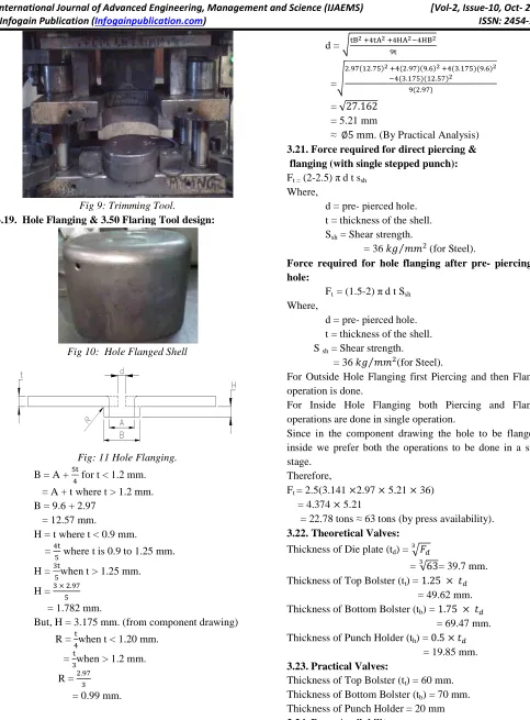
Fig 9: Trimming Tool.
3.19. Hole Flanging & 3.50 Flaring Tool design:
Fig 10: Hole Flanged Shell
Fig: 11 Hole Flanging.
B = A +
P-# for t < 1.2 mm.
= A + t where t > 1.2 mm. B = 9.6 + 2.97
= 12.57 mm.
H = t where t < 0.9 mm.
= #-P where t is 0.9 to 1.25 mm.
H =
"-Pwhen t > 1.25 mm.
H = " × .45
P
= 1.782 mm.
But, H = 3.175 mm. (from component drawing)
R = #-when t < 1.20 mm.
=
-"when > 1.2 mm.
R = .45
"
= 0.99 mm.
3.20. Pre- Pierced Hole Size (d):
d = -QR S#-TR S#UT4- R #UQR
=
.45 1 .5PR S# .45 4. R S# ".15P 4. R # ".15P 1 .P5R
4 .45
= √27.162 = 5.21 mm
≈ ∅5 mm. (By Practical Analysis)
3.21. Force required for direct piercing & flanging (with single stepped punch):
Ft = (2-2.5) πd t ssh
Where,
d = pre- pierced hole. t = thickness of the shell. Ssh = Shear strength.
= 36 VW XX⁄ (for Steel).
Force required for hole flanging after pre- piercing the hole:
Ft = (1.5-2) πd t Ssh
Where,
d = pre- pierced hole. t = thickness of the shell. S sh = Shear strength.
= 36 VW XX⁄ (for Steel).
For Outside Hole Flanging first Piercing and then Flanging operation is done.
For Inside Hole Flanging both Piercing and Flanging operations are done in single operation.
Since in the component drawing the hole to be flanged is inside we prefer both the operations to be done in a single stage.
Therefore,
Ft = 2.5(3.141 ×2.97 × 5.21 × 36)
= 4.374 × 5.21
= 22.78 tons ≈ 63 tons (by press availability).
3.22. Theoretical Valves:
Thickness of Die plate (td) = A=>B
= A√63= 39.7 mm. Thickness of Top Bolster (tt) = 1.25 × <B
= 49.62 mm. Thickness of Bottom Bolster (tb) = 1.75 × <B
= 69.47 mm. Thickness of Punch Holder (th) = 0.5 × <B
= 19.85 mm.
3.23. Practical Valves:
Thickness of Top Bolster (tt) = 60 mm.
Thickness of Bottom Bolster (tb) = 70 mm.
Thickness of Punch Holder = 20 mm
Infogain Publication (Infogainpublication.com) ISSN: 2454-1311
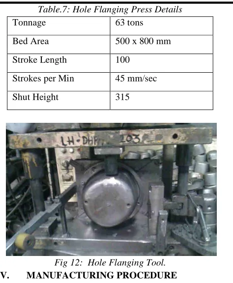
Table.7: Hole Flanging Press Details
Tonnage 63 tons
Bed Area 500 x 800 mm
Stroke Length 100
Strokes per Min 45 mm/sec
Shut Height 315
Fig 12: Hole Flanging Tool.
IV. MANUFACTURING PROCEDURE
Manufacturing of the tools involved the different machinning operations which is given below .
• Turnning
• Milling
• Grinding
• Boring
• Drilling
• Tapping
4.1 Manufacturing procedure of Blanking tool.
S.NO : 01
DESCRIPTION : TOP BOLSTER & BOTTOM PLATE. MATERIAL : MILD STEEL
RAW MATERIAL SIZE : 75x760x910mm
4.1.1. Procedure:
1. Mill right angle at one side & maintain length and width on Horizontal milling machine.
2. Rough Milling top and bottom faces of plate on vertical milling m/c.
3. Reference grinding at one side on surface grinding m/c.
4. Grinding on top and bottom surfaces on surface grinding m/c.
5. Centre drill for all holes on CNC Milling machine. 6. Boring of all holes i.e. pillar, pillar bushes, seating
holes & fixed holes on jig boring m/c.
7. Drill and C’ bore & tapping to suit die housing by using taps, drills & reamers.
8. Inspection report of plate.
9. Assembly.
S.NO : 02
DESCRIPTION : PUNCH & DIE HOLDER. MATERIAL : MILD STEEL.
RAW MATERIAL SIZE : Ø660 x 115
1. Rough turnning on lathe m/c. 2. Thickness milling on milling m/c.
3. Thickness grinding on surface grinding m/c.
4. Boring on CNC milling m/c.
5. Pocket milling on milling m/c. 6. Centre drill on CNC milling m/c.
7. Drill and C’ bore & tapping to suit bottom bolster by using taps, drills & reamers.
8. Inspection report of plate.
9. assembly.
S.NO : 03
DESCRIPTION : PUNCH & DIE INSERTS.
MATERIAL : HIGH CARBON HIGH CHROMIUM STEEL.
RAW MATERIAL SIZE : 315 x 70 x 55 PROCEDURE:
1. Mill right angle at one side & maintain length and width on horizontal milling machine.
2. Rough milling top and bottom faces of plate on vertical milling m/c.
3. Reference grinding at one side on surface grinding m/c.
4. Grinding on top and bottom surfaces on surface grinding m/c.
5. Centre drill for all holes on CNC Milling machine. 6. Angular milling, radius milling on CNC Milling
m/c.
7. Angular grinding on surface grinding m/c.
8. Drill and C’ bore & tapping to suit die holder by using taps, drills & reamers.
9. Inspection report of plate. 10. Heat treatment.
11. Finish sizes by using CNC Milling and surface grinding.
12. Inspection report before assembly.
Infogain Publication (Infogainpublication.com) ISSN: 2454-1311
S.NO : 04
DESCRIPTION : GUIDE PILLARS. MATERIAL : EN31.
RAW MATERIAL SIZE : Ø70 x 355 PROCEDURE:
1. Rough turning on lathe m/c. 2. Heat treatment.
3. Grinding on cylindrical grinding m/c. 4. Inspection report of plate.
5. Assembly.
S.NO : 05
DESCRIPTION : GUIDE BUSHES. MATERIAL : EN31.
RAW MATERIAL SIZE : Ø90 x 160. PROCEDURE:
1. Rough turning & drilling on lathe m/c. 2. Heat treatment.
3. ID and OD grinding on cylindrical grinding m/c. 4. Inspection report.
5. Assembly.
ASSEMBLING:
1. Fix guide pillars in bottom plate & guide bushel in top plate for die set assembly.
2. Fix die inserts in die holder & fixed it into bottom plate.
3. Fix punch inserts in punch holder & fixed it into top plate.
4. Check alignment of punch and die.
5. Tool inspection report. 6. Tool trail report.
7. Tool ready for production.
4.2. Manufacturing procedure of drawing tool:
S.NO : 01
DESCRIPTION : TOP BOLSTER & BOTTOM PLATE. MATERIAL : MILD STEEL.
RAW MATERIAL SIZE : 75x760x910mm PROCEDURE:
1. Mill right angle at one side & maintain length and width on horizontal milling machine.
2. Rough milling top and bottom faces of plate on vertical milling m/c.
3. Reference grinding at one side on surface grinding m/c.
4. Grinding on top and bottom surfaces on surface grinding m/c.
5. Centre drill for all holes on CNC Milling machine.
6. Boring of all holes i.e. Pillar, pillar bushes, seating holes & fixed holes on jig boring m/c.
7. Drill and C’bore & tapping to suit die housing by using taps, drills & reamers.
8. Inspection report of plate.
9. Assembly.
S.NO : 02
DESCRIPTION : DIE HOUSING PLATES (TOP, MIDDLE & BOTTOM).
MATERIAL : MILD STEEL.
RAW MATERIAL SIZE : [DIE HOUSING TOP: Ø400x100, DIE HOUSING MIDDLE: Ø400x75 & DIE HOUSING Ø400x95]
PROCEDURE:
1. Maintain OD on lathe machine.
2. All holes and ID boring on jig boring machine. 3. Elliptical profile wire cut on CNC wire cut machine. 4. Step milling (maintain deep as noted in drg ‘s) on
CNC vertical milling m/c.
5. Drill and C’bore & tapping to suit die housing by using taps, drills & reamers.
6. Inspection report of plate/bar.
7. Assembly.
S.NO : 03
DESCRIPTION :SHEDDER (Ø220 x 80). MATERIAL : EN-31.
RAW MATERIAL SIZE : Ø220 x 80 PROCEDURE:
1. Maintain OD on lathe machine.
2. Rough milling top and bottom faces of plate on vertical milling m/c.
3. All holes and ID boring on jig boring machine. 4. Elliptical profile wire cut on CNC wire cut machine. 5. Step milling (maintain deep as noted in drg ‘s) on
CNC vertical milling m/c.
6. Drill and C’bore & tapping to suit die housing by using taps, drills & reamers.
7. Heat treatment.
8. Surface grinding and maintain height on surface grinding m/c.
9. Inspection report of plate/bar.
10. Assembly.
ASSEMBLING:
Infogain Publication (Infogainpublication.com) ISSN: 2454-1311
2. Fix die inserts in die holder & fixed it into bottom plate.
3. Fix punch inserts in punch holder & fixed it into top plate.
4. Check alignment of punch and die.
5. Tool inspection report. 6. Tool trail report.
7. Tool ready for production.
4.3. Manufacturing procedure of shell trimming tools
S NO: 01
DESCRIPTION :TOP PLATE (Ø220 x 80). MATERIAL : EN-31.
RAW MATERIAL SIZE : Ø220 x 80 PROCEDURE:
1. Maintain OD on lathe machine.
2. Rough milling top and bottom faces of plate on vertical milling m/c.
3. All holes and ID boring on jig boring machine. 4. Elliptical profile wire cut on CNC wire cut machine. 5. Step milling (maintain deep as noted in drg ‘s) on
CNC vertical milling m/c.
6. Drill and C’bore & tapping to suit die housing by using taps, drills & reamers.
7. Heat treatment.
8. Surface grinding and maintain height on surface grinding m/c.
Inspection report of plate/bar. S NO: 02
DESCRIPTION : SPACER (Ø155 x 120). MATERIAL : EN-31.
RAW MATERIAL SIZE : Ø220 x 80 PROCEDURE:
1. Maintain OD on lathe machine.
2. Rough milling top and bottom faces of plate on vertical milling m/c.
3. All holes and ID boring on jig boring machine. 4. Elliptical profile wire cut on CNC wire cut machine. 5. Step milling (maintain deep as noted in drg ‘s) on
CNC vertical milling m/c.
6. Drill and C’bore & tapping to suit die housing by using taps, drills & reamers.
7. Heat treatment.
8. Surface grinding and maintain height on surface grinding m/c.
Inspection report of plate/bar. S NO: 03
DESCRIPTION : CUTTER (Ø220 x 80). MATERIAL : D2.
RAW MATERIAL SIZE : Ø225 x 20 PROCEDURE:
1. Maintain OD on lathe machine.
2. Rough milling top and bottom faces of plate on vertical milling m/c.
3. All holes and ID boring on jig boring machine. 4. Elliptical profile wire cut on CNC wire cut machine. 5. Step milling (maintain deep as noted in drg ‘s) on
CNC vertical milling m/c.
6. Drill and C’bore & tapping to suit die housing by using taps, drills & reamers.
7. Heat treatment.
8. Surface grinding and maintain height on surface grinding m/c.
Inspection report of plate/bar. S NO: 04
DESCRIPTION :PROFILE GUIDE FOLLOWER (Ø220 x 80).
MATERIAL : EN-31.
RAW MATERIAL SIZE : Ø225 x 145 PROCEDURE:
1. Maintain OD on lathe machine.
2. Rough milling top and bottom faces of plate on vertical milling m/c.
3. All holes and ID boring on jig boring machine. 4. Elliptical profile wire cut on CNC wire cut machine. 5. Step milling (maintain deep as noted in drg ‘s) on
CNC vertical milling m/c.
6. Drill and C’bore & tapping to suit die housing by using taps, drills & reamers.
7. Heat treatment.
8. Surface grinding and maintain height on surface grinding m/c.
Inspection report of plate/bar.
4.4. Manufacturing procedure of Piercing & Flaring tools
S.NO : 01 & 02
DESCRIPTION : TOP BOLSTER & BOTTOM PLATE. MATERIAL : MILD STEEL.
PROCEDURE:
1. Mill right angle at one side & maintain length and width on horizontal milling machine.
2. Rough milling top and bottom faces of plate on vertical milling m/c.
3. Reference grinding at one side on surface grinding m/c.
4. Grinding on top and bottom surfaces on surface grinding m/c.
Infogain Publication (Infogainpublication.com) ISSN: 2454-1311
6. Boring of all holes i.e. Pillar, pillar bushes, seating holes & fixed holes on jig boring m/c.
7. Drill and C’bore & tapping to suit die housing by using taps, drills & reamers.
8. Inspection report of plate.
9. Assembly.
S.NO : 03 & 04
DESCRIPTION : PUNCH HOLDER & DIE HOLDER MATERIAL : MILD STEEL
1. Rough turnning on lathe m/c. 2. Thickness milling on milling m/c.
3. Thickness grinding on surface grinding m/c.
4. Boring on CNC milling m/c.
5. Pocket milling on milling m/c. 6. Centre drill on CNC milling m/c.
7. Drill and C’ bore & tapping to suit bottom bolster by using taps, drills & reamers.
8. Inspection report of plate.
9. assembly.
S.NO : 07
DESCRIPTION : GUIDE PILLARS. MATERIAL : EN31.
PROCEDURE:
1. Rough turning on lathe m/c. 2. Heat treatment.
3. Grinding on cylindrical grinding m/c. 4. Inspection report of plate.
5. Assembly. S.NO : 08
DESCRIPTION : GUIDE BUSHES. MATERIAL : EN31.
PROCEDURE:
1. Rough turning & drilling on lathe m/c.
2. Heat treatment.
3. ID and OD grinding on cylindrical grinding m/c. 4. Inspection report.
5. Assembly. S.NO : 09 & 10
DESCRIPTION : PUNCH & DIE.
MATERIAL : HIGH CARBON HIGH CHROMIUM STEEL.
PROCEDURE:
1. Mill right angle at one side & maintain length and width on horizontal milling machine.
2. Rough milling top and bottom faces of plate on vertical milling m/c.
3. Reference grinding at one side on surface grinding m/c.
4. Grinding on top and bottom surfaces on surface grinding m/c.
5. Centre drill for all holes on CNC Milling machine. 6. Angular milling, radius milling on CNC Milling
m/c.
7. Angular grinding on surface grinding m/c.
8. Drill and C’ bore & tapping to suit die holder by using taps, drills & reamers.
9. Inspection report of plate. 10. Heat treatment.
11. Finish sizes by using CNC Milling and surface grinding.
12. Inspection report before assembly.
13. Assembly
V. PROCESS PLANNING SHEET
Part No.: AWX – 1678 – 05 Core Team: Control Plan Page No.:1 of 1
Part Name/ Description: Lower Housing -2.83 Thick.
Part/ Proces s No.
Process Name/ Operation
Machine
Characteristics Methods
No. Product
Product Specific./ Tolerance
Evaluation
Sample
Size Freq
.
01 Blanking 500T
1 Thickness 2.83+/-
0.10
Micrometer 2
sheets palle
t
2 Diameter 420+/-1.0 Tape 2
sheets palle
t
3 Appearan
ce
Free from Matrl.
Visual 100% Cont
Infogain Publication (Infogainpublication.com) ISSN: 2454-1311
Defects
02 Drawing 200T/250
T
1 Total
Height
179mm. Height Gauge 2 nos. 2
hrs.
2 Major
Axis
214.38-214.88
Profile Gauge 2 nos. 4
hrs.
3 Minor
Axis
186.18-186.68
Profile Gauge 2 nos. 4
hrs.
4 Appearan
ce
Free from weak zones
Visual 100% Cont
.
03 Trimming 100T
1 Total
Height
160mm. Height Gauge 2 nos. 2
hrs.
2 Appearan
ce
Free from steps &
dents
Visual 100% Cont
.
04 Hole
Flanging
100T
1 D.c Hole
Location
60 deg.+/- 1.0 deg.
Receiver Gauge
2 nos. 2
hrs.
2 D.c Hole
Dia.
8.03-8.13 Plug Gauge 2 nos. 2
hrs.
3 D.c Hole
Height
125.43+/- 1.60
Receiver Gauge
2 nos. 2
hrs.
4 Appearan
ce Free from burr, cracks, bend & dents.
Visual 100% Cont
.
05
Final
Inspection Manual
1 Major
Axis
214.38-214.88
Profile Gauge 100% Cont
.
2 Minor
Axis
186.18-186.68
Profile Gauge 100% Cont
.
3 Total
Height 156.85-157.5 Height Checking Gauge
100% Cont
.
4 Height at
Sides 152.08-152.73 Height Checking Gauge
100% Cont
.
5 D.c Hole
Dia.
8.03-8.13 Plug Gauge 100% Cont
.
6 D.c Hole
Location
60 deg.+/- 1.0 deg.
Receiver Gauge
100% Cont
.
7 Condition Free from
rust, burr.
Visual 100% Cont
.
VI. CONCLUSION
During the course of the project, a systematic approach has been followed in the design and development of all 5 tools. The design and development has been successfully
Infogain Publication (Infogainpublication.com) ISSN: 2454-1311
progress. At the manufacturing of tools having slit changes occurred while producing the shell.
REFERENCES
[1] Tool design data book [2] Design data book