2nd International Conference on Current Research Trends in Engineering and Technology © 2018 IJSRSET | Volume 4 | Issue 5 | Print ISSN: 2395-1990 | Online ISSN : 2394-4099 Themed Section: Engineering and Technology
Effect of Soil Structure Interaction on Steel Moment Resisting Frame
Designed By Performance Based Plastic Design Method
Surti Devanshi A., Dalal Sejal P.
Department of Civil Engineering, Sardar Vallabhbhai Patel Institute of Technology, Vasad, Anand, India
ABSTRACT
This paper presents study of seismic design considerations and design methodologies for steel moment resisting frame by performance based plastic design method with consideration of soil structure interaction. Performance-Based Plastic Design (PBPD) method has been recently evolved from the Performance based seismic design (PBSD) to achieve enhanced performance of earthquake resistant structures considering the participation of inelastic state of the material. The concept of design is mainly based on pre-selected target drift and yield mechanism as performance criteria. Performance Based Plastic design depends on “strong column-weak beam” theory, in which the pattern of failure is pre-determined. The various parameters of soil structure when included in PBPD method gives better approach towards the method. A brief study on effects of soil structure interaction on steel moment resisting frame is presented in this paper.
Keywords: Pre-selected target drift, Yield mechanism, Strong column-weak beam concept, steel moment resisting frame, PBPD, soil structure interaction
I. INTRODUCTION
It is well recognised that structures designed by current codes as expected to undergo large inelastic deformations during major earthquakes. However, seismic design approach is generally built on based on elastic structural behaviour and accounts for the inelastic behaviour in a somewhat implicit and indirect manner.
To solve the problem of undesirable and unpredictable responses of a structure to get more predictable structural performances a complete new methodology in which no need of any assessment or interaction is required after initial
design and which directly acts for structural inelastic behaviour. This method is called PERFORMANCE BASED PLASTIC DESIGN method (PBPD)[3],which is based on pre-selected target drift and yield mechanism. In PBPD method calculation of design base shear is done by equating the work needed to push the structure monotonically up to the target drift to the energy needed by an Equivalent Elastic-Plastic single degree of freedom system (EP-SDOF).
aim detailing of frame members and connections is done by plastic design. The concept of performance based seismic design is becoming prominent to provide engineers with the capability of designing structures that have a predictable and reliable performance in earthquakes.
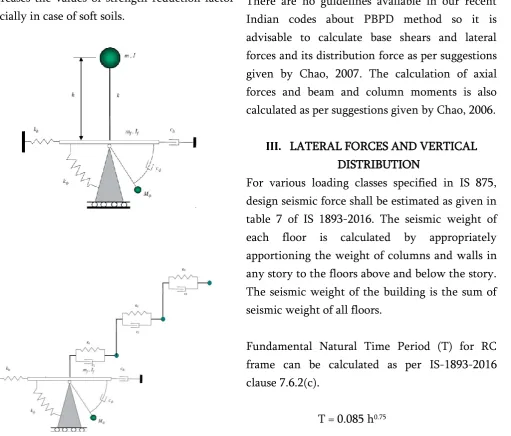
In the past some decades, may studies have been conducted on Strength reduction factor (Rμ). It was seen that when soft soil is consider there is significant effect of strength reduction factor on it. It is also observed that SSI have Severe effect on ductility demand of structures. Researchers concluded that Soil structure interaction decreases the values of strength reduction factor specially in case of soft soils.
FIG: Soil structure model for sway and rocking motion for SDOF and MDOF systems.
II. METHEDOLOGY
The Performance-Based Plastic Design Method has suggested by Goel and Chao, 2009. IN PBPD Method the structure is designed for pre-determined target drift and yield mechanism. Due to this prevention of total collapse is done. There are no guidelines available in our recent Indian codes about PBPD method so it is advisable to calculate base shears and lateral forces and its distribution force as per suggestions given by Chao, 2007. The calculation of axial forces and beam and column moments is also calculated as per suggestions given by Chao, 2006.
III. LATERAL FORCES AND VERTICAL DISTRIBUTION
For various loading classes specified in IS 875, design seismic force shall be estimated as given in table 7 of IS 1893-2016. The seismic weight of each floor is calculated by appropriately apportioning the weight of columns and walls in any story to the floors above and below the story. The seismic weight of the building is the sum of seismic weight of all floors.
Fundamental Natural Time Period (T) for RC frame can be calculated as per IS-1893-2016 clause 7.6.2(c).
Where,
h = height of structure (in m)
Selecting a desired Target Yield Mechanism for design earthquake hazard. Figure shows the design yield mechanism of steel moment resisting frame which is subjected to lateral forces and pushed through plastic drift “Δp”.
Fig: Pre-Selected Yield Mechanism of steel Moment Frame
Calculation of shear distribution factor “βi” of each floor. [4]can be done by
βi = =
Where,
βi = Shear distribution factor at level i ,
Vi = Story shear force at level i,
Vn = Story shear force at roof level (nth
level),
wj = Seismic weight at level j ,
hj = Height of level j from base,
wn = Seismic weight at the top level,
hn = Height of roof level from base ,
T = Fundamental time period.
Calculation of Ah (Dimensionless parameter) can
be carried out by following formula
Ah = ( ). .
Where,
θp= global inelastic drift ratio of the structure(θu – θy) ,
θu = Target drift Ratio, θy = Yield drift Ratio,
βi = Shear distribution factor at level I, g = Gravitational Acceleration.
Calculation of Story shear “Vb” [2]
Vb = )* W
Where, ϒ =
Sa, inelastic =
Where,
Vb = Base shear force ,
γ = Energy modification factor ,μs = Structural
ductility Factor = θu / θy ,
θu = Target drift Ratio ,
θy = Yield drift Ratio ,
Rμ = Ductility Reduction factor ,
Sa inelastic = Spectral acceleration due to inelastic response,
Vb = total story shear at base ,
W = Total design Seismic Load.
Rμ is related to time period of structure and can be obtained by using inelastic spectra [8].
Rμ = ai T bi
Where,
T = Fundamental period of the corresponding fixed-base structure,
ai & bi = Constant coefficient, which depend on
ductility ratio, aspect ratio, number story and equivalent frequency.
Calculation of the Design Lateral force “Qn” of
Qn =
Where,
Qn =Lateral Force at nth level (roof level)
Calculation of the Design Lateral force “Qi” of
each level.
Qi = Qn
Where,
Qi =Lateral Force at ith level
Analysis of Beams
Calculation of required plastic moment of column (Mpc)
=
Where,
V’ =
h1 = Height of the first story
Calculation of required moment strength of beam (Mpb)
=
Where,
Qi = Lateral Force at ith level,
hi = Height at ith level,
Mpc = Required plastic moment of column,
βi = Shear distribution factor at level i ,
L = Distance between two column,
Li’= Distance between centers of RBS cuts.
Design of Beams:
After getting required moment strength of beams, beams are to be designed as per IS-800:2007 (clause 8.2 for flexure and clause 8.4 for shear and checked for deflection as per clause 5.6.1.) and Reduced Beam Section is consider as per ANSI/AISC 358-05.
Fig: Reduced Beam Section
0.5bbf a 0.75bbf
0.65d b 0.85d 0.1bbf c 0.25bbf
Where,
bbf = Width of beam flange,
d = Depth of beam section,
a = Distance of cut at the face of column to start of RBS cut ,
b = Length of RBS cut,
c = Depth of cut at center of reduced beam section , Sh = Distance from column face to center
of Reduced beam section cut which is equal to a+b/2.
Calculation of plastic section modulus at the center of RBS (Ze).
Ze = Z – 2ctbf ( d – tbf )
Where,
Ze = Plastic section modulus at center of the
reduced beam section,
Z = Plastic section modulus for full beam cross-section.
Calculation of the probable maximum moment (Mpr) at the center of RBS.
Mpr = Cpr Ry Fy Ze
Where,
Cpr = Factor of peak connection strength
= 1.075 for other beam
Ry = 1.1, which is ratio of expected yield stress to
specified min. yield stress.
Calculation of shear force at the center of RBS: It is determined by free-body diagram of the portion between the center of RBS.
VRBS =
V’RBS =
Fig: Free-Body Diagram between Center of RBS and Face of Column
Calculation of the probable maximum moment at the face of the column can be done by,
Mf = Mpr + VRBS Sh
M’f = Mpr + V’RBS Sh
Analysis of Column:
Calculation of the sum of lateral forces (FL) for
Exterior Column Tree.
FL =
Where,
Mpr = Probable maximum moment at the centre
of RBS,
VRBS = Shear force at the center of RBS ,
Sh = Distance from a column face to the center of
RBS cut = a + b/2 ,
dc = Depth of the column , Mpc = Required plastic
moment of column
=
When i = n, = 0
Calculation the sum of lateral forces (FL) for
Interior Column Tree.
FL =
Where,
V’RBS = Shear force at the center of RBS ,
dc = Depth of the column ,
Mpc = Required plastic moment of column
=
When i = n, = 0
Fig : Free body diagram of exterior and interior column tree
Calculation of Total axial Force on a column section (N) can be done by,
N = OR
N =
Where,
(Pc)i = Axial force on column section
Calculation of Total bending moment on column section (M) can be done by,
M= ( + )( ) + +
After getting the proper design bending moments, shear force and axial force for columns by Free-body diagram, the columns are designed for axial load only as per clause 7.1 of IS 800:2007.
IV. SUMMARY
Proper design methodology for steel moment resisting frames using PBPD method with soil structure interaction proposed by researchers have been briefly reviewed in this paper. It is important to note that in the beginning itself drift control and yielding is taken into account in PBPD method, so at final design steps there is no need for more and lengthy iterative process. It should also be noted that no proper research has been done in the direction of considering soil structure interaction in PBPD method, so more research in this direction is required. The main effect was about Soil structure interaction is that it decreases the value of strength reduction factor specially in case of soft soils.
V. REFERENCES
[1]. H Akiyama, “Earthquake resistant limit state design for cylindrical liquid storage tanks”, Earthquake Engineering, 10th World
Conference ,1992.
[2]. Sutat Leelataviwat, Subhash C Goel and Bozidar Stojadinovic , “Towards performance-based seismic design of structure”, Dept of Civil and Env engg., University of Michigan, Earthquake Spectra, August 1999.
[3]. Soon-Sik-Lee, Subhash C Goel and Shih-Ho-Chao, “Performance-based seismic design of steel moment frames using target drift and yield mechanism”, 13th World Conference on
Earthquake Engineering, Paper No. 266, August 1 2004.
[4]. Shih-Ho Chao , Subhash C Goel and Soon-Sik Lee, “A seismic design lateral force distribution based on inelastic state of structure”, Earthquake Engineering Research Institute, Aug 2007.
[5]. Subhash C Goel, Wen-Cheng Lio, M.Reza Bayat and Shih-Ho Chao, “Performance-based plastic design (pbpd) method for earthquake-resistant structures: an overview”, The Structural Design of Tall and Special Builing., Vol. 21, Oct 2009.
[6]. Subhash C Goel, Shih-Ho Chao, Sutat Leelataviwat and Soon-Sik Lee, “Performa'ce-based plastic design (pbpd) method for earthquake-resistant structures”, 14th World
Conference On Earthquake Engineering, Oct 2008.
[7]. Tomaz Vidic, Peter fajfar and Matej fischinger, “Consistent inelastic design spectra: strength and displacements”, Dept of Civil engg., University of Lgubljana, ”, Earthquake Engineering and structural dynamics,1994
[8]. Behnoud Ganjavi* and Hong HaoIn “Strength reduction factor for MDOF soil–structure systems” the structural design of tall and special buildings Struct. Design Tall Spec. Build. (2012) Published online in Wiley
Online Library