Themed Section : Engineering and Technology DOI : https://doi.org/10.32628/IJSRSET2184116
Effect of Failure Rate on the Availability Analysis of Nestle
CERELAC Plant Using Markov Chain Method
Gurbinder Singh, Dr. Rakesh Kumar1
M.Tech, MRSPTU, Bathinda, Department of Mechanical Engineering, North West Group of Institutions, Dhudike, Moga, Punjab, India
2Department of Mechanical Engineering, North West Group of Institutions, Moga, Punjab, India
ABSTRACT
In the performance analysis of production systems by using the traditional methods of engineering the knowledge of machine reliability factors is assumed to be precisely known. The current study entitled performance evaluation of food industry in India. To analyze and determine the availability of plant a case study has been undertaken from Moga Nestle food private limited industry in India. Various studies evaluating the performance of automated production systems with the help of modeling and simulation and analytical methods have always given priority to steady state performance as compared to transient performance. Production systems in which such kind of situations arises include systems with dysfunctional states and deadlocks, not stable queuing systems. This research work presents an approach for analyzing the performance of unreliable manufacturing systems that take care of uncertain machine factor estimates. The method that is being proposed is on the basis of Markov chain and probability density function discretization techniques for studying manufacture lines consist unreliable machines. To determine the performance of plant, important information has been collected from different systems and subsystems to find out long run availability of whole system.
Keywords : Maintenance policy, Maintenance, Availability, Replacement, Optimization.
I.
INTRODUCTIONManufacturing flow line systems constitutes material, work areas, and storage areas. Material flows from work space to storage stretch and back again to work space. It visits every work and storage area specifically once in an exceedingly fastened sequence, there is a first work space through that material enters and a half work space through that it leaves the system. Manufacturing flow lines also are known as transfer lines. In this paper, we have a tendency to chiefly use the term „reliability, in General often outlined as the likelihood of a system or device playing its anticipated purpose adequately for the
lower maintenance value which is feasible to boost the provision of the plant with correct maintenance, planning, observance and control. In fact, uninterrupted operation is an important requirement of enormous complicated systems.
II.
SYSTEM DESCRIPTION
In this system, the cerelac is prepared within the rinsed base powder where it is ready for next sub system. In this the tipping area wheat flour sugar, Rework are manually tipped as per the requirement of batch. For the processing of each batch, a weighed quantity of flour and sugar flow to the weighing scale. Any type of impurities or foreign material in held back in the sieve. The flour and sugar with the help of the air from blower now reach the mixer. Jet air filters are installed which prevent any wheat flour being carried away by the air used for its circulation. After passing through various stages of tipping area, different ingredients are then ended in fixed ratios as per recipe. Wheat flour, sugar, water, corn oil, enzyme are mixed here in papenmier.
After being mixed thoroughly, the mixture is now termed as the "soup" Further agitation of soup takes place in the soup vat to bring about homogeneity. The alpha amylase, which is a liquefying enzyme, causes the partial hydrolysis of starch. The amylase enzyme reduces the viscosity of the final product. The soup now flows from the soup vat after agitation for hydrolysis that is an important stage both by process and hygiene point of view. Hydrolysis takes place at a temperature of 70°C by direct steam injection into the soup. The pressure of steam at DSI-I is 1.5Kg/Cm2 .The soup now flows to the hydrolyzing vat Pasteurization of the soup now takes place as it passes after direct steam injection DSI-II. Here the soup is held at a temperature of 132°C for 6.1 sec. This step is CCP-1 in the process as it ensures both safety and quality for the product.
Fig.1 Process flow diagram of base powder preparation
The distribution vat holds the soup that has passed through the two main critical control points of the process. From this distribution vat the soup is now fed to the four roller dryers with the help of their respective product pumps. Dryer Roller important function is to dry the soup by forming a thin layer on the dryer drums and hence remove the moisture. Steam is injected in the hollow drum through the Johnson joint .The surface of the roller dryers is very smoothing devoid of any edges or crevices. The outer surface of the drums is chrome plated. This is to impart the rollers greater strength to avoid wear and tear and also to enhance its surface qualities.
III.
NOTATIONS AND ASSUMPTIONSNotations
𝜆𝑖 : Failure rate of T,P,H,A,D& R units, (i = 1,2,3,4,5,6).
𝜇𝑖 = Repair rate T,P,H,A,D& R units, (i = 1,2,3,4,5,6). o: Represents the system/sub-system is operating. r: Component/sub-system is under repair.
g: Component is working in good condition. s: Laplace transform variable
𝜆𝑖 (t): Represents derivative w. r. t't
Assumptions
a) All the sub-systems are initially operating and all the sub-systems are initially in good state. b) Each unit has two states, good and failed.
c) It is also assumed that there is only one repair facility to handle corrective maintenance. d) Each unit is good as new after repair.
e) The failure rates and repair rates of all units are taken constant.
f) Failure and repair events are statistically
independent.
IV.
MATHEMATICAL ANALYSIS AND
NUMERICAL RESULTS OF THE SYSTEM
Probability consideration gives the following first order differential-difference equations associated with the state transition diagram of sub-system as shown in fig 2.
𝑃′₀(𝑡) + ( 𝜆₁ + 𝜆₂ + 𝜆₃ + 𝜆₄ + 𝜆5 + 𝜆6)𝑃₀(𝑡) = 𝜇₁𝑃₁(𝑡) + 𝜇₂𝑃₂(𝑡) + 𝜇₃𝑃₃(𝑡) + 𝜇₄𝑃₄(𝑡) + 𝜇5𝑃5(𝑡) + 𝜇6𝑃6 (𝑡)
𝑃′₀(𝑡) + 𝛼₁𝑃₀(𝑡) = 𝜇₁𝑃₁(𝑡) + 𝜇₂𝑃₂(𝑡) + 𝜇₃𝑃₃(𝑡) + 𝜇₄𝑃₄(𝑡) + 𝜇5𝑃5 (𝑡) + 𝜇6𝑃6 (𝑡) Where 𝛼₁ = 𝜆₁ + 𝜆₂ + 𝜆₃ + 𝜆₄ + 𝜆5 + 𝜆6
(1)
𝑃′₁(𝑡) + 𝜇₁𝑃₁(𝑡) = 𝜆₁𝑃₀(𝑡) (2)
𝑃′₂(𝑡) + 𝜇₂𝑃₂(𝑡) = 𝜆₂𝑃₀(𝑡) (3)
𝑃′₃(𝑡) + 𝜇₃𝑃₃(𝑡) = 𝜆₃𝑃₀(𝑡) (4)
𝑃′₄(𝑡) + 𝜇₄𝑃₄(𝑡) = 𝜆₄𝑃₀(𝑡) (5)
𝑃5 ′(𝑡) + 𝜇5𝑃5 𝑡 = 𝜆5𝑃₀(𝑡) (6)
𝑃6 ′(𝑡) + 𝜇6𝑃6 𝑡 = 𝜆6𝑃₀(𝑡) (7)
With initial condition at time t = 0 𝑃𝑖 (𝑡) = 1For i = 0
𝑃𝑖 (𝑡) = 0For i ≠ 0
1) Solution of equations
Taking Laplace transformation of equation (1) using initial condition and relation with (8), we get
𝑠𝑃₀(𝑠) + 𝛼₁𝑃₀(𝑠) = 1 + 𝜇₁𝐾₁𝑃₀(𝑠) + 𝜇₂𝐾₂𝑃₀(𝑠) + 𝜇₃𝐾₃𝑃₀(𝑠) + 𝜇₄𝐾₄𝑃₀(𝑠) + 𝜇5𝐾5𝑃₀(𝑠) + 𝜇6𝐾6𝑃₀(𝑠)
(𝑠 + 𝛼₁)𝑃₀(𝑠) = 1 + 𝑃₀(𝑠)(𝜇₁𝐾₁ + 𝜇₂𝐾₂ + 𝜇₃𝐾₃ + 𝜇₄𝐾₄ + 𝜇5𝐾5 + 𝜇6𝐾6 )
𝑃₀𝑠 = {(𝑠 + 𝛼₁) − (𝜇₁𝐾₁ + 𝜇₂𝐾₂ + 𝜇₃𝐾₃ + 𝜇₄𝐾₄ + 𝜇5𝐾5 + 𝜇6𝐾6 )}¯¹ (9) Laplace transformation of availability function A(t) is obtained as
𝐴𝑠 = 𝑃₀𝑠 (10)
Where P₀(s) is given by equation (9)7
Inversion of A(s) gives the availability function A(t)
2) Steady state behavior of sub-system
Now applying steady state condition on first order differential-difference equation setting
𝑡→∞, 𝑑 ⁄ 𝑑𝑡 = 0
The limiting probabilities from equation (1) to (7) are:
𝛼₁𝑃₀ = 𝜇₁𝑃₁ + 𝜇₂𝑃₂ + 𝜇₃𝑃₃ + 𝜇₄𝑃₄ + 𝜇5𝑃5 + 𝜇6𝑃6 (11)
𝜇₁𝑃₁ = 𝜆₁𝑃₀ (12)
𝜇₂𝑃₂ = 𝜆₂𝑃₀ (13)
𝜇₃𝑃₃ = 𝜆₃𝑃₀ (14)
𝜇₄𝑃₄ = 𝜆₄𝑃₀ (15)
𝜇5𝑃5 = 𝜆5 𝑃0 (16)
𝜇6𝑃6 = 𝜆6 𝑃0
Solving these equations recursively, we get
(17)
𝑃𝑖 = 𝐿𝑖𝑃₀ Where i = 1 to 6 Where
(18)
𝐿𝑖 = 𝜆𝑖 / 𝜇𝑖
The overall steady state availability of Base Powder preparation sub-system when running at full capacity is given by:
V.
PERFORMANCE ANALYSIS
The effects of failure rate of various components and sub components comprising the sub-system are examined and their impact on availability is described in following tables.
(A)Effect of failure rate of Tipping unit on availability (AFC):
Taking, 𝜆₂ = 0.006, 𝜆₃ = 0.001, 𝜆₄ = 0.003, 𝜆5 = 0.01 , 𝜆6 = 0.0008 & 𝜇₁ = 0.2, 𝜇₂ = 0.25, 𝜇₃ = 0.33, 𝜇₄ = 0.2, 𝜇5 = 0.125, 𝜇6 = 0.08
Table 1 Steady state availability versus failure rate of Tipping unit
𝜆₁ 0.002 0.004 0.006 0.008
AFC 0.8756 0.8680 0.8606 0.8532
(B)Effect of failure rate of Papenmier unit on availability (AFC):
Taking, 𝜆₁ = 0.002, 𝜆₃ = 0.001, 𝜆₄ = 0.003, 𝜆5 = 0.01 , 𝜆6 = 0.0008 & 𝜇₁ = 0.2, 𝜇₂ = 0.25, 𝜇₃ = 0.33, 𝜇₄ = 0.2, 𝜇5 = 0.125, 𝜇6 = 0.08
Table 2 Steady state availability versus failure rate of Papenmier unit
𝜆₂ 0.006 0.012 0.018 0.024
AFC 0.8756 0.8576 0.8403 0.8237
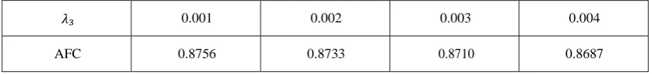
(C)Effect of failure rate of Hydrolysis unit availability (AFC):
Taking, 𝜆₁ = 0.002, 𝜆₂ = 0.006, 𝜆₄ = 0.003, 𝜆5 = 0.01 , 𝜆6 = 0.0008 & 𝜇₁ = 0.2, 𝜇₂ = 0.25, 𝜇₃ = 0.33, 𝜇₄ = 0.2, 𝜇5 = 0.125, 𝜇6 = 0.08
Table 3 Steady state availability versus failure rate of Hydrolysis unit
𝜆₃ 0.001 0.002 0.003 0.004
AFC 0.8756 0.8733 0.8710 0.8687
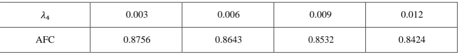
(D)Effect of failure rate of Pasteurization unit on availability (AFC):
Table 4 Steady state availability versus failure rate of Pasteurizing unit
𝜆₄ 0.003 0.006 0.009 0.012
AFC 0.8756 0.8643 0.8532 0.8424
(E) Effect of failure rate of Distribution unit on availability (AFC):
Taking, 𝜆₁ = 0.002, 𝜆₂ = 0.006, 𝜆₃ = 0.001, 𝜆₄ = 0.003 , 𝜆6 = 0.0008 & 𝜇₁ = 0.2, 𝜇₂ = 0.25, 𝜇₃ = 0.33, 𝜇₄ = 0.2, 𝜇5 = 0.125, 𝜇6 = 0.08
Table 5 Steady state availability versus failure rate of Distribution unit
𝜆5 0.01 0.02 0.03 0.04
AFC 0.8756 0.8183 0.7680 0.7236
(F)Effect of failure rate of drying roller unit on availability (AFC):
Taking, 𝜆₁ = 0.002, 𝜆₂ = 0.006, 𝜆₃ = 0.001, 𝜆₄ = 0.003, 𝜆5 = 0.01 & 𝜇₁ = 0.2, 𝜇₂ = 0.25, 𝜇₃ = 0.33, 𝜇₄ = 0.2, 𝜇5 = 0.125, 𝜇6 = 0.08
Table 6. Steady state availability versus failure rate of drying roller
𝜆6 0.0008 0.0016 0.0024 0.0032
AFC 0.8756 0.08680 0.8606 0.8532
VI.
RESULTS AND DISCUSSION
The analysis of base powder preparation sub-system yields that with the increase in failure rates of tipping unit, papenmier unit, hydrolysis unit, pasteurization unit, distribution unit and dry roller the availability of the system reduces. This effect is shown in table 3.1 to 3.6. The reduction in availabilities of the system are found as 2.24%, 5.19%, 0.69%, 3.32%, 15.2% and 2.24% on increasing the failure rates of the tipping unit, papenmier unit, hydrolysis unit, pasteurization unit, distribution unit and dry roller from 0.002 to 0.008,0 .006 to 0.024, 0.001 to 0.004, 0.003 to 0.012, 0.01-0.04, 0.0008 to 0.0032 per hour respectively. From this it is concluded that the distribution unit is the most important factor for the increase of failure rate that affect the system availability.
VII.
REFERENCES
[1]. R.Ahmadia,"An optimal replacement policy for complex multi-components systems" International Journal of production Research, Volume 54 Issue 17, 2016, pages 5303-5316. [2]. Balram joshi (2016), "Performance modeling
and availability analysis of cane Juice extraction system of sugar industry". IRD publications Volume Issue 5-6 pp I-16
[3]. Navkiran Singh (2016), "Performance analysis or various sub system of process plant using markov chain method" IRD Publications volume Issue 5 pp 6-10
Engineering & System Safety, Volume 149. Pages 204-217
[5]. Viswanathan Arunachalam et al (2015) "Some Useful Approximations for the Availability Function", International journal of Reliability, Quality and safety Engineering volume 22, Issue 02
[6]. Zhaojunet at (2015), "Multi-objective and Multi-stage Reliability Growth Planning in Early Product Development stage", IEEE Transactions on Reliability, volume 6s. Issue 2 Pages769.
[7]. Tarun Kumar Garg (2015), "Applications of CAS maxima to the availability analysis of screening unit in a paper plant", International journal of computer and mathematical sciences vol4, issue 6
[8]. Kapil and Sanjay(2014), "Performance analysis of a selected system In a process industry, "International journal of current Engineering and Technology .issue 2 pplo4-108
[9]. Kumar and Garg (2014), "Performance modeling and availability analysis of Malt screener system in a brewery plant", MNK publications. Vol 13 pp 201 209