RESEARCH ARTICLE
ELECTRIC FIELD STRENGTH ALONG A THIN VERTICAL WIRE ON THE EARTH'S SURFACE
1,2*
Ghada M. Sami and
2Mnerh N. Al-qahtani
1
Department of Mathematics Faculty of Science, Ain shams University, Cairo, Egypt
2Department of Mathematics and Statistics Faculty of Science and Arts, Damam University, KSA
ARTICLE INFO
ABSTRACT
In this paper, we will perform theoretical and numerical analysis of the electric field strength along a thin vertical wire on the earth's. The wire is assumed to be placed vertical to the earth’s surface in a stratified homogeneous medium, which is represented by a finite set of horizontal plane layers characterized by conductivities. The electromagnetic properties of the electric field will be reviewed and a solution will be given for the boundary value problem of a wave propagating, the displacement current in free space is negligible. Numerical results are represented graphically.
Copyright © 2015 Ghada M. Sami and Mnerh N. Al-qahtani. This is an open access article distributed under the Creative Commons Attribution License, which permits unrestricted use, distribution, and reproduction in any medium, provided the original work is properly cited.
INTRODUCTION
The study of wave propagation in the earth has a history that extends back to the beginning of the last century and is an interesting topic. Most of the investigations are based on the rigorous theoretical solutions of Sommerfeld, 1926 and Weyl, 1919 for a vertical antenna over a flat homogeneous semi-infinite conducting earth. Practical formulas, valid at large distances from the antenna, are based on the use of asymptotic expansions. All treatments of the phenomenon of the wave propagation took the earth surface as a perfectly smooth (planar or spherical) interface between the air and ground or water. Feinberg, 1944 published a result derived from an integral equation that dealt with the problem of radiation above a planar earth with terrain irregularities. He showed that the effect of small height irregularities would decrease the apparent conductivity of the earth. Details of his derivation were not published, and his result did not show the effect of that finite earth conductivity; the term accounting for roughness was obtained
as though the surface is perfectly conducting. Bremmer,1958 repeated Feinberg’s result.
Natural propagation can be helpful to solve some specific problems, such as radio communications in mines with rooms and pillars which cannot be solved easily with the help of transmission lines. Natural propagation modes are also useful for short range communications, for example, in some road tunnels. Recently, Zheng, 2013 studied the wave propagation theories and application. The case in which the wire is parallel to the plane interface between two homogeneous half-spaces is of particular interest in a number of technical and physical applications. Early attempts Carson, 1926 and Wise, 1934 to solve the problem were based on transmission line analogies that led to useful results, particularly at the low frequency end of the spectrum. Similar developments are found in Sunde, 1949 excellent text on earth conduction effects in power-line systems. More recent works have dealt with the
high frequency behavior (kikuchi,1956). The first use of full wave theory for a wire above a two - layer medium was presented by
Kuesterand Chang, 1977.
Many efforts to develop models for the stratified earth structure are reported in the literature. They are mainly focused on the
calculation of the earth return impedances and each of them uses different concepts and approximations. Nakagawa’s multilayered
earth model (Nakagawa, 1981) can be assumed as the most generalized, since it allows different electromagnetic properties for each earth layer.
*Corresponding author:Ghada M. Sami,
Department of Mathematics Faculty of Science, Ain shams University, Cairo, Egypt.
ISSN: 0976-3376
Asian Journal of Science and Technology Vol. 6, Issue 05, pp. 1458-1463, May, 2015ASIAN JOURNAL OF
SCIENCE AND TECHNOLOGY
Article History:
Received 09th February, 2015
Received in revised form 19th March, 2015
Accepted 30th April, 2015
Published online 31st May, 2015
Key words:
However, the accuracy of these models is limited to the low frequency range, especially for cases of high earth resistivity, since they all neglect the influence of the imperfect earth on the shunt admittances. Furthermore, Ametani, 2001 proposed formulas for the shunt admittances in the case of a two-layer earth. Wait, 1970, computed the propagation constant for a straight wire of infinite length located in a stratified media, and studied the electromagnetic waves in stratified media. Also, Samir Mahmoud and Wait, 1974 studied that wave propagation along a thin wire located inside a rectangular waveguide with imperfectly reflecting boundaries. Coleman, 1950 studied the wave propagation for the case of a thin wire on the interface between two semi-infinite homogeneous media. Recently, Robert, 2000 studied the electromagnetic wave propagation on a thin wire above earth. Yingkang et al. (2010) obtained the wave propagation along a thin vertical wire antenna placed in a horizontally layered media and
Manjunath et al. (2012) studied the wave propagation in random granular chairs. In this paper, the current on the wire, for a
localized generator, it can be constructed by a linear superposition of exponential current modes. In addition, a solution will be given for the boundary value problem of a wave propagating along a thin vertical wireon the earth’s surface. To solve the
boundary value problem, we let that the wire carries a current of the form and is the propagation constant that is to
be determined in terms of the series impedance and series admittance of the wire Lavrov and Knyazev, (1965).The aim of this paperis to perform theoretical and numerical analysis of theelectric field strength along a thin vertical wire on the earth's.In addition, we will use the available numerical methodsto obtain the results of the imaginary part of the electric field and represented graphically.
The Method of the Solution
We consider the problem as shown in Figure (1), we assume that the wire very thin compared to its length. In medium 1, the
permittivity and permeability of free-space are and , respectively. The wire is vertical on the interface has height
h. In medium 2, the permittivity and permeability are , , respectively. We chosen a Cartesian coordinate system (x, y, z) and
oriented along the positive z-axis and located at y = h and x = 0.
Thus, for the solution of the boundary value problem, we let the current have the form , where is the propagation
constant.
The Electric Field Due to the Current .
The primary fields of the infinite wire can be derived from the potential given by Wait, 1985
……… (1)
The components and are the electric and magnetic Hertz vectors respectively, the integral representation for the Hertz potentials in medium 1 and 2, take the form ……… (2)
……….. (3)
………. (4)
……….. (5)
The wave numbers and for the two media, are
It is convenient in the present problem to express the total electric field in terms of two scalar potentials. In medium 1, the electric
field has the components:
……… (6)
……… (7)
………. (8)
and in medium 2,
……… (9)
………. (10)
……….. (11)
The boundary conditions require at y = 0that and .From equations (2)-(5), with the
boundary conditions can be can be applied to obtain the unknown functions R , as:
………
(12)where in the caseof , equation (12) leads to
……… (13)
Using this result in equation (13), we can now obtain an explicit expression for the total axial electric field in the upper half –
space due to the current in the wire, from the equation (8) we can get
... (14)
We are substituting the value of from equation (13) in equation (2), we obtain
, ……… (15)
by substituting for in the above equation, then
……….. (16)
………... (17)
then, the expressions of the electric field in the upper half – space due to the current is
……….. (18)
where,
………. (19)
Numerical Results
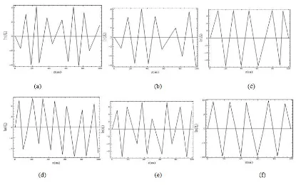
A theoretical and numerical analysis of the electric field along a thin vertical wire on the earth's surface have been studied. The
wire is assumed to be placed vertically on the earth's surface, and the electric field component is obtained in terms of the
propagation constantthe direction of the propagation is an a z-direction. The imaginary part of the electric field component has
been plotted as shown in Figure 2((a, b, c) – (e, d, f)), and Figure3 ((a, b, c) - (e, d, f)) due to the rate of variation of the phase of
the wave, and along z-direction, at the distance source from the earth's surface h = 250 m and 400 m with
different frequencies f = 50 MHz, 130 MHz and 200 MHz, respectively. According to these Figures, it is clear that the values of
the imaginary part of the electric field component increase with increasing distance h; the frequency is increasing. The values
of the imaginary part of the electric field component in the case when the rate of variation of the phase of the wave along z
-direction (see Figures 2 (a, b, c) and (e, d, f)) are less than when , (see Figures 3 (a, b, c) and (e, d, f)).
The imaginary part of the propagation constant , with frequency 200 MHz at a high distance 400m, which is first small
peak compared to the cut-off frequency of the first mode, while the greater first peak compared to the cut-off frequency of the first
mode when the imaginary part of the propagation constant at the same distance 400m.However, the values of the
imaginary part of the electric field component is stable at a high frequency 200MHz and for different distance, h = 250 m, and
400 m, then the received signal becomes constant.
Figure 3. ((a, b, c)- (d, e, f)). Representation of the imaginary part of the electric field component due to propagation constant ath= 250m, 400 m, for the frequency f = 50MHz, 130MHz and 200MHz, respectively.
Conclusion
We conclude that the imaginary part of the electric field depend on the rate of variation of the phase of the wave , which is the
rate of variation of the phase of the wave along the z coordinate will be reviewed and a solution will be given for the boundary
value problem of a wave propagating. It is related to the wave length and to radian frequency, and it is measured in rad / m.The
result of imaginary part of the electric field component has been calculated due to the imaginary part of the propagation
constant for the two cases when , the results are represented graphically. The direction of the propagation is
in a z-direction, then the waves has only z-component of the electric field. The displacement current in free space is negligible and some numerical results represented graphically.
REFERENCES
Sommerfeld, A. 1926. “On the propagation of waves in wireless telegraphy”, Ann. Phys., 25, pp. 665-736, 1909; and 81, pp. 1135-1153,
Weyl, H. 1919. Ausbreitungelektromagnetischerwellenubereinemebenenleiter, Ann. Physik, Ser. 4, vol. 60, pp. 481-500. Feinberg, E. 1944. On the propagation of radio waves along an imperfect surface, J. Phys. (Moscow), vol. 8, pp. 317-330, Bremmer, H. 1958. Propagation of electromagnetic waves, Hand b. Phys., Ch. 16, pp. 423-639.
Zheng, Y. 2013. Wave propagation Theories and Applications, InTech.
Carson, J. R. 1926. “Wave propagation in overhead wires with ground return”, Bell Sys.Tech. J., 5, 539-554.
Wise, W. H. 1934. “Propagation of HF currents in ground return circuits”, Proc. Inst. Elec. Eng. (London), 22(4), 522-527. Sunde, E. 1949. ”Earth Conduction Effects in Transmission Line Systems”, Van Nostrand, New York.
kikuchi, H. 1956. “Wave propagation along an infinite wire above ground at high frequencies”, Electrotech. J. Japan, 2(3/4), 73-78,
Kuester, E.F. and Chang, D.C. Dec.1977. "Propagating modes along a thin wire located above a grounded dielectric slab", IEEE
Trans. Microwave Theory Tech., Vol. MTT-25, PP.1065-1069.
Nakagawa, M. Jul. 1981. “Further studies on wave propagation along over head transmission lines: Effects of admittance
correction,” IEEE Trans. Power Syst., vol. PAS-100, no. 7, pp. 3626–3633.
Ametani, A. Nagaoka, N. and Koide, R. 2001. “Wave propagation characteristics on an overhead conductor above snow,” Trans.
Inst. Elect. Eng. Japan, vol. 134, no. 3, pp. 26–33.
Wait, J. R. 1970. Electromagnetic Waves in Stratified Media, chap. 6, pp. 132-195, Pergamon, New York.
Samir Mahmoud, F. and Wait, J. R. March 1974. “Theory of wave propagation along a thin wire inside a rectangular waveguide”, Radio Science, Volume 9, Number 3, pages 417-420.
Coleman, B. L. 1950. “Propagation of electromagnetic disturbances along a thin wire in a horizontally stratified medium”, Phil. Mag., $er. 7, 41, 276-288.
Robert, G. O. Jeffrey, L. Y.and David, C. C. , 2000. “Electromagnetic Wave Propagation on a Thin Wire above Earth” IEEE
Yingkang, W., Bengt, H., Ingve, S. and Lars, N. 2010. “Wave Propagation Along a Thin Vertical Wire Antenna Placed in a Horizontally Layered Media”, ACES, Vol. Fundamental Electromagnetic: Materials and Boundaries.
Manjunath, M., Awasthi, P. and H. Geubelle, 1965. "Wave propagation in random granular chains", Phys. Rev. E85,031308,2012. Lavrov, G. A. and Knyazev, A. S. “Near Earth and Buried Antennas”, Soviet Radio Press, Moscow.
Wait, R.J. 1985. Electromagnetic waves theory, Harper & Row, New York.