Study of Plasma Equilibrium Control for JT-60SA using MECS
∗
)
Yoshiaki MIYATA, Takahiro SUZUKI, Shunsuke IDE and Hajime URANO
Japan Atomic Energy Agency, 801-1 Mukoyama, Naka, Ibaraki 311-0193, Japan
(Received 6 December 2013/Accepted 12 March 2014)
A magnetohydrodynamic equilibrium control simulator (MECS) has been developed to study the techniques of plasma equilibrium control in JT-60SA. The new modules of the plasma shape reconstruction, power supply, and simulated poloidal field coils are incorporated into MECS to simulate plasma equilibrium control considering the power supply capability and the influence of the identification error between the actual and reconstructed plasma boundary, just as in a real plasma experiment. The MECS uses the Cauchy condition surface (CCS) method for plasma shape reconstruction. Plasma equilibrium control is demonstrated during the heating phase along with the CCS method and power supply capability.
c
2014 The Japan Society of Plasma Science and Nuclear Fusion Research
Keywords: JT-60SA, MECS, plasma equilibrium control, Cauchy condition surface method, isoflux technique DOI: 10.1585/pfr.9.3403045
1. Introduction
The precise control of plasma equilibrium such as its position, shape, and plasma currentIPis essential for safe and stable plasma operation. As is well known, the elon-gation and triangularity of plasma shape are closely related to the energy confinement performances. Furthermore, the clearances between the plasma and the first wall, the strike points of the separatrix on the divertor plate, must be con-trolled from the view-points of the operational objectives and device protection. To achieve stable plasma operation, it is essential to develop a simulator that is close to real plasma experiments. The simulator consists of a plasma control system, a plasma shape reconstruction system, a tokamak simulator. The tokamak simulator has modules for simulated plasma, actuators and diagnostics to simu-late a real tokamak device. It is possible to predict plasma behavior in an operation scenario before a real plasma ex-periment. In addition, it is also useful to develop an ad-vanced controller for simultaneous control of the plasma parameters.
A magnetohydrodynamic (MHD) equilibrium con-trol simulator (MECS) has been developed to study tech-niques for plasma equilibrium control in JT-60SA [1–3]. A plasma shape reconstruction system had not been incor-porated in the previous MECS, and the power supply ca-pability had not been taken into account in the tokamak simulator. Since several new modules have been incorpo-rated into the MECS, it is possible to investigate plasma responses to dynamic changes in the plasma equilibrium with the power supply capability and the influence of the identification error between the actual and reconstructed last closed flux surface (LCFS). Consequently, the MECS
author’s e-mail: [email protected]
∗)This article is based on the presentation at the 23rd International Toki
Conference (ITC23).
produces a better simulation of plasma equilibrium control, just as in a real plasma experiment.
Section 2 describes the modification of the controller and the outline of new modules such as the plasma shape reconstruction, power supply, and simulated poloidal field (PF) coils. The simulation of plasma equilibrium control in response to a prescribed change in the internal parameters of the plasma with new modules using MECS is described in Section 3. A summary is presented in Section 4.
2. Outline of MECS
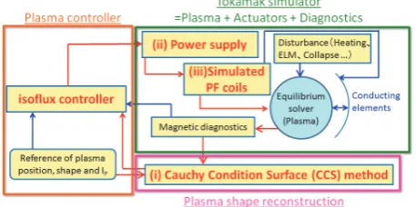
The MECS consists of modules as shown in Fig. 1. The equilibrium solver predicts the plasma equilibrium and unknown eddy current under the given coil current by iter-ation. The MECS uses an isoflux controller for plasma equilibrium control, which modifies the coil currents to reduce the residual between the poloidal magnetic flux at the LCFS and that at the control points which specify the plasma position and shape [4]. The controller also changes the poloidal flux equally at all control points to reduce the difference between the actual and reference values of IP.
Fig. 1 Calculation flow of the MECS.
c
2014 The Japan Society of Plasma
In this study, new modules for the plasma shape recon-struction, the power supply, and the simulated PF coils are incorporated in order to simulate real plasma experiments.
2.1
Module for plasma shape reconstruction
It is necessary for the tokamak device to reconstruct the LCFS and calculate the quantities related to plasma shape to control the plasma equilibrium in real-time. The LCFS can be reconstructed by using the plasma shape re-construction from the magnetic diagnostic signals. How-ever, it is known that plasma shape reconstruction has an identification error between the actual and reconstructed LCFS due to the effects of eddy current, diagnostic noise and so on. Since this identification error causes excessive control of the actuator, it is expected that plasma equilib-rium control becomes unstable. The MECS incorporates the Cauchy condition surface (CCS) method as the plasma shape reconstruction to simulate the real plasma experi-ment.The CCS method is a numerical approach to recon-struct the plasma boundary and calculate the quantities re-lated to the plasma shape in real-time [5]. The features of the CCS method are as follows: (a) acquiring the exact so-lution from the actual values of the PF coil currents and magnetic diagnostic signals, (b) estimating and including the effect of eddy currents flowing in the tokamak struc-tures, and (c) having a short calculation time for real-time control. The CCS method incorporated into the MECS re-ceives signals for the PF coil,IP, magnetic probes (MPs) and flux loops (FLs) from the magnetic diagnostics mod-ule, and it reconstructs the LCFS and calculates the eddy currents flowing in the tokamak structures.
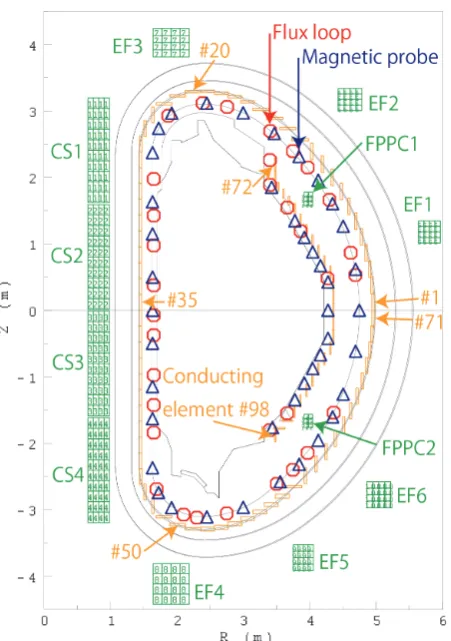
Since the eddy currents are induced by changes in the PF coil currents, IP, and the plasma position, the circuit equations are solved by calculating the induced voltages due to the mutual interactions among them. In addition, the CCS method uses the positions of the control points re-ceived from the controller and evaluates the poloidal flux at the LCFS and at the control points for plasma equilibrium control. JT-60SA has 10 PF coils and 2 fast plasma posi-tion control (FPPC) coils as shown in Fig. 2. The PF and FPPC coils are superconducting and in-vessel copper coils, respectively. The PF coils comprise 4 central solenoid (CS) modules and 6 equilibrium field (EF) coils. To estimate the values of the eddy currents, the vacuum vessel and stabi-lization plate are modeled as 71 and 27 one-turn toroidal conducting elements, respectively, with constant electrical resistivity. The 34 FLs and 45 MPs are used for plasma shape reconstruction in this calculation. After reconstruc-tion, the CCS method provides the position of the X point, the poloidal flux value at the LCFS, and that at the control points to the controller in order to control the plasma equi-librium. The evaluated eddy currents and position of the plasma current centroid are used to calculate the command voltagesVcoil-comof PF coils in the controller.
Fig. 2 Locations of the PF coils, conducting elements, magnetic probes and flux loops used for plasma shape reconstruc-tion in JT-60SA.
2.2
Consideration of power supply
capabil-ity
A plasma equilibrium control simulation should con-sider power supply capability because the power supply limits the voltage and current to the PF coils. It is expected that the controller fails to control the plasma equilibrium accurately as the voltages or currents of the PF coils reach that limit. The previous controller provides the reference currentsIcoil-refof the PF coils as the actual induced cur-rentsIcoil-actof those coils to the equilibrium solver without considering the power supply capability [6]. In this study, the controller is modified and the modules of the power supply and simulated PF coils are incorporated to consider the power supply capability.
First, Icoil-refis calculated using the isoflux technique in the controller, which uses proportional-integral (P-I) feedback control. The controller calculatesIcoil-ref to re-duce two controlled quantitiesδΨSandδΨXaccording to the following equation:
Icoil-ref(t+ ΔtPF)=Icoil(t0)+M†PF
GSPδΨS(t) +GSI
t
t0
δΨS(t)dt+GXPδΨX(t)
+GXI t
t0
δΨX(t)dt
whereδΨSis the residual between the poloidal flux value at the LCFS and that at the control points;δΨXis the dif-ference between actual value ofIPand its reference;t0is the initial time; ΔtPF is the control cycle for the PF coil; M†PFis the (m×(n+1)) control matrix which is the gen-eralized inverse of the Green functionM calculated using the singular value decomposition method; mis the num-ber of PF coils;nis the number of control points;GSPand
GSI are the respective control gains for the P-I feedback controls required for controlling the plasma position and shape; andGXP andGXI are the respective control gains for the P-I feedback controls required for theIP control. The units of the variables are as follows:GSPandGXPare dimensionless, andGSIandGXIare in s−1. It is necessary for consideration of the limit voltage of power supply to calculateVcoil-com converted from Icoil-ref in the modified controller. The measured voltagesVcoil-measof PF coils are defined only by the mutual interactions among the PF coils, conducting elements, and plasma because the resistance of the PF coils is zero. SinceVcoil-com is also calculated by considering the mutual interactions among them, the actual values of the PF coil currents, IP, the eddy currents, and the mutual inductances are required to calculateVcoil-com in the controller. In a real plasma experiment, the values of the eddy currents and the mutual inductances among the plasma and the PF coil are unknown because it is difficult to measure them directly. Therefore, they are provided by the CCS method.
Secondly, the power supply module is incorporated to consider the power supply capability. It evaluates the ac-tual applied voltageVcoil-act to the PF coil from Vcoil-com within the power supply capability. AlthoughVcoil-actis in agreement withVcoil-comwithin the limit voltageVcoil-limof the power supply,Vcoil-actis fixed atVcoil-limifVcoil-comis greater thanVcoil-lim.
Finally, the simulated PF coil module is incorporated to evaluateIcoil-act. It evaluates Icoil-act induced in the PF coils by Vcoil-act by the mutual induction among the PF coils, conducting elements, and plasma. The value of Icoil-actis provided to the equilibrium solver for solving the plasma equilibrium.
3. Simulation of Plasma Equilibrium
Control
The plasma equilibrium control is simulated in the heating phase during which an attempt is made to main-tain a constant plasma and shape while the poloidal beta
βPand internal inductanceliare changed.
3.1
Simulation with CCS method
Normally, the plasma shape changes in response to changes in plasma internal parameters such asIP,βP, andli. Changes inβPandlioccur not only at the start and end of the heating phase but also during certain MHD activities, the collapse, and so on. The controlled plasma
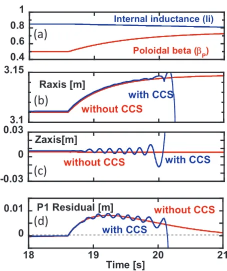
parame-Fig. 3 Waveforms of (a) actual value ofβPandli, (b)Raxis, (c)
Zaxis, and (d) P1 residual without and with CCS.
ters are as follows:IPis maintained at close to 5.5 MA,βP increases exponentially from approximately 0.50 to 0.75 with a time constant of 1 s, andlidecreases linearly from 0.84 to 0.75 with the divertor configuration. All the equi-librium calculation cycles and control cycle of the PF coils are 5 ms. The values ofGSP,GXP,GSI, andGXIare 1.2, 3.0, 1.0, and 10.0, respectively, in the following simulation. It is known that a largeGSP reduces the maximum residual induced by the change in the plasma parameters. The in-fluence of the identification error on plasma equilibrium control is investigated by a comparative simulation with-out and with the CCS method. In the simulation withwith-out the CCS method, the quantities required for plasma equi-librium control and calculation of Icoil-act are calculated from the equilibrium. However, in the simulation with the CCS method, they are reconstructed from the CCS method which has an identification error.
Figure 3 shows the waveforms of the plasma param-eters, positions of the magnetic axis, and the P1 residual without and with the CCS method. TheβPandliare fixed at the given reference values as shown in Fig. 3 (a). Ini-tially,Raxisincreases owing to the increase inβPas shown in Fig. 3 (b). Although Zaxis without CCS is almost un-changed owing to the increase inβP,Zaxiswith CCS fluc-tuates as shown in Fig. 3 (c). The P1 residual with CCS increases by up to 8 mm att =19.2 s, and it also fluctu-ates as shown in Fig. 3 (d). It is found that the stability of plasma equilibrium control decreases under the influence of the identification error in these conditions.
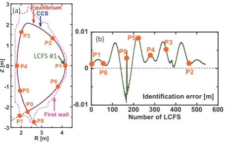
in-Fig. 4 (a) LCFS by equilibrium and CCS att=18.0 s. (b) Pro-file of the identification error between actual and recon-structed LCFS att=18.0 s.
fluence on plasma equilibrium control. Figure 4 (a) shows the locations of the control points, the first wall, and the LCFS by equilibrium and CCS att=18.0 s. The number of LCFSs increases from the mid-plane of the low field side in a clockwise direction as shown in Fig. 4 (a). Since the MECS solves the plasma equilibrium and provides mag-netic diagnostic signals to the CCS, the LCFS from the equilibrium is equal to the actual LCFS. Figure 4 (b) shows the profile of the identification error between actual and re-constructed LCFS att =18.0 s. It is found that the iden-tification error is within 0.01 m and varies widely depend-ing on the position. Especially, it is large at the positions which are far from the magnetic diagnostics. Because the identification error at each control point including the re-constructed X point (P0 – P8) is different, an incorrect con-trol is applied. If the concon-trol gains for position and shape are large, an incorrect control is also sharply applied to the actual X point and the plasma surface. Therefore, the iden-tification error should be reduced by modifying the plasma shape reconstruction for stable plasma equilibrium control. Then, the dependence of control gain is investigated to mitigate the influence of the identification error on plasma equilibrium control. The value ofGXP is decreased from 1.2 to 0.5 in order to apply the incorrect control to the actual X point and plasma surface gently, and other con-trol gains are fixed. Figure 5 (a) shows the locations of the control points and LCFS by CCS att =18.0 and 26.0 s. Figures 5 (b) - (e) show the waveforms of the plasma pa-rameters, positions of magnetic axis, and P1 residual with-out and with the CCS method. The waveforms ofRaxis andZaxiswith CCS are in close agreement with those with-out CCS as shown in Figs. 5 (c) and (d). The P1 residual with CCS increases by up to 11 mm att=19.1 s, and it de-creases and approaches zero over time owing to the control of the plasma position and shape as shown in Fig. 5 (e). It is found that the stability of the plasma equilibrium control increases by decreasing the control gain of plasma position and shape even if there is an identification error. However, the control gain for plasma position and shape is too small
Fig. 5 (a) Locations of the control points and LCFS by CCS at
t=18.0 and 26.0 s. Waveforms of (b) actual value ofβP andli, (c)Raxis, (d)Zaxis and (e) P1 residual without and with CCS.
Fig. 6 Waveforms of (a) the actual value ofβPandli, the com-mand voltages of (b) EF1 – EF3 and (c) EF4 – EF6. (d) LCFS by the CCS att=18.0, 19.0 and 19.5 s.
to control the change in the plasma due to the change in the plasma parameters. An appropriate control gain can be optimized to achieve stable plasma operation by using the MECS.
3.2
Simulation with power supply capability
The controllability of plasma equilibrium is investi-gated with the power supply capability. It is expected that the voltage of the PF coil reaches its limit voltage due to the rapid change inβP. The controlled plasma parame-ters are as follows: IP is maintained at close to 5.5 MA,keeps moving outward, and the LCFS fluctuates at the up-per region where the gradient of poloidal flux is low, while Vcoil-act reachesVcoil-lim. It is shown that the MECS can simulate plasma behavior considering the power supply ca-pability. A stable operation scenario within the machine capability can be optimized by using the MECS.
4. Summary
The new modules for plasma shape reconstruction, power supply, and simulated PF coils are incorporated into the MECS to simulate plasma equilibrium control consid-ering the power supply capability and the influence of the identification error between the actual and reconstructed LCFS just as in a real plasma experiment. The MECS employs the CCS method for plasma shape reconstruc-tion. Plasma equilibrium control is demonstrated during the heating phase with the CCS method and power supply capability. It is found that the stability of plasma equi-librium control decreases under the influence of the iden-tification error if the control gains for position and shape
are large. The plasma position keeps moving outward, and the LCFS fluctuates at the upper region where the gradi-ent of poloidal flux is low, whileVcoil-act reachesVcoil-lim. Appropriate control gains and a stable operation scenario within the machine capability can be optimized by using the MECS.
In the future, the positions of the plasma current cen-troid and eddy currents reconstructed by the CCS method will be compared with those calculated by the equilibrium in order to achieve stable plasma operation. The scheme which avoids contact of the plasma with the first wall even ifVcoil-actreachesVcoil-limwill be investigated.