Wearable Sensor Networks for Motion Capture
Dennis Arsenault
School of Information TechnologyCarleton University Ottawa, Canada
DennisArsenault@cmail.carleton.ca
Anthony Whitehead
School of Information TechnologyCarleton University Ottawa, Canada Anthony.Whitehead@carleton.ca
Abstract— This work presents the development of a full body sensor-based motion tracking system that functions through wearable inertial sensors. The system is comprised of a total of ten wearable sensors and maps the player's motions to an on-screen character in real-time. A hierarchical skeletal model was implemented that allows players to navigate and interact with the virtual world without the need of a hand-held controller. To demonstrate the capabilities of the system, a simple virtual reality game was created. As a wearable system, the ability for the us-ers to engage in activities while not being tied to a camera system, or being forced indoors presents a significant opportunity for mobile entertainment, augmented reality and interactive systems that use the body as a significant form of input. This paper out-lines the key developments necessary to implement such a system.
Keywords Sensors; motion capture; active games; exergames; wearable sensors
I. INTRODUCTION
A body area sensor network (BASN) is a network of sen-sors that are used to determine the current state, or changes of state, of an individual. The network is comprised of various sensors that are typically worn on the body, though in special cases they may also be implanted within the body. The type, distribution and number of sensors included vary depending on the specific application requirements.
Figure 1. A theoretical body area sensor network.
Each sensor in the network, sometimes referred to as a node, measures information regarding a particular state of the wearer. This information may then be passed on to a central transmitter also located on the body. This transmitter relays all of the sensors' data to the main processing device. Depending on the design of the network and sensors, this central transmit-ter may be implemented as part of the central processing sys-tem, for example Bluetooth and a mobile device. The basic
design of a theoretical BASN can be seen in Figure 1, which shows the different components and how information is trans-ferred. The main processing device handles the principal calcu-lations and manipulation of the data in accordance with the needs of the application. For much more in depth discussions on BASNs and their various components outside the scope of this writing, the reader can refer to [1] and [2].
A. Body Area Sensors
Technological advances in the last few decades have vastly improved the feasibility of BASNs. Sensors have become much smaller with the development of technologies like Micro-Electro-Mechanical Systems (MEMS), allowing for sensors to be much less encumbering when worn. Wireless technologies have allowed for many of the systems to communicate wire-lessly and operate on batteries, permitting larger areas of opera-tion and easier wearability. Improvements to processing speed have led to faster data handling, allowing real-time applications to be explored. Meanwhile, the rise of devices such as smart phones has permitted the main processing device to become portable, allowing for a wider range of potential applications.
There are a huge number of potential sensors that can be in-corporated into a BASN. These can roughly be divided into two principal categories. The first category is physiological sensors, which detect the state of and changes in physiological properties. The second category is biomechanical sensors that monitor the physical changes such as motion.
1) Physiological Sensors
While not exhaustive, examples of physiological sensors include:
Heart Rate Sensor: Heart rate sensors detect a subject's heart rate in beats per minute, as well as heart rate variability. This is accomplished through chest/wrist bands, finger clips or electrodes. Heart rate is used to detect factors like exertion lev-el [3][4], frustration [5] and engagement in an activity [6].
Galvanic Skin Response Sensor (GSR): The electrical properties of the skin vary depending on the sweat level and the associated eccrine glands [7]. These levels will vary depending on an individual's level of stress or frustration. A galvanic skin sensor on the finger or palm can be used to estimate the change in these emotional states [8][9].
Electromyography (EMG): When muscles contract they produce measurable electrical potentials across the surface of the skin. These potentials can be measured by placing
elec-INTETAIN 2015, June 10-12, Torino, Italy Copyright © 2015 ICST
trodes on the skin's surface near the desired muscle. These sen-sors can be used for measuring voluntary contractions for pur-poseful input, or involuntary contractions to measure frustra-tion or stress [5][10].
Brain Computer Interfaces (BCI): Similar to muscles, the brain emits detectible signals while working. Systems that de-tect these signals using electrodes or other techniques can be applied to record a wide range of signals for either explicit user control [11][12][13] or simple detection purposes [14].
Respiration Sensor: Respiration sensors often make use of a chest band. The chest band expands with the chest to measure both respiration rate as well as volume. These sensors may be used for either a passive or active control schemes [10][15].
2) Biomechanical Sensors
The second category of body sensors are the biomechanical sensors, which are the type of sensor that is used throughout this work. They are used to measure the physical position and movements of an individual. Three of these sensors are of key significance for this work:
Accelerometers: An accelerometer measures any accelera-tion that occurs along the device's axis. Because of this, 3-axis accelerometers are often used to allow accelerations to be measured in any direction. This is accomplished by placing three accelerometers in an orthogonal configuration and is now a standard design in most modern accelerometer sets. Accel-erometers are able to provide information on their angle of in-clination with respect to the downwards direction by sensing the acceleration due to gravity. Unfortunately they are unable to distinguish between this gravitational force and actual accel-erations [17]. While double integration may be performed to obtain positional information, noise makes this extremely diffi-cult and imprecise, even with extensive filtering [18].
Gyroscopes: While accelerometers detect linear accelera-tions, gyroscopes are used to detect angular velocities. Unfor-tunately, gyroscopes lack the capability to determine their ab-solute orientation. While accelerometers suffer most from noise in their readings, even the best quality gyroscopes suffer from drift issues [18]. Drift results in small angular velocities being reported even when the device is stationary. Over time this drift will accumulate and can become a significant issue. Gyro-scopes are especially adept at accurately detecting quick rota-tions rather than long slow rotarota-tions.
Magnetometers: Magnetometers are sensitive to magnetic fields and are often used to discern the direction of the Earth's local magnetic field. A magnetometer can use the Earth's mag-netic field as a reference direction in the same way an accel-erometer uses the directional force of gravity. The Earth's mag-netic field is weak and can be easily disrupted or overpowered by nearby metallic objects or electronics and so care must be taken when using magnetometers [18]. A magnetometer is helpful to eliminate the effects of drift in a gyroscope.
When accelerometers, gyroscopes and magnetometers are used together they are often collectively referred to as an iner-tial measurement unit (IMU). This is due to the way in which they operate, by making use of the physical laws of mass and inertia to determine their motions and orientation. Combining
their output data to obtain a better measure than any one indi-vidual sensor is the topic of sensor fusion.
II. BODY AREA SENSOR NETWORK APPLICATIONS
All of these different sensors can be used in countless com-binations, with the sensors selected to best meet the needs of the application. Health care systems are being examined as a very useful space for BASNs. They can allow for remote moni-toring of patients [16][19], fall detection in the elderly [20], and better physiotherapy treatments [21]. Some military applica-tions are being examined [22][23], as well as professional sports training [24], general exercise promotion [25][26][27], and security authentication and information sharing [2]. In this work we choose to design our system around an entertainment and gaming application. However, our methods and findings are equally applicable to any of the other areas where BASNs may be useful.
There are currently few studies that have looked at using IMU sensors as the primary mode of interaction for gaming. Some commercial products like the Nintendo Wii and Playstation Move make use of biomechanical sensors for gameplay, but only through hand-held controllers with multi-ple buttons. Dance games are a popular immulti-plementation con-sideration for IMU-based input systems.
A. Dance Games
The sensor network for active play (SNAP) system made use of four accelerometers located on the wrists and knees to determine a player's pose [17][28][29]. Incorporating the whole body in this way allowed them to avoid the cheating issues seen with the Wii, where players can simulate full body motions with simple wrist flicks. The SNAP system could sense the inclination angle of the four accelerometers. By comparing these readings to previously trained reference pos-es, the system could determine if a player was matching the desired pose at the right time.
Dance games are one of the most popular types of active game, both in research and commercially. Charbonneau et al. [30] argue that dance game popularity stems from the low barrier to entry and most people's willingness to try them. Their work follows closely to that of the SNAP system. They created their own version of a dance game using four worn Wiimotes on the ankles and wrists. Other dance based games [31][32] also use IMU sensors in some capacity.
B. Non-Dance Games
There have been some non-dance-based games developed that use worn IMUs as well. Wu et al. [33] created a virtual game of Quidditch, a sport from the Harry Potter universe. They used two IMU sensors on the player's arm, as well as one on both their prop broom and club. The player steered by mov-ing their held broomstick and used their arm and club to attack incoming balls. To increase immersion the setup used multiple screens to project the view on multiple sides of the player. However, they do not give many specific details on the sensor based interactions or gameplay.
Both Zintus-art et al. [34] and Mortazovi et al. [35] created games that use a single sensor attached to the player's ear or foot respectively. In [34] they used an accelerometer to deter-mine if the player was running, walking, jumping, or leaning. These actions controlled an on-screen dog character and the player's goal was to avoid oncoming obstacles. Though a very simple setup, they achieved very high recognition accuracy results at almost 99%, with recognition times under a second. Meanwhile, [35] used an accelerometer and pressure sensor combination to control actions in a soccer game. Though the player still made use of a standard controller for some inputs, the worn sensor was involved in the running, passing and shooting actions. They also put significant consideration into protecting the system from being cheated in the same way as the Wii.
These works are still far from tracking full body poses and motions. They all use a low number of sensors, giving them a limited amount of information on the player. While their mo-tion/action recognition methods are suitable and perform well for the requirements of their designed games, they likely would not scale well for much more complex applications than what they have presented.
III. RELATED WORK
Outside of the entertainment space there have been several papers examining the prospect of more detailed motion and position tracking of an individual through the use of worn IMU sensors. Previously, body motion tracking has been pri-marily accomplished through optical means due to its high level of precision. This has been further bolstered by the de-velopment of Microsoft's Kinect system. Though the Kinect lacks the precision of advanced multi-camera systems, it al-lows for easy motion tracking at a more economical cost. The-se optical systems have major limitations though, as they re-quire constant line of sight of the subject and self-occlusion can be problematic. Camera-based systems also suffer when there are poor lighting conditions, require the user to stay within a very stringent operational area and typically are opti-mized for indoor use only.
Motion tracking with IMU sensors is becoming more feasi-ble for the same reasons as BASNs. Elaborate and precise camera setups are very expensive and similar accuracies could
potentially be achieved using a distributed network of IMU sensors across the body. While IMU systems do not currently perform at the same level of precision as optical systems [36], there are many situations where they could still thrive. They may be beneficial where extremely high levels of precision are not required, where cost is a major factor (such as in consumer products), or where the limitations of a camera system are major concerns; especially outdoors.
The motion capture with accelerometers (MOCA) system [37] used accelerometers to detect arm inclination and also made use of very simple gesture recognition. The system comprised only a single accelerometer and their gesture recognition was based on the current inclination angle rather than dynamic motion-based gestures. They used this recogni-tion to allow users to navigate a virtual world using their wrist orientation.
Zhang et al. [38][39] tracked arm motions using a pair of sensors containing an accelerometer, gyroscope and magne-tometer on the upper arm and forearm. In addition to deter-mining the orientation of the arm through their sensor fusion algorithm and an unscented Kalman filter, they also imposed geometrical constraints on the system. These involved biome-chanical factors such as the lack of adduction/abduction movement in the elbow. This helped them to constrain noise and estimation errors in their readings. Their results were very successful compared to the accuracy of an optical tracking system. Similar IMU tracking experiments were also conduct-ed in both [40] and [41].
Body tracking suits were proposed in [42] and [43], with multiple sensors positioned at various points across the body. The former work tested a single instance of their iNEMO sen-sors, comprised of an accelerometer, gyroscope and magne-tometer, against commercial inertial sensors like those by Xsens [44]. Though the iNEMO sensor had lower precision, it still performed well for a significantly smaller cost investment. iNEMO M1 sensors were then used to build a partial full-body tracking suit in [45]. Five sensors were used to track the orien-tations of the forearm, upper arm, torso, thigh and shin on the right side of the user's body. The orientation of these limbs is displayed on a skeletal model in real time.
pinned and suspended in the air.
IV. ANIMUMOTION TRACKING SYSTEM
The proposed system uses the sensors to track the pose and motions of an individual. In order to accomplish this, specially designed cases were created to hold the sensors using a 3D printer. Attaching Velcro straps to the cases allowed them to be easily secured to the body. A case with a sensor inside can be seen in Figure 2. In total, ten sensors make up the system. By securing a sensor to a body segment, hereafter referred to as a "bone", the changes in orientation of the bone would be equivalent to the changes in orientation of the attached sensor. The ten bones selected were the left and right upper arms, forearms, thighs, and shins, as well as the torso and pelvis.
Figure 2. IMU sensor in its 3D printed case w/ Velcro strap.
One sensor is assigned to each bone and each sensor is pro-grammed to operate on its own specific frequency. The posi-tions of the sensors and the corresponding frequency channels can be seen in Figure 3. Having a specific sensor channel at-tached to a predetermined bone allowed the system to easily map the orientation information to the virtual avatar skeleton. For example, the sensor operating on frequency channel 13 must always be attached to the pelvis, as the system will at-tribute the orientation data received on that channel to the pel-vic bone within the system.
Figure 3. Placement and operating channels of the sensors with the character model created for the motion tracking game.
A robot character model was created using the open-source software Blender and is shown in Figure 3. The model con-sisted of all of the sensor-mapped bones, as well as the hands
and feet. A head was omitted so as to not obstruct camera view, as detailed later in this section. The model is imported into the Unity game engine [46] in order to write scripts and animate the character based off of the sensor data. Each of the bones is modeled as a separate object to allow greater control of their individual positions and orientations. Though the hands and feet were also separate objects, for our purposes they were rigid and moved and rotated in conjunction with their parent bone (for example, the shin).
A. 5.2 Bone Orientation Mapping
Upon startup, each sensor generates its own global refer-ence frame. All of its reported quaternion orientations repre-sent rotations with respect to that initial reference frame. Fig-ure 4 shows the initial startup frame generated by a sensor, its orientation once it has been secured to the right upper arm, and the initial orientation of the upper arm model in Unity's coor-dinate system. The orientation reported by the sensor in panel b) has undergone a 90 degree rotation about the y-axis. The sensor's global frame differs from Unity's. Unity has the z-axis going into the screen, whereas the sensor generates its z-axis upwards. Effectively, this means having to account for Unity having a left- handed coordinate system as opposed to the sen-sor's right-handed system. If this quaternion rotation is applied to the character's arm, not only will this cause the model's arm to rotate away from its starting position, which currently matches the user's, it will also not rotate in the way the sensor is indicating due to the different definitions of the axes.
Figure 4. a) Global orientation of sensor on device startup. b) Sen-sor on the right upper arm with its global reference frame. c)
Charac-ter’s arm orientation in Unity's axis frame.
In order to map the player's motions to the character, we had to resolve these two issues. First, we convert the quaterni-on from the sensor's global frame to the Unity frame in order for the rotation directions to match correctly. Secondly, we offset the quaternion so that the orientation of the character's bones matches those of the user at the start of the program.
B. Coordinate System Transfer
Due to the change in system handedness however, all of our rotations would currently be going in the incorrect direction within Unity`s left handed frame. Right-handed systems rotate around an axis in a counter-clockwise direction, where left-handed systems rotate in a clockwise manner. Simply, all that is required is we change any rotation value of θ to -θ in order to ensure proper rotation direction. Here we take advantage of the even/odd nature of the sine and cosine functions. The neg-ative can be pulled outside of the sine function, while simply eliminating the negative in the cosine function. Therefore, the final mapping from raw sensor quaternion q0 to the Unity
re-mapped quaternion q0' is given by 𝑞0= �𝑞𝑤, 𝑞𝑥, 𝑞𝑦, 𝑞𝑧�
𝑞0′ = (𝑞𝑤, −𝑞𝑥, −𝑞𝑧, −𝑞𝑦) (1)
For easier readability we have omitted the i, j, k bases, since it is implicit based on their position in the 4-vector. For the remainder of our discussions, when talking about a raw qua-ternion from the sensor we will use q and when referring to the remapped version we will use q'.
C. Initial Quaternion Offset
Now that we have solved the coordinate system discrepancy we need a way for the orientation of the onscreen character's bone to properly match that of the player's. To accomplish this, when starting the program we have the player stand in the matching attention pose of the character, shown in Figure 3. At this point in time we know that the player and character are in the exact same position. A series of rotations in quaternion form can be represented by a sequence of multiplications. If we define q0' to be a sensor's quaternion output at this attention
pose and qt' to be any other valid orientation at a later time t,
then there exists another rotation, q1', that takes q0' to qt'. More
formally, we have:
𝑞𝑡′= 𝑞1′𝑞0′ (2) This rotation, q1', is the rotation we want our bones to use
for their orientation.
We are not interested in any rotations the sensor underwent to get to the starting attention pose. Since the player and char-acter are in the same pose at the start of the system, we only want to rotate the bone the amount corresponding to the play-er's movements after having started the system. On system startup we record the first quaternion output by each sensor, q0'. At any later time t, we want our model's bone to therefore
rotate by:
𝑞1′= 𝑞𝑡′𝑞0′∗ (3) where * refers to the complex conjugate of the quaternion q'0.
This resets the starting orientation of each sensor to be its orientation relative to when the system started, rather than when the sensor was turned on. An alternative way of looking at this is the removal of the rotations that occurred before starting the system, q0', from the total rotation reported at a
later time, qt'.
One more additional offset is required for each bone. When importing the character from the 3D modeling program to the game engine, the bones obtain a rotational offset. Even though the character is in the proper pose each bone is not in its zero rotation orientation. Therefore, when assigning a bone the total rotation given by Equation 3, the result is incorrect by this imported offset amount. This rotation is a simple 90 degree rotation around the x-axis and is the same for every bone. We want this rotation included in our calculation so that the bone starts in the proper attention pose orientation before rotating to match the player. So, the final quaternion that represents the total rotation we wish our bone to have is therefore given by
𝑞1′= 𝑞𝑡′ 𝑞0′∗ 𝑞𝐼 (4)
This method of obtaining the matching orientation has in-herent benefits and weaknesses. When attaching the sensors to the player's body, extreme care is not required as to the sen-sor's exact orientation with respect to the body part. These potential orientation differences when securing the sensor are eliminated from the calculation since all rotations are relative to the initial starting orientation. The main factor determining tracking accuracy is how closely the user matches the pose of the character at startup. While there will certainly be some small discrepancies between the user and the character, the differences are likely very small with such a basic and natural pose. It is important however, that once running, the sensors do not slip or move relative to their attached bone. Slipping of a sensor will cause a discrepancy in the orientation of the character's bone relative to that of the player. While the actual manifestation may be different, all marker-based systems will suffer accuracy issues from sensor slipping as well.
D. Calibration
It is necessary to avoid a very strong reliance on the startup position of the sensors. Since the direction of the x and y axes are dependent on the orientation of the sensor at startup, if the x-axes of the sensor and screen are not precisely aligned the rotations will not match. This can occur if the player is not orthogonally positioned at startup. One example of when this error would manifest is if the player steps forward. This should be a rotation around the x-axis, but if the x-axes are misaligned the character will step off at an angle instead.
Another concern is that the sensors drift about their vertical axes. Both of these issues result in the character's on-screen motion not exactly matching that of the player due to axes misalignments. To remedy these issues, we implemented a simple calibration routine to rotate the x and y axes of the sen-sors into their proper positions.
Figure 5. Two poses for performing the calibration routine.
The modified T-pose was designed to have all of the bones and sensors undergo a rotation when transitioning from the attention pose. This allows each sensor to b individually cali-brated. Between these two poses the player stays confined within a plane that is parallel to that of the play screen. This means that there is no movement by any of the bones towards or away from the screen. Therefore, the rotational axis be-tween these two poses points directly towards the screen (is perpendicular in theory) for all the bones.
We will denote the sensor's reading in the attention pose by qA' and the reading in the modified T-pose by qT'. We start
with a simple downwards unit vector (in quaternion form) in the Unity frame, given by v0 = (0,0,-1,0).
To determine which axis the sensor rotated around between the attention and modified T-poses we can write use:
𝑣1= (𝑞𝑇′𝑞𝐴′∗)𝑣0(𝑞𝑇′𝑞𝐴′∗)∗
= 𝑞𝑇′𝑞𝐴′∗𝑣0𝑞𝐴′𝑞𝑇′∗ (5)
Here, v1 is the new vector resulting from rotating the initial
orientation v0 through the same rotation the sensor underwent
from the attention pose to the modified T-pose.
With the axis of rotation for all of the bones being from the player to the screen direction, this corresponds to the z-axis of Unity's frame. This ideally would also correspond to the y-axis of the sensor's frame, though due to the aforementioned issues this may not be precisely correct. Instead, the sensor will re-port this as a rotation around a combination of the x and y axes rather than purely the y-axis. This is shown in Figure 6.
Determining the rotation angle, γ, between the ideal and current sensor reference frames is done by taking the cross product between our v1 and v0 vectors. Since we are using the
remapped frame quaternion, this gives us a vector located en-tirely in the xz-plane. Note that our vectors are switched into the classic three term form and also since we are in a left-handed system the cross product is taken appropriately.
𝑣3= 𝑣1× 𝑣0 (6)
From this we are able to determine our angle of drift (γ)
us-ing trigonometry.
𝛾 = atan �𝑣3𝑥
𝑣3𝑧� (7)
This is true for the right side of the body and the torso. The left side of the body is rotating in the reverse direction, thus giving a cross product vector pointing in the opposite direc-tion. We therefore must add an additional π to the drift angle for the bones on the left side.
Now that drift has been computed for each sensor, it can be used to adjust the remapping to properly align the different reference frames using the previously determined mapping between the raw sensor quaternions and the Unity quaternions in Equation 1. Post-calibration, this mapping around is rotated about the vertical axis so the sensor's reported y-axis properly aligns with Unity's z-axis. Using the standard rotation equa-tions, the new calibrated mapping, qcal, is given by,
𝑞𝑐𝑎𝑙 = (𝑞
𝑤, −�𝑞𝑥cos(−𝛾) + 𝑞𝑦sin(−𝛾)�,
−𝑞𝑧, −(−𝑞𝑥sin(−𝛾) + 𝑞𝑦cos(−𝛾))) (8)
where q is the sensors computed quaternion output.
This calibration procedure can be repeated at a later time to determine an updated value for γ, should the sensors drift too much during play, or the cases slip on the body. This calibra-tion method does not align the frames perfectly since it is de-pendent on the player rotating around the axis perpendicular to the screen. However, informal testing showed that any differ-ences from the ideal were not perceptible to users. It also has the benefit of being very simple and quick to perform, requir-ing less than fifteen seconds on the part of the user.
Figure 6. The rotation axis between the attention pose and T-pose in both Unity's and sensor's reference frames.
placement elsewhere on the body that may provide more bene-fit to the system.
E. System Overview
With the actual details of the mapping and tracking mathe-matics explained, a more detailed sequence of the steps the system undergoes is beneficial to better understand both how the system works, as well as the experience of the player. The first step is to start all of the sensors (turn them on). The play-er then secures all of the sensors to the appropriate bones, as shown in Figure 3, and then starts the game in Unity. On start-up the player is prompted to stand in the attention pose, as seen in Figure 5. At the end of an on-screen countdown (we used 4 second durations) the current reading of each sensor is sampled. The user is then prompted to move to and hold the modified T-pose. At the end of the countdown the reading of each sensor is again sampled. These two quaternion values are used to obtain the offset angle for each bone/sensor pair, which in turn is used to obtain the remapping between the sen-sor and program reference frames using Equation 8.
The user is then instructed to return to the attention pose, which matches that of the player's robotic character. At the end of the countdown each sensor is again sampled. These quaternion values are used as the initial offset, q0', for each
bone. This eliminates all prior rotations so that the bones properly match the rotations made by the player, as was dis-cussed for Equation 2.
Once this initial offset is recorded the system begins to map the player's movements onto those of the on-screen avatar. At each update a new quaternion is read in from each sensor. This value is used as qt in Equation 4, in order to determine the new
value for q1. Note that since this is after completing the
cali-bration routine, the q's in equation 2 & 3, become qcal, the fully remapped coordinate system from Equation 8. The qua-ternion q1 and the rotation that it represents is then used to set
the current rotation of the corresponding bone of the game avatar. Note that on each update we are rotating the bone from its initial, zero rotation point, rather than its last known rota-tion value.
This sequence allows for each of the on-screen character's bones to properly match the orientation of the player in real time. However, this process only matches the orientations of the bones, which remain separate objects rotating around their origin points. There is currently no system that is keeping the character together. For example, the thigh and shin rotate around their respective origin points, but nothing translates the shin bone when the thigh bone rotates in order to keep them attached at the knee joint. Therefore, in order for the on-screen character to actually replicate the pose of the player, we need to model a hierarchical skeletal system for the bones and body to stay in one, appropriately connected, piece.
F. Skeletal Model
Initially the default system in Unity took care of positioning all the bones. Unity has its own system built in that can allow it to keep track of the bones and make sure they stay attached. However, by allowing Unity to manage this, we were losing control of several factors, including the order that the bones were updated. This led to poorer performance and a lower quality tracking result. Therefore, a specific skeletal model to handle the positioning of all the bones need to be created.
1) Bone Base and Tip Positions
The position of a bone's base, pb, refers to the point in space
which it naturally rotates around. For example, the forearm's base is the elbow, the upper arm's base is the shoulder, and so on. The bone's tip, pt, is the position where the next bone
at-taches. For the upper arm this would be the elbow and for the thigh this would be the knee. We will define a bone's length vector, L, to refer to the vector which points from the bone's base position to the tip of the bone. At any later time, with the bone's orientation q1
cal
, we can calculate the tip position as:
𝑝𝑡= 𝑝𝑏+ 𝑞1𝑐𝑎𝑙𝐿�⃗ 𝑞1𝑐𝑎𝑙∗ (9)
This is the q1 cal
, given by Equation 2, and not 3, as the im-ported offset is already included in the calculation through the recording of the length vector at its initial position. Given that all the bones are connected, the position of the tip of one bone will be the base position of the next bone. Using this, positions of the bones are sequentially calculated from one to the next in a chain, updating all of their positions appropriately.
In addition to better control how and when the character gets updated, the skeletal model gives an easy way to allow the character to "walk" in the virtual world. This is not some-thing that other works like [46] have done. They instead have their virtual character suspended in space, with the pelvis be-ing an immobile point from which all bone positions are calcu-lated. For them, walking entails sliding the feet on the ground, and crouching brings the feet up to the body, rather than low-ering the body down to the feet.
2) Skeletal Walking Design
Knowing the lengths and orientations of both the thigh and shin bones of each leg the tip of the shin bone corresponds to the position of the foot. Therefore, the shin bone tip with the lower vertical position is treated as the foot that is "planted" on the ground. When a foot is planted it isn't moving and the rest of the body is rotated around this planted foot.
Effective-ly, this calculates the chain from the foot back up to the pelvis, rather than from the pelvis down to the foot. This is simply reversing the base and tip positions. For the planted leg we use the following:
𝑝𝑏= 𝑝𝑡− 𝑞1𝑐𝑎𝑙𝐿
⃗
𝑞 1𝑐𝑎𝑙∗ (10)
Once the pelvis' position has been calculated from the planted foot the rest of the remaining bones may be calculated in the original base-to-tip manner using Equation 8.
Calculating the lower position of the two feet works well in theory. In practice there is noise on the sensor outputs. When standing on both feet, the selection of which foot was consid-ered planted often quickly jumped back and forth, causing perceptible jitter in the on-screen character. To remedy this, we added a distance, ε, that the non-planted foot must be be-low the planted foot in order for the program to switch which one was considered planted. After some trial and error, ε = 0.0005 Unity units was selected.
This correction would cause the player to slowly, but steadi-ly, move downwards as each step would cause them to drop by another 0.0005 units on the vertical axis. To prevent this, on each frame update, the planted foot and hence rest of the body are moved half of the distance back to the ground plane height of y=0. This allows for a smooth transition back to the ground plane that is too small for users to notice but prevents the gradual sinking of the avatar.
This skeletal system allows the user to perform a wide range of actions such as walking, crouching, kicking and leaning. However, the system does have its limitations in its current form. Since we do not have any sensors on the feet we cannot detect ankle angles and are essentially ignoring the presence of the player's foot, which is obviously not a completely accurate representation. For any motions where the feet both stay close to the ground the system will sometimes struggle to determine the correct planted foot due to noise on the sensors. As a result of the constraint that one foot is always planted to the ground, the system looses that ability to display jumps. However, with the raw acceleration information, it should be possible to recti-fy this and use a jump animation to proxy the absolute jump-ing action. Nevertheless, the system works well for the vast majority of common actions, such as walking, kicking and crouching. It allows the user to navigate and perform their desired actions by using their own body, as opposed to the button presses of a controller or keyboard.
G. Game Design
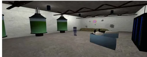
To further demonstrate the capabilities of this system, a simple game was created around the robotic character. A vir-tual environment was created, again using Blender, for the modeling and Unity for the game engine shown in Figure 7. In addition to being more visually appealing with a surrounding environment, a target was created in front of the character. The player's goal was to shoot the target using the robot's wrist
mounted laser. To do this they had to have their right arm straight and pointed directly at the target.
Figure 7. Gameplay area in Unity, as well as the character standing in the middle of the room.
To determine if this condition was met, every bone was giv-en a directional vector that pointed along the bone's lgiv-ength. This is very similar to the length vector, L, used in Equation 8. Both the forearm and upper arm start with initial direction vectors of vo = (0,0,-1,0) This vector follows from the player
starting in the attention pose, with their arms at their sides pointing straight down. At a later time the pointing vector for the forearm, vf, and upper arm, vu, can be determined by
𝑣𝑓1 = 𝑞𝑓1𝑐𝑎𝑙 𝑣𝑓0 𝑞𝑓1𝑐𝑎𝑙∗ (11)
𝑣𝑢1= 𝑞𝑢1𝑐𝑎𝑙 𝑣𝑢0 𝑞𝑢1𝑐𝑎𝑙∗ (12)
We determine if the arm is straight, with no significant bend at the elbow, by taking the dot product between vf1 and vu1.
The value of the dot product above a threshold (we use 0.95) we classify the arm as straight.
Similarly to determine if the arm is pointed at the target, the vector from the upper arm base position (the shoulder), pu, to
the target's center, pt is used. This vector vt is normalized
(Eq.12) so that the target's distance from the character is irrel-evant, since interest is solely in the direction.
𝑣𝑡=‖𝑝(𝑝𝑡𝑡−𝑝−𝑝𝑏𝑏)‖ (13)
We then take the dot product between this target vector and the pointing vector of the upper arm, though using the forearm would be equally valid. If the result is above a certain thresh-old (we used a threshthresh-old of 0.975) the arm was considered to be aiming at the target.
When both of these conditions are met, we know that the player has a straight arm and that it is pointed at the target. We then trigger the "hit" condition, which fires the player's laser, has the target explode into several pieces, and plays an ac-companying audio clip. A few seconds after the target has been destroyed a new one is generated in a random position in front of the player for them to shoot. After three successful hits the targets begin to move to increase the challenge level.
H. Oculus Rift Integration
the target due to the 1:1 motion mapping. The player was not aiming at the target on the screen, but instead was trying to judge where the target would be from the robot's perspective. This issue unintentionally increased the difficulty of hitting the target, in a way that was somewhat frustrating for the player.
To help resolve both of these issues an Oculus Rift (Devel-opment Kit 1) [47] was incorporated into the system. The Rift is a head mounted display that features both head tracking and full 3D depth perception by having a separate image presented to each eye. This device was integrated into the game project and the virtual camera was moved atop the character model to generate a first person perspective. This is why the final char-acter model in Figure 3 has no head. The geometry of the modeled head interfered with the camera view through clip-ping and obstruction issues once the camera was moved to this first-person perspective. The virtual camera was also tracked to the movements of the player's torso. This allowed any mo-tions the player made to cause the camera view move and shift the in-game perspective appropriately.
Figure 8.A user playing the game with the Oculus Rift.
While no formal testing was performed to compare the two game perspectives, it was very apparent that using the first person view made hitting the target appreciably easier and less frustrating. Players were able to point their arm at the target much more quickly and with much less adjusting when trying to find the "trigger spot". They also appeared more relaxed, moving more naturally and with their whole body rather than standing rigid while concentrating on only their shooting arm.
An additional effect of incorporating the Rift was a height-ened level of immersion within the game. Being immersed in the fully 3D virtual world with accurate head and full body (less the hands and feet) tracking added significantly to both the game itself, as well as to the perceived novelty of the body tracking. Figure 8 shows a joint image of a user playing the game with the Rift, adjacent to the in-game view.
V. LIMITATIONS AND ISSUES
There were some downsides to incorporating the Rift into the game. The entire virtual scene had to be scaled down in order to prevent the player from feeling like they were massive in size. The much closer view of the character also made the noise and jitter in the sensor more apparent. Smoothing the quaternion values between their current and previous values reduced the jitter, though it did not eliminate it entirely.
Some issues were encountered with the update rate of sen-sor information. Small stutters in the game of about half a se-cond in length occurred when the system was waiting to get a reading from a sensor. This would cause the character to mo-mentarily freeze, and even more jarringly caused pauses in the display update for the Rift. It is not entirely clear why this occurred, as the update rate of the sensors should be sufficient to avoid this. It may be that the library used to access the USB ports [48] within Unity was not well optimized to handle that many USB connections at one time, which could cause these hiccups. To help with this, the handling of reading sensor data was moved to a separate CPU thread.
VI. SUMMARY
This work presents the necessary elements required to im-plement a full body motion capture system from IMU sensors. This work improves on other work by using a 10 sensor net-work measuring the entire body as opposed to 5 sensor sys-tems that are capturing only the upper body. This allows the system to account for moving by walking in the virtual space through use of a novel anchoring system that allows the orien-tations and motion changes to be locked to a fixed foot on the ground. The wireless IMU-based sensor network holds strong potential for motion tracking applications. In particular, the system shows great promise for interacting while using head mounted displays and in mobile outdoor situations. While we did not quantitatively test the system due to time constraints, it performed well in the active game we developed and was well suited for combining with a virtual reality environment. While the drift of the sensors was an issue, this was mitigated by the development of a calibration routine. Meanwhile, the hierar-chical skeletal model allowed for controller-free navigation of the virtual world but jumping is not truly accurate. While there are still areas which could be improved, the current system as presented here is a strong functional foundation upon which to build upon in the future.
REFERENCES
[1] S. Ullah, H. Higgins, B. Braem, B. Latre, C. Blondia, I. Moerman, S. Saleem, Z. Rahman, and K. Kwak, “A comprehensive survey of wireless body area networks,” J. Med. Syst., vol. 36, no. 3, pp. 1065–1094,. 2012. [2] M. Chen, S. Gonzalez, A. Vasilakos, H. Cao, and V. C. M. Leung,
“Body Area Networks: A Survey,” Mob. Networks Appl., vol. 16, no. 2, pp. 171–193, Aug. 2011.
[3] S. Masuko and J. Hoshino, “A fitness game reflecting heart rate,” in Proceedings of the 2006 ACM SIGCHI international conference on Advances in computer entertainment technology, 2006, p. 53.
[4] G. Baradoy, “A Physiological Feedback Controlled Exercise Video Game,” University of Calgary, 2012.
[5] C. Liu, P. Agrawal, N. Sarkar, and S. Chen, “Dynamic Difficulty Adjustment in Computer Games Through Real-Time Anxiety-Based Affective Feedback,” Int. J. Hum. Comput. Interact., vol. 25, no. 6, pp. 506–529, Aug. 2009.
[6] K. M. Gilleade, A. Dix, and J. Allanson, “Affective Videogames and Modes of Affective Gaming : Assist Me , Challenge Me , Emote Me,” in Proceedings of DiGRA 2005: Changing Views–Worlds in Play, 2005. [7] R. L. Mandryk, K. M. Inkpen, and T. W. Calvert, “Using
entertainment technologies,” Behav. Inf. Technol., vol. 25, no. 2, pp. 141–158, Mar. 2006.
[8] D. Bersak, G. Mcdarby, N. Augenblick, P. Mcdarby, D. Mcdonnell, B. Mcdonald, and R. Karkun, “Intelligent Biofeedback using an Immersive Competitive Environment,” in Intelligent biofeedback using an immersive competitive environment. Paper at the Designing Ubiquitous Computing Games Workshop at UbiComp., 2001.
[9] A. Dekker and E. Champion, “Please Biofeed the Zombies: Enhancing the Gameplay and Display of a Horror Game Using Biofeedback,” in Proc. of DiGRA, 2007, pp. 550–558.
[10] L. E. Nacke, M. Kalyn, C. Lough, and R. L. Mandryk, “Biofeedback Game Design: Using Direct and Indirect Physiological Control to Enhance Game Interaction,” in Proceedings of the SIGCHI Conference on Human Factors in Computing Systems, 2011, pp. 103–112.
[11] S. I. Hjelm and C. Browall, “Brainball – using brain activity for cool competition,” in Proceedings of NordiCHI, 2000.
[12] J. A. Pineda, D. S. Silverman, A. Vankov, and J. Hestenes, “Learning to control brain rhythms: making a brain-computer interface possible,” IEEE Trans. Neural Syst. Rehabil. Eng., v. 11, no. 2, pp. 181–184, 2003. [13] G. Müller-putz, R. Scherer, and G. Pfurtscheller, “Game-like Training to
Learn Single Switch Operated Neuroprosthetic Control,” in BRAINPLAY 07 Brain- Computer Interfaces and Games Workshop at ACE (Advances in Computer Entertainment), 2007, vol. 4, p. 41. [14] A. Bashashati, M. Fatourechi, R. K. Ward, and G. E. Birch, “A survey of
signal processing algorithms in brain-computer interfaces based on electrical brain signals,” J. Neural Eng., vol. 4, no. 2, pp. 32–57, 2007. [15] K. Kuikkaniemi, T. Laitinen, M. Turpeinen, T. Saari, I. Kosunen, and N.
Ravaja, “The Influence of Implicit and Explicit Biofeedback in First-Person Shooter Games,” in Proceedings of the SIGCHI Conference on Human Factors in Computing Systems, ACM, 2010, pp. 859–868. [16] V. Shnayder, B. Chen, K. Lorincz, T. Fulford-Jones, and M. Welsh,
“Sensor networks for medical care,” ACM Press, NY, USA, 2005. [17] A. Whitehead, N. Crampton, K. Fox, and H. Johnston, “Sensor networks
as video game input devices,” in Proceedings of the 2007 conference on Future Play, 2007, pp. 38–45.
[18] G.Welch and E.Foxlin, “Motion Tracking: No Silver Bullet, but a Respectable Arsenal,” Comput. Graph. Appl., v. 22, 6, pp. 24–38, 2002. [19] A. Wood, G. Virone, T. Doan, Q. Cao, L. Selavo, Y. Wu, L. Fang, Z.
He, S. Lin, and J. Stankovic, “ALARM-NET: Wireless Sensor Networks for Assisted-Living and Residential Monitoring,” 2006.
[20] C. Lai, Y. Huang, J. H. Park, and H.-C. Chao, “Adaptive Body Posture Analysis for Elderly-Falling Detection with Multisensors,” IEEE Intell. Syst., vol. 25, no. 2, pp. 20–30, 2010.
[21] K. Kifayat, P. Fergus, S. Cooper, and M. Merabti, “Body Area Networks for Movement Analysis in Physiotherapy Treatments,” in 2010 IEEE 24th
International Conference on Advanced Information Networking and Applications Workshops, 2010, pp. 866–872.
[22] R. W. Hoyt, J. Reifman, T. S. Coster, and M. J. Buller, “Combat Medical Informatics : Present and Future Rmtr Triage,” in Proceedings of the AMIA Symposium, 2002, no. 3, pp. 335–339.
[23] R. W. Hoyt, “SPARNET – Spartan Data Network for Real-Time Physiological Status Monitoring.” 2008.
[24] A. F. Smeaton, D. Diamond, P. Kelly, K. Moran, D. Morris, N. Moyna, N. E. O’Connor, and K. Zhang, “Aggregating Multiple Body Sensors for Analysis in Sports,” in 5th International Workshop on Wearable Micro and Nanosystems for Personalised Health, 2008.
[25] S. B. Davis, M. Moar, R. Jacobs, M. Watkins, C. Riddoch, and K. Cooke, “‘Ere Be Dragons: heartfelt gaming,” Digit. Creat., vol. 17, no. 3, pp. 157–162, 2006.
[26] R. De Oliveira and N. Oliver, “TripleBeat: Enhancing Exercise Performance with Persuasion,” in Proceedings of the 10th international conference on Human computer interaction with mobile devices and services, 2008, pp. 255–264.
[27] F. Buttussi and L. Chittaro, “Smarter Phones for Healthier Lifestyles: An Adaptive Fitness Game,” Pervasive Comput. IEEE, vol. 9, no. 4, pp. 51– 57, 2010.
[28] H. Johnston and A. Whitehead, “Pose presentation for a dance-based massively multiplayer online exergame,” Entertain. Comput., vol. 2, no. 2, pp. 89–96, Jan. 2011.
[29] A. Whitehead, H. Johnston, K. Fox, N. Crampton, and J. Tuen, “Homogeneous accelerometer-based sensor networks for game interaction,” Comput. Entertain., vol. 9, no. 1, p. 1, Apr. 2011.
[30] E. Charbonneau, A. Miller, C. A. Wingrave, and J. J. LaViola Jr, “Poster: RealDance: An Exploration of 3D Spatial Interfaces for Dancing,” in IEEE Symp. on 3D User Interfaces, 2009, pp. 141–142. [31] A. Kailas, “Basic human motion tracking using a pair of gyro +
accelerometer MEMS devices,” in IEEE 14th International Conference on Health Networking, Applications and Services, 2012, pp. 298–302. [32] C. Yang, J. Hu, C. Yang, C. Wu, and N. Chu, “Dancing game by digital
textile sensor, accelerometer and gyroscope,” in 2011 IEEE International Games Innovation Conference (IGIC), 2011, pp. 121–123.
[33] C.-H. Wu, Y.-T. Chang, and Y.-C. Tseng, “Multi-screen cyber-physical video game: An integration with body-area inertial sensor networks,” in 2010 8th IEEE International Conference on Pervasive Computing and Communications (PERCOM) Workshops, 2010, pp. 832–834.
[34] K. Zintus-art, S. Saetia, V. Pongparnich, and S. Thiemjarus, “Dogsperate Escape: A demonstration of real-time BSN-based game control with e-AR sensor,” in Knowledge, Information, and Creativity Support Systems, vol. 6746, Berlin Heidelberg: Springer, 2011, pp. 253–262. [35] B. Mortazavi, K. C. Chu, X. Li, J. Tai, S. Kotekar, and M. Sarrafzadeh,
“Near- realistic motion video games with enforced activity,” in 2012 Ninth International Conference on Wearable and Implantable Body Sensor Networks, 2012, pp. 28–33.
[36] S. Kim and M.Nussbaum, “Performance evaluation of a wearable inertial motion capture system for capturing physical exposures during manual material handling tasks” Ergonomics, v56, 2, pp. 314–326, 2013. [37] E. Farella, L. Benini, B. Riccò, and A. Acquaviva, “MOCA: A
low-power, low- cost motion capture system based on integrated accelerometers,” Adv. Multimed., vol. 2007, no. 1, pp. 1–1, 2007. [38] Z.-Q. Zhang, W.-C. Wong, and J.-K. Wu, “Ubiquitous human
upper-limb motion estimation using wearable sensors.,” IEEE Trans. Inf. Technol. Biomed., vol. 15, no. 4, pp. 513–21, Jul. 2011.
[39] Z.-Q. Zhang, L.-Y. Ji, Z.-P. Huang, and J.-K. Wu, “Adaptive Information Fusion for Human Upper Limb Movement Estimation,” IEEE Trans. Syst. Man, Cybern. - Part A Syst. Humans, vol. 42, no. 5, pp. 1100–1108, Sep. 2012.
[40] H. J. Luinge and P. H. Veltink, “Measuring orientation of human body segments using miniature gyroscopes and accelerometers,” Med. Biol. Eng. Comput., vol. 43, no. 2, pp. 273–82, Mar. 2005.
[41] H. Luinge, P. Veltink, and C. Baten, “Ambulatory measurement of arm orientation,” J. Biomech., vol. 40, no. 1, pp. 78–85, Jan. 2007.
[42] C. Brigante, N. Abbate, A. Basile, A. C. Faulisi, and S. Sessa, “Towards Miniaturization of a MEMS-Based Wearable Motion Capture System,” IEEE Trans. Ind. Electron., vol. 58, no. 8, pp. 3234–3241, Aug. 2011. [43] E. R. Bachmann, “Inertial and magnetic angle tracking of limb segments
for inserting humans into sythetic environments,” Naval Postgraduate School, 2000.
[44] Xsens, “Xsens MVN,” 2014. [Online]. Available: http://www.xsens.com/products/xsens-mvn/.
[45] D. Comotti, M. Ermidoro, M. Galizzi, and A. Vitali, “Development of a wireless low-power multi-sensor network for motion tracking applications,” in 2013 IEEE International Conference on Body Sensor Networks, 2013, pp. 1–6.
[46] Unity, “Unity,” 2014. [Online]. Available: http://unity3d.com/. [47] Oculus VR, “Oculus Rift,” 2014. [Online]. Available:
http://www.oculusvr.com/rift/.