Themed Section: Science and Technology
Autonomous Pv-Array Excited Wind-Driven Induction
Generator Using Fuzzy Logic Controller For Off Grid
Application In India
Kandati Sivanarendra1, C. Naveen Kumar2
1M.Tech Student, EEE Department, SITE, Chittoor, Andhra Pradesh, India
2M.Tech, Assistant Professor, EEE Department, SITE, Chittoor, Andhra Pradesh, India
ABSTRACT
Isolated renewable energy systems that is construct completely in light of renewable resource however in the meantime solid is fundamental for taking care of the power requests of remote spots where utility grid is not accessible and for which hybrid wind-solar system assumes a urgent part. In this paper, a streamlined control conspire has been introduced for a remain solitary crossover PV array energized wind driven induction generator considering a three phase variable load with or without unbalance. The proposed plot abuses the toughness and cost induction generator as a reasonable option for a costly permanent magnet synchronous generator (PMSG) which is constantly utilized as a part of remain solitary little wind turbines. Any remain solitary system utilizes a battery, however the system is assume to convey control even without battery and the battery less method of operation is arrayed in this paper. The control plot has been approved with simulation and equipment comes about. Broad field test has been performed utilizing a 2.4 kW PV boards, 2.2 kW Wind turbine emulator and climate stations for execution assessment. The approval comes about have been introduced which demonstrates the proposed plot is required to be an appealing answer for remote application where utility grid is either not feasible or not economical.
Keywords: OFF gird, PV, wind, wind driven induction generator.
I.
INTRODUCTIONOver 400 million individuals in India, including 47.5% of those living in India‟s provincial zones, still has no entrance to power. As a result of the remoteness of quite a bit of India‟s un-jolted populace, sustainable power source can offer a financially reasonable methods for giving associations with these gatherings. There is a solid requirement for off grid power generation, to cater those divisions, where either grid augmentation is either not achievable or not savvy. Separated sustainable power source system that is construct completely in light of natural resources and in the meantime solid is vital for taking care of the power requests of remote spots where utility grid is
In any case, for any off-lattice system work, it is alluring to introduce segments and their related controls that are without boost and prudent. In this unique circumstance, Self energized induction generators utilizing capacitors have been accounted for in the writing. Squirrel Cage Induction Generator (SCIG) which is hearty, economical, require little upkeep and have higher power-weight proportion over PMSG, substantially less expensive than PMSG would be attractive decision for a remote remain solitary application. Be that as it may, regardless of these preferences, wind-driven capacitor-energized induction generators are not favored in remote power system works because of their unsuitable voltage regulation and frequency variety .However to abuse the benefits of IG and also to defeat the above downside, hybrid system utilizing a dc-dc converter fed 3-phase Voltage Source inverter (VSI) as power interface arrange, battery charged by sun oriented photograph voltaic cells (PV) and the PV energized Induction Generator (IG) driven by wind have been accounted for in the literature. The three phase Load, output of IG and output of the VSI systems a Point of Common Coupling (PCC). This hybrid scheme can work to supply the required load even without battery. However in this work, a settled resistive load has been considered for the controller configuration and additionally unbalance in load has not been considered. Further to this, hybrid scheme in view of PV and IG revealed in the writing, require an utility grid for its operation. The vast majority of them utilize a doubly encouraged induction generator, which is at the end of the day costly. It is endeavored to build up a vigorous and dependable control conspire for self-ruling hybrid system in view of PV source and wind driven induction generator that can give consistent controlled three phase output voltage for a wide range of load with or without unbalance. In the current work, an improved controller for battery less mode operation has been produced for a PV fed Boost Converter encouraged Inverter energized wind driven IG conspire (PVEWIG) to direct the inverter DC
connect without battery. In this scheme, a three phase variable resistive and additionally inductive load with or without unbalance has been considered. The proposed controller guarantees voltage regulation of DC connect and enhances the power quality parameters at purpose of normal coupling (PCC) under shifting illumination, temperature of PV array and wind speed variety in the wind generator. The proposed plot has been actualized in equipment utilizing a 2.4 kW PV cluster and a 2.25 kW Wind turbine emulator driven SCIG. This paper is sorted out as takes after. Area II depicts the power circuit topology of the PVEWIG conspire. The nitty gritty clarification of the control plot is displayed in area III. The displaying and simulation comes about are arrayed in area IV and equipment approval comes about are introduced in segment V.
II.
POWER CIRCUIT ARRANGEMENT OF THE PV ARRAY FED INVERTER EXCITED WIND DRIVENIG
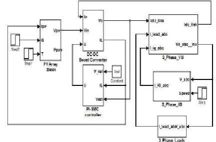
Figure 1. Block diagram of the Power Circuit for PVEWIG System with Battery
The output of the inverter goes about as a virtual grid giving a consistent voltage and recurrence. The three-phase load is associated with inverter output and is provided by PV-IG and battery or PV-IG, the load sharing being reliant on illumination and wind speed. The inverter output, IG output and load frames the purpose of normal coupling (PCC). The piece schematic of the whole PVEWIG conspire is appeared in Fig. 1. One of the exceptional elements of this half and half scheme is that, this system utilizes an induction generator without a need of either utility lattice or excitation capacitors, consequently maintaining a strategic distance from every one of the inconveniences related with it. Without battery, the real power adjust is to such an extent that the entirety of PV exhibit power and real power output of IG parallels the inverter control output which is conveyed to the load. The power adjusting is clarified in more detail in the consequent areas.
III.
CONTROL SCHEME OF THE PV ARRAY FED INVERTER EXCITED WIND DRIVEN IGIn this paper, battery less operation of the PVEWIG conspire has been considered. The system should keep on delivering power continuous amid the nonattendance of battery, which may happen either because of profound release or completely charged state of the battery. Additionally it may be important to expel the battery from the system for a concise
term for boost. In this mode, the boost converter will act in a voltage regulation mode and keeps up steady DC connect voltage under all states of climate and load changes. The Inverter is activated by an open circle sinusoidal PWM controller. The control piece chart of the dc-dc boost converter utilized as a part of this scheme is appeared in Figure 2
Figure 2. Block diagram of Cascaded PI-SMC controller for output voltage regulation of dc-dc boost
converter
output voltage control of dc-dc boost converter. The V-I attributes of PV cluster differs with light also, temperature and this moves the working purpose of the PV cluster. Further, the variety of wind speed changes the pole torque to the induction generator. These fluctuating parameters cause the contribution and in addition load of the dc-dc converter to change. In this occasion, the controller works in voltage regulation mode. The dc-interface voltage is directed utilizing a cascade PI-SMC control in which the external circle comprises of a PI controller and the internal circle comprises of a sliding mode current controller (SMC) as appeared in Fig. 2. The external PI controller creates a current reference from its information voltage blunder between reference (Vo_ref) and real output voltage (Vo) of dc-dc converter. The blunder between reference (IL_ref) and real Inductor current (IL_act) is given as contribution to SMC which creates the entryway pulse for the boost converter IGBT. The essential standard of SMC includes scheme of a sliding surface in its control law which would coordinate the regulation of the state factors towards a coveted source. Ordinarily in a solitary switch dc–dc converter, the control law that receives an switching work is
switching capacity (rationale state) of the converter‟s control switch and the state variable is the inductor current. In light of the general sliding mode control hypothesis, the state variable mistake is characterized as the distinction amongst real and reference esteem (of the inductor current), which shapes the sliding work given by l real l ref S i.
A. Inverter Control of PVEWIG conspire At the point when an IG is interfaced with the lattice or in the proposed conspire with a "PV fed DC-DC converter encouraged inverter", at first there is a colossal contrast between the initiated emf of the IG and the inverter voltage which causes a sudden inrush. The extent of this inrush relies on upon the underlying velocity of the rotor and the remaining flux of the stator of the IG. On the off chance that the rotor begins from zero speed then the size of inrush is exceptionally extreme, this is typically 5 to 6 times that of the appraised current (which is the situation of an induction motor). In this hybrid scheme, the IG is electrically incorporated with the inverter output when the speed of the IG is somewhat over the synchronous speed which relates to the cut in speed of the wind turbine. In this manner in such condition the extent what's more, span of the inrush is very little extreme and could be withstood by the information dc source of the inverter. In any case, the output voltage of the inverter Nonetheless, the output voltage of the inverter is bit by bit expanded, by gradually expanding the tweak record of the sine PWM controller to absolutely dispense with any plausibility of inrush current.
IV.
MODELING AND SIMULATION OF THE PVEWIG SYSTEMThe simulation is performed utilizing the numerical models of PV exhibit, dc-dc boost converter, induction machine, voltage source inverter (VSI) and the load keeping in mind the end goal to decrease the memory size and calculation time of the simulation,
which would somehow or another make the simulation more complex as the whole cross breed conspire with control comprises of a few subsystems. The square graph of the whole hybrid scheme utilized for simulation is appeared in Figure 3. The scientific conditions re correcting the scientific models of various subsystem appeared in figure 3 are recur rented in Table I. The PV show is communicated as given in what’s more, the dc-dc boost converter display is given by The established dq demonstrate is utilized for speaking to induction generator. The inverter conditions and load circuit are spoken to utilizing. In this scheme, the aggregate real energy of the load is shared amongst inverter and IG. The receptive energy of the load and additionally the IG is met by the inverter. The real, receptive and evident power appropriations accepting the misfortunes in the inverter and dc-dc converter are irrelevant, are given by (6) to (8)
Table 1. Mathematical Models used for recurrenting the PVEWIG system
The instantaneous current distribution at the point of common coupling (PCC) is given by (9).
The simulation piece graph of the whole hybrid plot alongside the controller executed in MATLAB/Simulink is appeared in Fig. 4. The beginning reaction of the PVEWIG system is appeared in figure 5. It could be watched the real energy of load is shared amongst inverter and IG, while the receptive energy of the load and IG is provided by the inverter. Amid beginning, the regulation file of the sine PWM inverter is step by step expanded from its underlying
zero esteem, which encourages mix of IG with the inverter without any inrush current as appeared in figure 6. The unfaltering state waveforms of voltage at PCC and current of PVEWIG system counting load, IG and inverter are appeared in figure 7. The conveyance of real power among PV exhibit and IG under unsettling influences in light, wind turbine speed and load is appeared in figure 8a. For this situation the temperature is kept up consistent at 35 deg Celsius. It can be watched the system rms voltage stays steady with the exception of a brief term unsettling influence as appeared in figure 8a. Additionally the real power adjust is guaranteed among the two sources PV exhibit and IG, giving a directed yield voltage to the load. The reaction of the system for a wind speed variety at a steady load and light is appeared in figure 8b. It can be watched, the controller guarantees the power adjust what's more, keeping up consistent DC connect voltage.
Figure 4. Simulation Block Diagram in Matlab Recurrenting the Mathematical Model of PVEWIG
System
V.
HARDWARE IMPLEMENTATION AND VALIDATIONThe proposed PVEWIG conspire is actualized utilizing a 2.4 kW PV cluster and a 2.25 kW Wind turbine emulator driven induction generator. The control conspire which involves a cascade PI-SMC control for the lift converter and open circle sine-PWM control for the inverter is actualized utilizing a Texas Instruments microcontroller TMS320F28027. Hall Impact Voltage and current sensors are utilized to detect the inverter DC connect voltage and PV exhibit current individually. The equipment piece outline of the power circuit and the control circuit are appeared in figure 9a and 9b individually. Furthermore climate Sensors including pyrometer, temperature sensors, voltage and current sensors are utilized alongside an information data logger to screen the execution of the system for a long span. The circuit parameters including evaluations of load, PV and IG utilized for equipment execution are given in Table II, which is same as the one considered for reenactment.
Figure 5. (a) Hardware Block diagram of PVEWIG system (b) Block diagram of the Power Control Unit
of PVEWIG System
The beginning grouping of battery less PVEWIG system is clarified as takes after with reference to
figure 13a. The PVEWIG system is equipped for conveying the load even without IG because of low wind speed, gave the load right then and there is inside the PV limit comparing to the illumination right then and there. This is clear from figure 13b, the load current stays unaltered even after the IG current ends up noticeably zero. The cascade PI-SMC controller manages the DC connection of the inverter in spite of climate and load unsettling influences as portrayed in figure 14a and 14b. The PVEWIG system is fit for managing unbalance in load and keeps on giving a controlled yield, which is apparent from the system reaction for lopsided resistive load and unequal resistive-inductive load appeared in figure 15a and 15b individually. The system reaction for change in wind turbine emulator (WTE) speed driving the IG alongside load change is shown in figure 16, which demonstrates the programmed modification in load share amongst PV and IG relating to change in WTE speed and load extent. Figure 17 demonstrates the regular load sharing reaction alongside the light information caught for a brief span of 10 minutes. It can be watched the system RMS voltage stays steady regardless of the adjustments in illumination, load and WTE speed.
VI.
FUZZY CONTROLLERFuzzy logic is a complex numerical strategy that permits taking care of troublesome reenacted issues with many data sources and yield factors. Fuzzy logic can give brings about the type of suggestion for a particular interim of yield state, so it is basic that this scientific strategy is entirely recognized from the more commonplace logics, for example, Boolean algebra math. This paper contains an essential diagram of the standards of fuzzy logic.
Fuzzy Logic System Today control system are generally portrayed by scientific models that take after the laws of material science, stochastic models or models which have risen up out of numerical logic. A
general trouble of such developed model is the manner by which to move from an offered issue to an appropriate scientific model. Without a doubt, today's propelled PC innovation makes it conceivable; however overseeing such system is still excessively intricate.
These unpredictable system can be streamlined by utilizing a resistance edge for a sensible measure of imprecision, dubiousness and instability amid the displaying stage. As a result, not totally idealize system comes to presence; in any case in the greater part of the cases it is fit for taking care of the issue in suitable way. Notwithstanding missing info data has officially ended up being palatable in information based system.
Fuzzy logic permits to lower many-sided quality by permitting the utilization of flawed data in sensible way. It can be actualized in equipment, programming, or a blend of both. As it were, fuzzy logic way to deal with issues' control emulates how a man would decide, just significantly quicker
The fuzzy logic examination and control strategies appeared in Figure 1 can be portrayed as:
1. Receiving one or huge number of estimations or other appraisal of conditions existing in some system that will be dissected or controlled.
2. Processing every got contribution as per human based, logic "assuming at that point" rules, which can be communicated in straightforward dialect words, and consolidated with conventional non- logic preparing.
3. Averaging and weighting the outcomes from all the individual tenets into one single yield choice or flag which chooses or guides a controlled system what to do. The outcome yield flag is an exact defuzzify esteem.
Figure 6. The fuzzy logic Control-Analysis method
To work fuzzy logic should be spoken to by numbers or portrayals. For instance, speed can be spoken to by esteem 5 m/s or by depiction "moderate". Term "moderate" can have diverse significance if utilized by various people and should be deciphered regarding the watched condition. A few esteems are anything but difficult to order, while others can be hard to decide as a result of human comprehension of various circumstances. One can state "moderate", while other can state "not quick" while depicting a similar speed. These distinctions can be recognized with help of alleged fuzzy sets.
Typically fuzzy logic control system is made from four noteworthy components displayed on Figure 2: fuzzification interface, fuzzy induction motor, fuzzy govern network and defuzzification interface. Each part alongside essential fuzzy logic operations will be portrayed in more detail underneath.
Figure 7. Fuzzy logic controller
Fuzzy Logic Basic Operations
Underneath some fundamental data about fuzzy logic will be introduced, while an exhaustive hypothesis of fuzzy logic can be found in [2].
• Universe of Discourse
It is a scope of every single conceivable esteem considered as fuzzy system input.
• Fuzzy Set
A fuzzy set µ is a capacity from the reference set X to the unit interim, i.e.
µ(X) speaks to the arrangement of every fuzzy arrangement of X.
• Membership Function
It is a graphical portrayal of fuzzy sets, µF(x).
Figure 8. A case of fuzzy logic enrollment work
Figure 8 demonstrates the enrollment elements of three fuzzy sets, "moderate", "normal", and "quick", for a fuzzy variable Velocity. The universe of talk makes every single conceivable estimation of Velocity, i.e., X = 19. For Velocity esteem 19 km/h, the fuzzy set "moderate" has the enrollment esteem 0.6. Thus, µ slow(19) = 0.6. Also, µ average (19) = 0.4, and µfast(19) = 0.
• Support The support of a fuzzy set F is the fresh arrangement of all focuses in the Universe of Discourse U to such an extent that participation capacity of F does not equivalent zero
• Crossover point It is a component in U where its participation work rises to 0.5.
• Center
The focal point of a fuzzy set F is the point (or focuses) at which µF(u) accomplishes its most extreme esteem.
Fuzzification Method
hub indicates evaluation of review of enrollment of the information variable. The main condition a participation work must meet is that it must shift in the vicinity of zero and one. The esteem zero implies that information variable is not an individual from the fuzzy set, while the esteem one implies that information variable is completely an individual from the fuzzy set.
With each info parameter there is a one of a kind enrollment work related. The participation capacities relate a weighting element with estimations of each information and the powerful principles. These weighting variables decide the level of impact or level of participation (DOM)every dynamic govern has. By figuring the intelligent result of the participation weights for every dynamic administer, an arrangement of fuzzy yield reaction extents are created. All that remaining parts is to consolidate and defuzzify these yield reactions.
Control Matrix
The rule grid is utilized to depict fuzzy sets and fuzzy administrators in type of restrictive proclamations. A solitary fuzzy if-then administer can be as per the following In the event that x is A then y is Z, Where A will be an arrangement of conditions that must be fulfilled and Z is an arrangement of results that can be deduced. In control with different parts, fuzzy administrators are utilized to consolidate more than one information: AND = min, OR = max and NOT = added substance supplement. Geometrical exhibit of fuzzy administrators is appeared in Figure 4.
Figure 9. Graphical elucidation of fuzzy administrators
The administer system is a straightforward graphical apparatus for mapping the fuzzy logic control system rules. It suits at least two info factors and communicates their sensible item (AND OR) as one yield reaction variable. The level of enrollment for run network yield can take estimation of greatest, least of the level of past of the run the show. It is frequently plausible, that after assessment of the considerable number of standards relevant to the information, we get more than one incentive for the level of enrollment. For this situation, the reproduction needs to mull over, each of the three potential outcomes, the base, the greatest or a normal of the enrollment degrees.
Derivation Mechanisms Derivation component enables mapping offered contribution to a yield utilizing fuzzy logic. It utilizes all pieces depicted in past segments: participation capacities, sensible operations and if-then guidelines. The most well-known sorts of derivation systems are Mamdani and Sugeno. They differ in methods for deciding yields.
Mamdani technique Beneath cases depend on two fuzzy control administers as
R1:if x is A1 and y is B1 then z is C1 R2: if x is A2 and y is B2 then z is C2
Result: z is C, where x measures up to x0 and y breaks even with y0. The terminating levels of the standards, indicated by αi, i = 1, 2 are ascertained by (3) (4) The individual govern yields are inferred by (5) (6)
At that point the general system yield is ascertained by oring the individual control yields (7)
At last, to get a deterministic control activity, picked defuzzification instrument must be actualized.
Sugeno strategy
Underneath cases depend on two fuzzy control leads as
Result: z0, where x measures up to x0 and y breaks even with y0.
The terminating levels of the govern are figured in an indistinguishable path from in Mamdani technique, in light of (3) and (4) conditions. The individual manage yields are figured from the beneath connections (8) (9) On the off chance that there is n governs in the lead network, the fresh control result gotten from the accompanying conditions (10)
where αi is a terminating level of the i administer, and i = 1, … ., n.
The Sugeno strategy functions admirably with straight methods, as it is computationally proficient. It is reasonable to apply enhancement and versatile strategies. Besides, it ensures coherence of the yield surface and it is appropriate to scientific examination. Leverage of theMamdani technique is that is it instinctive and has across the board of acknowledgment. It can be appropriate to human information.
Defuzzification Mechanisms
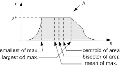
Defuzzification undertaking is to discover one single fresh esteem that compresses the fuzzy set. There are a few numerical procedures accessible: centroid, bisector, mean, most extreme, greatest and weighted normal. Figure 5 exhibit delineation of how esteems for every technique are picked.
Figure 10. Graphical show of defuzzification techniques
Centroid defuzzification is the most regularly utilized technique, as it is exceptionally precise. It gives focus of the zone under the bend of participation capacity. For complex enrollment capacities it puts levels of popularity on calculation. It can be communicated by the accompanying recipe (11) Where z0 is defuzzified yield, ui is an enrollment capacity and x is yield variable. Bisector defuzzification utilizes vertical line that partitions range under the bend into two equivalent zones. (12) Mean of greatest defuzzification technique utilizes the normal estimation of the accumulated enrollment work yields. (13) Where x' = {x; µA(x) = µ*}. Littlest of greatest defuzzification technique utilizes the base estimation of the accumulated enrollment work yields. (14)
Biggest of most extreme defuzzification strategy utilizes the greatest estimation of the amassed enrollment work yields. (15) Weighted normal defuzzification technique, in view of pinnacle estimation of each fuzzy sets, figures weighted entirety of these pinnacle esteems [4]. As indicated by these weight esteems and the level of enrollment for fuzzy yield, the fresh estimation of yield is controlled by the accompanying equation (16) Where µi is the level of participation in yield singleton i, Wi and is the fuzzy yield weight an incentive for the yield singleton.
IN OUR VENTURE WE UTILIZED THE
ACCOMPANYING RULES AND PARTICIPATION CAPACITIES:
Advantages of Fuzzy Controller over PI Controller Execution of conventional control "PI", its reaction is not all that great for non-straight system. The change is momentous when controls with Fuzzy logic are utilized, acquiring a superior dynamic reaction from the system.
Or, on the other hand
The PI controller requires exact straight numerical models, which are hard to acquire and may not giveagreeable execution under parameter varieties, stack unsettling influences, and so on. As of late, Fuzzy Logic Controllers (FLCs) have been presented in different applications and have been utilized as a part of the power gadgets field. The upsides of fuzzy logic controllers over customary PI controllers are that they needn't bother with an exact numerical model, Can work with loose information sources and Can deal with non-linearities and are more strong than ordinary PI controllers
Proposed:
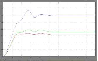
Figure 12. DC link, PV and Load RMS voltages under constant weather and load conditions
Figure 12. Inverter, Load and IG RMS currents under constant weather and load conditions
Figure 12. Load, IG and Inverter Real powers under constant weather and load conditions
Figure 12. Inverter, IG and Load reactive powers under constant weather and load conditions
Figure 13. Starting Load current under constant weather and load conditions
Figure 13. Starting Inverter current under constant weather and load conditions
Figure 13. PCC RMS Line Voltage under constant weather and load conditions
Figure 14. Steady State Voltage Inverter Voltages under constant weather and load conditions
Figure 15a. DC link, PV and Load RMS voltages under change in Irradiation and wind turbine
Speed with a constant load
Figure 15a. Load, PV and Inverter RMS currents under change in Irradiation and wind turbine Speed
with a constant load
Figure 15a. Load, IG and Inverter Real powers under change in Irradiation and wind turbine Speed with a
constant load
Figure 15a. IG speed under change in Irradiation and wind turbine Speed with a constant load
Figure 15b. Dc Link, PV and Load RMS Voltages with change in wind speed and constant load and constant
irradiation (Q=0.6 kW/Sq.mtr)
Figure 15b. IG and Inverter Real powers with change in wind speed and constant load and constant
irradiation (Q=0.6 kW/Sq.mtr)
Figure 15b. Wind Speed with change in wind speed and constant load and constant irradiation (Q=0.6
kW/Sq.mtr)
Table 1 Proposed method THD
in %
Extension method THD in %
Fig 12.13.14, 2.01% I l
Fig12.13.14 , 1.84% load I L
Fig12.13.14, 4.62% Fig 12.13.14 , 2.82%
In i n
Fig12.13.14 , 1.34% Ig
Fig 12.13.14, 1.47% Ig
Fig 15a , 1.93% Ig
Fig 15a , 1.89% Ig
Fig 15a , 1.99% il
Fig 15a, 1.89% IL
Fig 15a, 4.64% In
Fig 15a, 2.55% in
Fig 15a, 1.94% Ig
Fig 15a , 1.89% Ig
Fig 15b, 2.08% Il
Fig 15b, 2.42% Il
VII.
CONCLUSIONbattery less method of PVEWIG system. The outcomes additionally imply that the PVEWIG system with the proposed control conspire is an appealing answer for disengaged off-grid applications where utility grid is not accessible.
VIII.
REFERENCES1. O. Honorati, G. L. Bianco, F. Mezzetti, and L. Solero, “Power electronic interface for combined wind/PV isolated generating system,” in Proc. European UnionWind Energy Conf., Goteborg, Sweden, 1996, pp. 321–324.
2. B. S. Borowy and Z. M. Salameh. (1997, Mar.).Dynamic response of a stand-alone wind energy conversion system with battery energy storage to a wind gust. IEEE Trans. Energy Conversion.On line]. 12(1), pp. 73– 78. Available: DOI: 10.1109/60.577283.
3. S. Kim, C. Kim, J. Song, G. Yu, and Y. Jung, “Load sharing operation of a 14 kW photovoltaic/wind hybrid power system,” in Proc. 26th IEEE Photovoltaic Specialists Conf., 1997, pp. 1325–1328.
4. K. Kurosumi et al., “A hybrid system composed of a wind power and a photovoltaic system at NTT kume-jima radio relay station,” in Proc.20th Int. Telecommun. Energy Conf., 1998, pp. 785–789. 5. N.A Orlando,M. Liserre, R.A.A. Mastromauro.A.
(2013,July). Survey of Control Issues in PMSG-Based Small Wind-Turbine Systems. IEEE Transactions on Industrial Informatics.On line]. 9(3), pp. 211 – 1221. Available: DOI: 10.1109/TII.2013.2272888.
6. H.Shariatpanah, R. Fadaeinedjad, M. Rashidinejad. (2013,Sept.). A New Model for PMSG-Based Wind Turbine with Yaw Control. IEEE Transactions on Energy Conversion. On line]. 8(4), pp 929-937. Available: DOI: 10.1109/TEC.2013.2281814
7. Md.E.Haque,M. Negnevitsky, K.M.
Muttaqi.(2010,Nov.) A Novel Control Strategy for a Variable-Speed Wind Turbine with a Permanent-Magnet Synchronous Generator. IEEE Transactions on Industrial Applications.On line].46(1), pp.331-339. Available: DOI: 10.1109/TIA.2009.2036550
8. M. Kuschke and K. Strunz.(2014,Mar.). Energy-Efficient Dynamic Drive Control for Wind Power Conversion with PMSG: Modeling and Application of
TransferFunction Analysis. IEEE Journal of Emerging and Selected Topics in Power Electronics. On line]2(1),
pp. 35-46. Available: DOI:
10.1109/JESTPE.2013.2293632
9. S.Li, T.A. Haskew,
R.P.Swatloski,W.Gathings.(2012,May). Optimal and Direct-Current Vector Control of Direct-Driven PMSG Wind Turbines. IEEE Trans on Power Electronics.2. On line]. 7(5) pp.2325-2337. Available: DOI: 10.1109/TPEL.2011.2174254