ELECTRICAL ENGINEERING
A multi-criteria optimization technique for SSSC
based power oscillation damping controller design
Sarat Chandra Swain
a, Sidhartha Panda
b,*, Srikanta Mahapatra
aa
Department of Electrical Engineering, KIIT University, Bhubaneswar, Odisha, India
bDepartment of Electrical Engineering, VSSUT, Burla, Odisha, India
Received 13 October 2014; revised 3 March 2015; accepted 21 May 2015 Available online 16 July 2015
KEYWORDS Power system stability; Multi-criteria optimization; Pareto optimal set; Static synchronous series compensator;
Non-dominated sorting genetic algorithm-II
Abstract In this paper, Non-dominated Sorting Genetic Algorithm-II (NSGA-II) technique is applied to obtain Pareto optimal set of solutions pertaining to the tuning of lead-lag structured SSSC-based stabilizer. The design objective is to get maximum damping (performance) with mini-mum control effort (cost). Further a fuzzy based membership function value assignment method is employed to choose the best compromise solution. Simulation results are presented under various loading conditions and disturbances for various control signals to show the effectiveness and robustness of the proposed approach. The effectiveness and superiority of the proposed design approach are illustrated for both single machine infinite bus and multi-machine power systems by comparing the proposed approach with some recently published single objective and evolution-ary multi-objective approaches such as Differential Evolution (DE), Particle Swarm Optimization (PSO) and Multi-objective Genetic Algorithm. It is observed that the proposed approach yields superior damping performance compared to some recently published approaches.
2015 Faculty of Engineering, Ain Shams University. Production and hosting by Elsevier B.V. This is an open access article under the CC BY-NC-ND license (http://creativecommons.org/licenses/by-nc-nd/4.0/).
1. Introduction
Design of an optimal controller requires optimization of mul-tiple performance measures that are often non-commensurable and competing with each other. Owing to multiple and
conflicting objectives, an optimal controller that simultane-ously satisfies all objectives is usually not attainable. For example, while designing a control system, we would usually like to have a high-performance controller, but we also want to achieve desired performance with little control efforts (cost). There are two general approaches to multiple-objective optimization. One approach to solve multi-objective optimiza-tion problems is by combining the multiple objectives into a scalar cost function, ultimately making the problem single-objective prior to optimization. However, in practice, it can be very difficult to precisely and accurately select these weights as small perturbations in the weights can lead to very different solutions. Further, if the final solution found cannot be accepted as a good compromise, new runs of the optimizer on modified objective function using different weights may * Corresponding author. Tel.: +91 9438251162.
E-mail addresses: [email protected] (S.C. Swain), panda_ [email protected] (S. Panda), [email protected] (S. Mahapatra).
Peer review under responsibility of Ain Shams University.
Production and hosting by Elsevier
Ain Shams University
Ain Shams Engineering Journal
www.elsevier.com/locate/asej www.sciencedirect.com
http://dx.doi.org/10.1016/j.asej.2015.05.017
2090-44792015 Faculty of Engineering, Ain Shams University. Production and hosting by Elsevier B.V. This is an open access article under the CC BY-NC-ND license (http://creativecommons.org/licenses/by-nc-nd/4.0/).
be needed, until a suitable solution is found. This method also has the disadvantage of requiring new runs of the optimizer every time the preferences or weights of the objectives in the multi-objective function change [1]. The second general approach is to determine an entire Pareto optimal set of solu-tions or a representative subset. Pareto optimal set of solusolu-tions are often preferred to single solutions because they can be more feasible since the final solution of the decision maker is always a trade of between crucial parameters in real-life [2]. Problems of control systems involving the optimization of multiple objective functions require high computational time and effort [3]. As conventional techniques are difficult to apply, Artificial Intelligence (AI) techniques are preferred to obtain Pareto optimal set [4–6]. AI techniques such as Artificial Neural Network (ANN), Fuzzy Logic (FL) and mod-ern heuristic optimization techniques have emerged in recent years in power systems as competent tools to solve various power system problems. ANN and FL suffer from the require-ment of expert user in their design and implerequire-mentation, a lack of the formal model theory and mathematical rigors and so are vulnerable to the experts’ depth of knowledge in problem def-inition. Modern heuristic optimization techniques, by contrast, are more powerful as they exhibit a deeper comprehension of the system problems by well established models and hence have much more potential.
The presence of multiple objectives in a problem gives rise to a set of optimal solutions known as Pareto-optimal solu-tions instead of a single optimal solution. Single objective opti-mization techniques such as Genetic Algorithm (GA), Particle Swarm Optimization (PSO), Differential Evolution (DE), Simulated Annealing (SA), and Bacterial Foraging Optimization Algorithm (BFOA) suggest converting the multi-objective optimization problem to a single-objective optimization problem and provide one solution at a time. Single-objective optimization approach using weighted sum method is very time consuming and unsuitable for real-life problems. These approaches do not always guarantee a uni-formly distributed Pareto-optimal front even with equal-spaced weight vectors. On the other hand, the multi-objective evolutionary techniques produce the Pareto-optimal solutions in a single run only. Non-dominated Sorting Genetic Algorithm (NSGA) proposed by Srinivas and Deb [7]has been widely and successfully applied to solving many multi-objective problems. However, the main demerit of this approach has been its high computational complexity of non-dominated sorting, lack of elitism, and need for specifying a tunable parameter called sharing parameter. To address all the above issues Deb et al.[8]proposed an improved version of NSGA, called NSGA-II which has a better sorting algo-rithm and incorporates elitism and no sharing parameter needs to be chosen a priori.
When large power systems are interconnected by relatively weak tie lines, low frequency oscillations are observed. These oscillations may sustain and grow to cause system separation if they are not adequately damped. Recent developments in power electronics have led to the application of Flexible AC Transmission System (FACTS) controllers in power systems. FACTS controllers are capable of controlling the network con-dition in a very fast manner and this feature of FACTS can be exploited to improve the stability of power systems [9]. The Voltage Sourced Converter (VSC) based Static Synchronous Series Compensator (SSSC) provides the virtual compensation
of transmission line impedance by injecting a controllable volt-age in series with the transmission line. The ability of SSSC to operate in capacitive as well as inductive mode makes it very effective in controlling the power flow[10]. An auxiliary con-troller can be superimposed on the power flow control function of the SSSC so as to improve power system oscillation stability by damping the modal oscillations[11–13].
In [14], a SSSC-based controller employing Bacteria Foraging Optimization Algorithm (BFOA) for damping low frequency oscillations in a Single Machine Infinite Bus (SMIB) power system has been presented. The design of lead-lad controller is formulated as an optimization problem to minimize a time domain based objective function by employing BFO technique. Gravitational Search Algorithm (GSA) is employed in [15,16] to design a supplementary lead-lag structured damping controller for a SSSC for power system dynamic performance enhancement. The linear model of power system has been used for design and analysis pur-pose. A hybrid approach involving PSO and BFOA is pre-sented for the design of SSSC based damping controller in [17]where the parameters of the lead-lag structured SSSC con-troller as well as the gains of AC and DC voltage regulator are optimized. Coordinated design of SSSC with Power System Stabilizers by hybrid PSO and BFOA [18] and Improved Lozi map based Chaotic Optimization Algorithm (ILCOA) is proposed in [19]. A multi-objective GA approach is pre-sented in [20] to design the SSSC based damping controller to improve the transient performance of a power system sub-jected to a severe disturbance by minimizing the power angle, terminal voltage and power flow time trajectory deviations with respect to a post-contingency equilibrium point for a power system. In[21], NSGA-II has been applied to design a Thyristor Controlled Series Compensator (TCSC) based con-troller where the design objective was to improve the stability of the power system with minimum control effort. An Adaptive Neuro-Fuzzy Inference System (ANFIS) method based on the ANN is presented in[22]to design a SSSC based controller for the improvement of transient stability where the ANFIS structures were trained using the generated database by the fuzzy controller of the SSSC.
In view of the above, this paper investigates the application of NSGA-II technique for the tuning of lead-lag structured SSSC based power oscillation damping controller. The objec-tive of the design is to improve the damping of power system when subjected to a disturbance with minimum control effort. The research carried out in this paper aims at the following objectives:
(a) Application of multi-objective NSGA-II technique to generate Pareto set of solutions pertaining to the design of SSSC-based controller.
(b) Selection of best compromise solution by using Fuzzy based membership function value assignment technique. (c) Comparison of multi-objective NSGA-II technique and
single objective techniques such as DE and PSO. (d) Study of the dynamic performance of SSSC-based
con-troller designed using multi-objective optimization tech-nique under various operating conditions and transient disturbances.
(e) Comparison of multi-objective NSGA-II technique and Multi-objective GA (MGA) for SSSC based controller in the multi-machine power system.
2. System under study
2.1. Single-machine infinite bus power system with SSSC
In order to design the SSSC-based damping controller, as well as to assess its performance, a Single-Machine Infinite-Bus (SMIB) power system with SSSC depicted inFig. 1is consid-ered at the first instance. The system comprises a synchronous generator connected to an infinite-bus through a double circuit transmission line. The generator is equipped with Hydraulic Turbine Governor (HTG) and excitation system. The HTG represents a nonlinear hydraulic turbine model, a PID gover-nor system, and a servomotor. The excitation system consists of a voltage regulator and DC exciter, without the exciter’s sat-uration function as proposed in ‘‘IEEE Recommended Practice for Excitation System Models for Power System Stability Studies’’. In Fig. 1, T represents the transformer;
VTandVBare the generator terminal and infinite-bus voltages respectively;V1,V2andV3are the bus voltages;VDCandVcnv are the DC voltage source and output voltage of the SSSC con-verter respectively;Iis the line current andPLandPL1are the total real power flow in the transmission lines and that in one line respectively.
2.2. Modeling of Static Synchronous Series Compensator (SSSC)
A SSSC is a solid-state Voltage Sourced Converter (VSC), which generates a controllable AC voltage, and connected in series to power transmission lines in a power system. SSSC provides the virtual compensation of transmission line impe-dance by injecting the controllable voltage (Vq) in series with the transmission line.Vqis in quadrature with the line current, and emulates an inductive or a capacitive reactance so as to influence the power flow in the transmission lines. The virtual reactance inserted byVqinfluences electric power flow in the transmission lines independent of the magnitude of the line current [9]. The variation of Vqis performed by means of a VSC connected on the secondary side of a coupling trans-former. The compensation level can be controlled dynamically by changing the magnitude and polarity ofVqand the device can be operated both in capacitive and in inductive mode. The VSC uses forced commutated power electronic devices to produce an AC voltage from a DC voltage source. A capacitor connected on the DC side of the VSC acts as a DC voltage source. To keep the capacitor charged and to provide transformer and VSC losses, a small active power is drawn from the line. As presented by authors [11–14] VSC using
IGBT-based PWM inverters is used in the present study. The machine speed is determined by the machine Inertia constant and by the difference between the mechanical torque, resulting from the applied mechanical power, and the internal electro-magnetic torque and so the responses are obtained considering the inertia. Further, the gate limits are also considered in the analysis. VSC using IGBT-based Pulse Width Modulation (PWM) inverters is used in the present study. However, as details of the inverter and harmonics are not represented in power system stability studies, a GTO-based model can also be used. This type of inverter uses PWM technique to synthe-size a sinusoidal waveform from a DC voltage with a typical chopping frequency of a few kilohertz. Harmonics are canceled by connecting filters at the AC side of the VSC. This type of VSC uses a fixed DC voltage VDC. The converter voltage Vcnv is varied by changing the modulation index of the PWM modulator.
2.3. Modeling of machine
The dynamics of the stator winding, field winding, and damper windings are included in the model. All stator and rotor quantities are expressed in the two-axis reference frame (two-axisd–qframe). All rotor parameters and electrical quan-tities are referred to stator and are represented by primed variables.
The mathematical equations are given by[23] Vd¼RSidþ d dtudxRuq ð1Þ Vq¼RSiqþ d dtuqþxRud ð2Þ V0 fd¼R0fdi0fdþ d dtu 0 fd ð3Þ V0kd¼R0kdi0kdþd dtu 0 kd ð4Þ V0 kq1¼R0kq1i0kq1þ d dtu 0 kq1 ð5Þ V0kq2¼R0kq2i0kq2þd dtu 0 kq2 ð6Þ where ud¼LdidþLmdði0fdþi 0 kdÞ, uq¼LqiqþLmqþi0kq, u0 fd¼L 0 fdi 0 fdþLmdðidþi0kdÞ, u0kd¼L 0 kdi 0 kdþLmdðidþi0fdÞ,u0kq1¼ L0kq1i0kq1þLmqiq,u0kq2¼L 0 kq2i 0 kq2þLmqiq. In the above equations, the subscripts
dandqrepresentd-axis andq-axis quantities.
RandSrepresent rotor and stator quantities.
fandkrepresent field and damper windings.
landmrepresent leakage and magnetizing inductances. The mechanical equations are given by
d dtxr¼ 1 JðPeFrxrPmÞ ð7Þ d dth¼xr ð8Þ
wherexrandhare the angular velocity and angular position of the rotor respectively, Pe and Pm represent electrical and mechanical power respectively, andJandFrrepresent inertia and friction of rotor respectively.
V1 SSSC Generator Infinite-bus Tr. Line VSC Vq VDC Vcnv T V2 VT VB Bus1 Bus2 Bus3 I PL PL1 V3
3. The proposed approach
3.1. Structure of SSSC-based controller
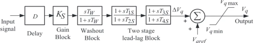
Despite significant progresses in the development of advanced control schemes over the past two decades, the conventional lead-lag (LL) structure controller as well as the classical Proportional Integral Derivative (PID) controller and its vari-ants remain the controllers of choice in many industrial appli-cations. These controller structures are preferred because of their structural simplicity, reliability, reduced dependence on skilled users and the favorable ratio between performance and cost. Moreover, the controllers offer simplified dynamic modeling and minimal developmental effort and these benefits are substantially important in engineering practice. It has been reported that the performance of lead-lag structured controller is better than a PID structured controller[24]. Therefore, the commonly used lead-lag structure shown inFig. 2 is chosen in this study as a SSSC-based damping controller to modulate the injected voltageVqfrom the SSSC. The lead-lag controller structure consists of a sensor, a gain block, a washout block, two-stage phase compensation blocks and an output limiter. The signal washout block serves as a high-pass filter, with the time constantTW, high enough to allow signals associated with oscillations in input signal to pass unchanged. From the viewpoint of the washout function, the value ofTWis not crit-ical and may be in the range of 1–20 s[25].
The phase compensation block (with time constants T1S, T2S,T3S,T4S) provides the appropriate phase-lead characteris-tics to compensate for the phase-lag between input and the output signals. InFig. 2,Vqrefrepresents the reference injected voltage as desired by the steady state power flow control loop. The steady state power flow loop acts quite slowly in practice and hence, in the present studyVqrefis assumed to be constant during the disturbance period. The desired value of compensa-tion is obtained according to the change in the SSSC injected voltageDVqwhich is added toVqref. The delay block D intro-duces the time delay when a remote signal is used.
3.2. The optimization problem
In the lead-lag structured controllers, the washout time con-stantTWis usually pre-specified[25]. A washout time constant TW= 10 s is used in the present study. The controller gainKS and the time constantsT1S,T2S,T3SandT4Sare to be deter-mined. During steady state conditionsDVqandVqrefare con-stant. During dynamic conditions the series injected voltageVq is modulated to damp system oscillations. The effectiveVqin dynamic conditions is given by
Vq¼VqrefþDVq ð9Þ
Selection of the appropriate input signal is an important issue in the design of a robust damping controller. Input signal must be able to generate correct control actions when a distur-bance occurs in the power system. Both local and remote sig-nals can be used as controllers’ input signal. To avoid additional costs associated with communication and to improve reliability, input signal should preferably be locally measurable. However, local control signals, although easy to get, may not contain the desired oscillation modes. So, com-pared to wide-area signals, they are not as highly controllable and observable. Owing to the recent advances in optical fiber communication and global positioning systems, the wide-area measurement system can realize phasor measurement syn-chronously and deliver it to the control center in real time. Synchronized time-stamped data of global positioning system are used in a wide-area monitoring system. Therefore the wide-area signal is a good option for control input. In today’s technology, dedicated communication channels should not have more than 50-ms delay for the transmission of measured signals even in the worst scenarios[11].
For local input signals, line active power, line reactive power, line current magnitude and bus voltage magnitudes are all candidates to be considered in the selection of input sig-nals for the SSSC power oscillation damping controller. Among these possible local input signals, active power and current are the most commonly employed in the literature. Similarly, generator rotor angle and speed deviation can be used as remote signals. However rotor speed seems to be a bet-ter albet-ternative as input signal for SSSC based controller[12]. In view of the above, generator speed deviation is considered as candidate input signals for the SSSC based controller. A signal transmission delay of 50 ms is considered along with the sensor time constant of 15 ms.
Tuning a controller parameter can be viewed as an opti-mization problem in multi-modal space as many settings of the controller could be yielding good performance. Modern power systems are required to operate by keeping a sufficient stability margin. High stability margin will result in underuti-lization of existing capacity whereas maximum utiunderuti-lization will make the system prone to lose stability. In view of the above, a compromise has to be made between the stability margin and system performance. In view of the above, the proposed con-troller is designed to damp power system oscillations with min-imum control effort following a disturbance. The tuning of lead-lag controller is done by optimizing the error signal and the values of the control signal simultaneously. Therefore, the objective is formulated as the minimization of functionF
given by F¼ ðF1;F2Þ ð10Þ whereF1¼ Rt1 0 e 2ðtÞdtandF 2¼ Rt1 0 u 2ðtÞdt.
S
K
W W sT sT 1 S S sT sT 2 1 1 1 S S sT sT 4 3 1 1 Input signal Gain Block Washout Block Two stage lead-lag Block Output q V qref V q V + + min q V max q V D DelayWhere ‘e’ is the error signal i.e. speed deviation (Dx), ‘u’ is the output control signal of SSSC controller andt1is the time range of simulation.
4. Nondominated shorting genetic algorithm-II
A multi-objective optimization problem differs from a single-objective optimization problem because it contains several objectives that require optimization. In case of single objective optimization problems, the best single design solution is the goal. But for multi-objective problems, with several and possi-bly conflicting objectives, there is usually no single optimal solution. Therefore, the decision maker is required to select a solution from a finite set of solutions by making compromises. A suitable solution should provide for acceptable performance over all objectives. There are two approaches to solve the multi-objective optimization problems. One approach is the classical weighted-sum approach where the objective function is formulated as a weighted sum of the objectives. But the problem lies in the correct selection of the weights or utility functions to characterize the decision-makers preferences. In the second approach, a set of solutions called the Pareto-optimal solutions are generated and the decision is taken after the optimization.
Genetic Algorithm (GA) is potentially effective in optimiza-tion problems as it has the ability to handle complex problems involving features such as discontinuities, multimodality, dis-joint feasible spaces and noisy function evaluation. Although, the conventional GA is also suitable for some kinds of multi-objective optimization problems, it is still difficult to solve those multi-objective optimization problems in which the individual objective functions are in the conflicting condi-tion. A generic single-objective GA can be easily modified to find a set of non-dominated solutions in a single run. The abil-ity of GA to simultaneously search different regions of a solu-tion space makes it possible to find a diverse set of solusolu-tions for difficult problems with non-convex, discontinuous, and multi-modal solution spaces. The crossover operator of GA exploits structures of good solutions with respect to different objectives to create new non-dominated solutions in unex-plored parts of Pareto front. In addition, most of the multi-objective approach does not require the user to prioritize, scale, or weigh objectives. Therefore, GA has been the most popular heuristic approach to multi-objective design and opti-mization problems. Pareto-based fitness assignment was first proposed by Goldberg [26] who suggested assigning equal probability of reproduction to all non-dominated individuals in the population. The method consisted of assigning rank 1 to the non-dominated individuals and removing them from contention, then finding a new set of non-dominated individu-als, ranked 2, and so forth. NSGA-II differs from a simple GA only in the way the selection operation is performed. The supe-riority of NSGA-II lies in the way multiple objectives are reduced to a single fitness measure by the creation of number of fronts which are sorted according to non-domination. Implementation of NSGA-II requires the determination of some fundamental issues. The following schemes are employed after initialization of the population in the present paper [4,6,8].
4.1. Non-dominated sorting
The initialized population is sorted based on non-domination using the following shorting algorithm:
For each individualiin the main populationMP, find the set of individualsSI, that is dominated byi.
Find the number of individuals that dominatei,Ni. For each individualjinMP, ifidominatesj, then addjto
setSI. Ifjdominatesi, increment the domination counter
Nifori.
If no individuals dominateithenibelongs to the first front; set rank of individualito one i.e.irank= 1. Update the first front set by addingito front one.
Repeat the above procedure for all the individualsiin main populationMP.
Initialize the front counterf= 1. Forkth nonempty front
Fk, the setSfor sorting the individuals for (k+ 1)th front is done. For each individualiinFk, and for each individualj inSI, domination count for individualjis decremented. If
Nj= 0 then none of the individuals in the subsequent fronts would dominatej. Hence the rank ofjis taken ask+ 1 and the setSis updated with individualj.
Increment the front counter and set S becomes the next front.
4.2. The crowding distance
The basic scheme behind the crowding distance calculation is the determination of Euclidian distance between each individ-ual in a front based on theirmobjectives in themdimensional space. All the individuals in the population are assigned a crowding distance value as the individuals are selected based on rank and crowding distance. Crowding distance is assigned front wise as explained below:
For each frontFk,iis the number of individual.
For all the individuals initialize the distance to be zero.Fk (dj) = 0, wherejcorresponds to thejth individual in front Fk.
For each objective functionm, sort the individuals in front
Fkbased on objectivem,I= sort (fk,m).
Boundary values for each individual are assigned infinite value,I(d1) =1andI(dn) =1. Forp= 2 to (n1). IðdpÞ ¼IðdpÞ þ
Iðpþ1Þ mIðp1Þ m
fmaxm fminm ð11Þ
I(p)mis the value of themth objective function of thepth individual inI.
4.3. Selection and recombination
The selection is performed using a crowded comparison oper-atoracas mentioned below:
From the crowding distanceFk(dj), the ranks are compared using the comparison operatoraci.e.pacqifprank<qrank or if p and q belong to the same front Fk then Fk(dp) >Fk(dq).
By using tournament selection with crowded comparison-operator, the individuals are selected.
Selection for individuals for next generation is performed by combining the current generation population and the off-spring population. Elitism is ensured as all the previous and current best individuals are added in the population. Based on non-domination, population is sorted and the new genera-tion is completed by each front subsequently until current pop-ulation size is obtained.
4.4. Genetic operators 4.4.1. Crossover
Simulated binary crossover scheme is employed in the present study which simulates the binary crossover observed in nature given as below:
a1;k¼ ½ð1ckÞp1;kþ ð1þckÞp2;k=2 ð12Þ
a2;k¼ ½ð1þckÞp1;kþ ð1ckÞp2;k=2 ð13Þ
where ai,k is the ith child with kth component, pi,k is the selected parent and ck is the randomly generated sample (P0) obtained from a uniformly sampled random number u
between (0, 1) defined by
pðcÞ ¼ ½ðecþ1Þcec=2; if06c61 ð14Þ
pðcÞ ¼ ½ðecþ1Þð1=cecþ2Þ=2; ifc>1 ð15Þ
cðuÞ ¼ ð2uÞ1=ðeþ1Þ ð16Þ
cðuÞ ¼1=½2ð1uÞ1=ðeþ1Þ ð17Þ
whereecis the distribution index for crossover.
4.4.2. Mutation
The polynomial mutation employed in the presented study is defined as follows: ck¼pkþ ðp u kp l kÞDk ð18Þ
where ck is the child, pk is the parent, and puk and p l k are the upper and lower bounds on the parent components respectively.
Dkis the small deviation calculated as follows: Dk¼ ð2rnÞ 1=ðemþ1Þ 1; if rn<0:5 ð19Þ Dk¼1 ½2ð1rnÞ 1=ðemþ1Þ 1; if r nP0:5 ð20Þ
where rn is an uniformly sampled random number between (0, 1) andemis the mutation distribution factor.
5. Results and discussions
5.1. Application of NSGA-II
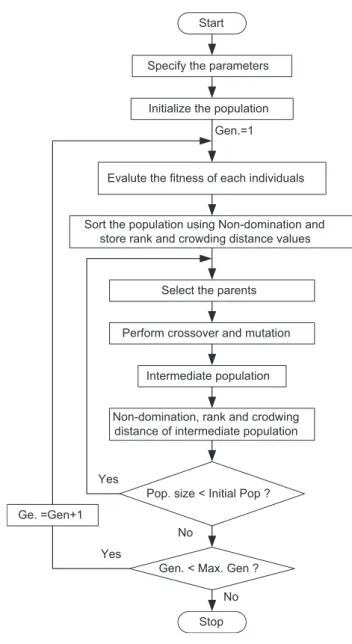
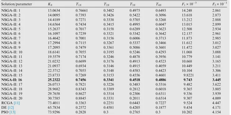
In the present study, after initializing the population the indi-viduals in the populations are sorted based on non-domination into each front. The first front being completely non-dominant set in the current population and the second front being dom-inated by the individuals in the first front only and the front goes so on. Each individual in each front is assigned rank (fit-ness) values or based on front in which they belong to. Individuals in first front are given a fitness value of 1 and indi-viduals in second are assigned fitness value as 2 and so on. In addition to fitness value a new parameter called crowding dis-tance is calculated for each individual. The crowding disdis-tance is a measure of how close an individual is to its neighbors. Large average crowding distance will result in better diversity in the population. Parents are selected from the population by using binary tournament selection based on the rank and crowding distance. An individual is selected if it has a rank value smaller than other individuals or if crowding distance is greater than the other. The selected population generates offsprings from crossover and mutation operators, which will be discussed in detail in a later section. The population with the current population and current offsprings is sorted again based on non-domination and only the best N individuals are selected, where N is the population size. The selection is based on rank and on crowding distance on the last front. The objective function given in Eq.(10) is evaluated for each individual by simulating the system dynamic model consider-ing a severe fault disturbance. The population of NSGA-II is taken as 20 individuals (real coded representation) and evolu-tionary cycle has stopping criterion of 100 generations. The flowchart of the NSGA-II algorithm used in this work is shown inFig. 3. The obtained Pareto solution set, the values of objective functions (F1 andF2) associated with the Pareto solutions and the membership function values of each solution are given inTable 1.
To show the effectiveness of the proposed NSGA-II approach for controller design, results of some recently pub-lished modern heuristic optimization methods[11–13]such as Real Coded Genetic Algorithm (RCGA), Differential Evolution (DE) and Particle Swarm Optimization for the same power system and disturbance are also provided in Table 1. The final Pareto solution surface for the 20 solutions is shown inFig. 4. It is clear fromTable 1that proposed NSGA-II tech-nique provides a set of solutions from which the user can choose the best one according to the need. It is also evident fromTable 1that when both objectives are considered, some solutions of NSGA-II are better than RCGA, DE and PSO approaches that are reported in the literature.
5.2. Best compromise solution
The ultimate aim of a multi-objective optimization algorithm is to identify a solution from the Pareto optimal set. Selection of suitable solution from all the non-inferior alterna-tives depends not only on the nature of the problem but also on the preference of the decision maker. Thus, the final solu-tion to the problem is the result of both an optimizasolu-tion
process and a decision process. Fuzzy set theory was proposed by Zadeh [27]which has been extensively applied in various fields. Fuzzy based approaches have been reported in the liter-ature to choose best compromise solution from the obtained Pareto optimal set[5,6,20,21]. In the fuzzy based approaches, various objectives are synthetically considered by marginally evaluating individual objectives and globally evaluating all objectives. The decision-makers’ preferences among the objec-tives are reflected in their global subjective evaluation, taking into consideration the various respective objectives. The best compromise solution obtained by the Fuzzy based approach is not only non-dominated but also optimal in the sense of that the decision-maker’s global subjective evaluation value is cal-culated taking into consideration the various respective objec-tives. In the present paper, a Fuzzy-based membership value assignment approach is applied to select the best compromise solution from the obtained Pareto set. Thejth objective func-tion of a solufunc-tion in a Pareto set is assigned a membership valueljdefined as[5] lj¼ 1; Jj6Jminj Jmax j Jj Jmax j J min j ; Jmin j <Jj<Jmaxj 0; JjPJmaxj 8 > > < > > : 9 > > = > > ; ð21Þ whereJmax j andJ min
j are the maximum and minimum values of thejth objective function respectively.
For each solutioni, the membership valueliis calculated as
li¼ Pn j¼1l i j Pm i¼1 Pn j¼1l i j ð22Þ wherenis the number of objective functions andmis the num-ber of solutions. The solution having a memnum-bership value close to the average membership value is chosen as the best compro-mise solution. The optimal controller parameters obtained by the above approach are shown in bold letters (NSGA-II: 16) inTable 1.
5.3. Simulation results for SMIB with SSSC
To show the robustness of the proposed design approach, dif-ferent operating conditions and contingencies are considered for the system with and without the controller. To assess the effectiveness and robustness of the proposed controller, three different operating conditions (nominal, light and heavy) are considered. Simulation studies are carried out under different fault disturbances and fault clearing sequences.
5.3.1. Nominal loading
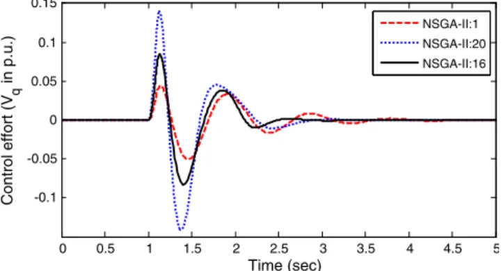
The behavior of the proposed controller is verified at nominal loading condition (Pe= 0.85 p.u.,d0= 51.5) under a severe disturbance. A 5-cycle, 3-phase fault is applied at the one end of transmission line connecting near bus 2, att= 1 s. The fault is cleared by tripping of the faulty line. The line is reclosed after 5-cycles and the original system is restored after the fault clear-ance. The time response of system error (speed deviationDw) and control effort (SSSC injected voltage Vq) are shown in Figs. 5 and 6 respectively. For comparison, three solutions are considered: two extreme solutions, NSGA-II: 1 and NSGA-II: 20 as well as the best compromise solution NSGA-II: 16, obtained by Fuzzy-based membership value assignment approach. It is clear fromFigs. 5 and 6that one solution (NSGA-II: 20) provides the best error response and another solution (NSGA-II: 1) provides the best control effort response. But when both the objectives are considered, the pro-posed solution obtained by Fuzzy-based membership value assignment approach (NSGA-II: 16) is the best compromise solution.
5.3.2. Light loading
To test the robustness of the controller under varying operat-ing conditions and location of the fault, the generator loadoperat-ing is changed to light loading condition (Pe= 0.4 p.u., d0= 22.9) and a self-clearing 5-cycle, 3-phase fault is applied at bus 3.Figs. 7 and 8show the time response of system error and control effort respectively. It is evident fromFigs. 7 and 8 that, when both the objectives are considered, the proposed solution obtained by Fuzzy-based membership value assign-ment approach (NSGA-II: 16) is the best compromise solution compared to the two extreme solutions (NSGA-II: 1 and NSGA-II: 20).
Start
Specify the parameters
Initialize the population
Evalute the fitness of each individuals
Perform crossover and mutation
Non-domination, rank and crodwing distance of intermediate population
Gen. < Max. Gen ? Gen.=1
Yes Yes
Pop. size < Initial Pop ?
No
Sort the population using Non-domination and store rank and crowding distance values
Intermediate population Select the parents
Stop Ge. =Gen+1
No
5.3.3. Heavy loading
The robustness of the proposed controllers is also tested at heavy loading condition (Pe= 1.0 p.u.,d0= 60.7). The load near bus 1 is disconnected for 200 ms (this simulates a small disturbance) and the system response is shown inFigs. 9 and 10. It is evident fromFigs. 9 and 10that, when both the objec-tives are considered, the proposed solution obtained by Fuzzy-based membership value assignment approach (NSGA-II: 16) is the best compromise solution compared to the two extreme solutions (NSGA-II: 1 and NSGA-II: 20).
5.4. Extension to Multi-Machine Power System (MMPS) with SSSC
The proposed approach of designing and optimizing the parameters of a SSSC based damping controller by multi-objective NSGA-II technique is also extended to a Multi-Machine Power System (MMPS) shown inFig. 11. It is similar Table 1 Controller parameters and objective function values with NSGA-II for SMIB system.
Solution/parameter KS T1S T2S T3S T4S F1·103 F2·101 NSGA-II: 1 13.0634 0.76661 0.3482 0.4975 0.6493 14.248 2.861 NSGA-II: 2 14.0095 0.7393 0.3426 0.5422 0.3096 13.618 2.873 NSGA-II: 3 14.4189 0.7271 0.3338 0.5705 0.3268 13.212 2.888 NSGA-II: 4 14.6564 0.7434 0.3415 0.4995 0.6047 13.015 2.899 NSGA-II: 5 15.2637 0.7017 0.3158 0.6289 0.3623 12.508 2.934 NSGA-II: 6 16.1097 0.7239 0.3321 0.5342 0.3642 12.137 2.961 NSGA-II: 7 16.4642 0.7001 0.3156 0.6006 0.3713 11.873 2.985 NSGA-II: 8 17.2994 0.7115 0.3267 0.5337 0.3466 11.612 3.012 NSGA-II: 9 17.2095 0.7479 0.3361 0.5086 0.3601 11.472 3.027 NSGA-II: 10 18.6141 0.7055 0.3195 0.5246 0.4293 11.068 3.088 NSGA-II: 11 19.5579 0.7174 0.3246 0.4878 0.3956 10.779 3.141 NSGA-II: 12 21.0232 0.6699 0.3176 0.4913 0.4523 10.668 3.165 NSGA-II: 13 21.0937 0.6934 0.3146 0.4915 0.4059 10.449 3.211 NSGA-II: 14 22.5712 0.7055 0.3148 0.4583 0.4423 10.104 3.306 NSGA-II: 15 23.8733 0.7269 0.3153 0.4556 0.4601 9.8221 3.411 NSGA-II: 16 25.2322 0.7456 0.3341 0.4518 0.4886 9.743 3.445 NSGA-II: 17 26.0713 0.7821 0.3226 0.3483 0.5316 9.482 3.622 NSGA-II: 18 28.9682 0.8343 0.3389 0.2812 0.6018 9.365 3.805 NSGA-II: 19 29.7658 0.8627 0.3314 0.2306 0.6311 9.336 3.939 NSGA-II: 20 30.7585 0.8845 0.3331 0.2011 0.6514 9.307 4.009 RCGA[11] 73.4011 0.3363 0.2251 0.6443 0.7227 9.524 4.447 DE[12] 65.7834 0.2572 0.4581 0.4205 0.1877 9.434 4.171 PSO[13] 73.9296 0.2828 0.3 0.2765 0.3 10.202 4.154 0.009 0.01 0.011 0.012 0.013 0.014 0.015 0.3 0.32 0.34 0.36 0.38 0.4 0.42 Objective F1 Objective F 2
Figure 4 Pareto solution surface with NSGA-II technique.
0 0.5 1 1.5 2 2.5 3 3.5 4 4.5 5 -0.01 -0.005 0 0.005 0.01 Time (sec) E rro r ( in p .u .) NSGA-II:1 NSGA-II:20 NSGA-II:16
Figure 5 Error response for 5-cycle, 3-phase fault disturbance in transmission line near bus 2 cleared by 5-cycle line tripping with nominal loading. 0 0.5 1 1.5 2 2.5 3 3.5 4 4.5 5 -0.2 -0.1 0 0.1 0.2 Time (sec) Control effort (V q in p.u.) NSGA-II:1 NSGA-II:20 NSGA-II:16
Figure 6 Control effort response for 5-cycle, 3-phase fault disturbance in transmission line near bus 2 cleared by 5-cycle line tripping with nominal loading.
to the power systems used in Refs.[5,11–13]. The system con-sists of three generators divided into two subsystems and that are connected through an intertie. Following a disturbance, the two subsystems swing against each other resulting in instabil-ity. To improve the stability, the line is sectionalized and a SSSC is assumed on the mid-point of the tie line. The relevant data for the system are given inAppendix A.
The frequency of the multi-mode oscillations is commonly classified in the following three main modes, local mode 0.8– 1.5 Hz, inter-area mode 0.2–1.5 Hz, and inter-plant mode 1.5–2.5 Hz[15]. The main purpose of design of an optimal con-troller should be to damp out all these three kinds of oscilla-tion modes with minimum control effort. The objective can be formulated as the minimization of multi-objective function
Fgiven by F¼ ðF1;F2;F3Þ ð23Þ where F1¼ Z t¼t1 t¼0 jDxLj tdt; F2¼ Z t¼t1 t¼0 X ðjDxIj tdtÞandF3 ¼ Z t¼t1 t¼0 jDVqj tdt:
In the above equations,DxLandDxIrepresent the local, inter-area modes of oscillations;DVqdenotes the SSSC injected volt-age i.e. the control efforts, andt1is the time range of the sim-ulation. The same approach, as explained for SMIB case, is followed to design the SSSC based controllers for the MMPS case. In this case both local signal (line active power) and remote signals (speed deviations between G1 and G3) are considered as input signal to the SSSC based controller. A time delay of 15 ms, which is introduced by the sensor, is taken into consideration for the local signals. For remote sig-nals a signal transmission delay of 50 ms is considered along with the time delay of 15 ms of the sensor. The objective func-tion given in Eq.(23)is evaluated for each of the objectives by simulating the system dynamic model considering a three-phase fault disturbance in one of the transmission lines.
The obtained Pareto solution surface for both the remote and local input signals is shown inFigs. 12 and 13respectively where the Pareto solutions are shown with the marker ‘·’ and ‘s’ respectively. The best compromise solution obtained by the above approach (NSGA-II technique and Fuzzy-based mem-bership value assignment) for both local and remote input sig-nals is given inTable 2.
In order to show the effectiveness of the proposed optimal design approach, simulation studies are carried out for the example power system under a severe disturbance. A 100 ms 3-phase fault is applied at the middle of one of the parallel transmission lines between bus 1 and bus 6 att= 1.0 s. The
0 0.5 1 1.5 2 2.5 3 3.5 4 4.5 5 -3 -2 -1 0 1 2 3 4x 10 -3 Time (sec) Error ( in p.u.) NSGA-II:1 NSGA-II:20 NSGA-II:16
Figure 7 Error response for 5-cycle self-clearing 3-phase fault near bus 3 with light loading condition.
0 0.5 1 1.5 2 2.5 3 3.5 4 4.5 5 -0.1 -0.05 0 0.05 0.1 0.15 Time (sec) Control effort (V q in p.u.) NSGA-II:1 NSGA-II:20 NSGA-II:16
Figure 8 Control effort response for 5-cycle self-clearing 3-phase fault near bus 3 with light loading condition.
0 0.5 1 1.5 2 2.5 3 3.5 4 4.5 5 -1.5 -1 -0.5 0 0.5 1 1.5 x 10⁻³ Time (sec) Error ( in p.u.) NSGA-II: 1 NSGA-II: 20 NSGA-II: 16
Figure 9 Speed error response for 200 ms load rejection near bus 3 with heavy loading.
0 0.5 1 1.5 2 2.5 3 3.5 4 4.5 5 -0.04 -0.02 0 0.02 0.04 Time (sec) Control effort (V q in p.u.) NSGA-II: 1 NSGA-II: 20 NSGA-II: 16
Figure 10 Control effort response for 200 ms load rejection near bus 3 with heavy loading.
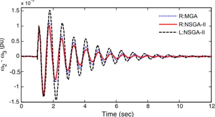
fault is cleared by tripping of the faulted line. The line is reclosed after 100 ms and the original system is restored. The system response under this severe disturbance is shown in Figs. 14–16. The plots in Figs. 14–16 correspond to the inter-area mode of oscillation, local mode of oscillation and the SSSC injected voltage respectively. In all the figures the response with remote input signal is shown with solid lines (with legend R: NSGA-II) and the response with local input signal is shown with dashed lines (with legend L: NSGA-II). For comparison, all the figures show the response with remote signal where the controller parameters are obtained using multi-objective genetic algorithm as proposed in[5], with dot-ted lines (with legend R: MGA). The system is highly oscilla-tory without control which is not shown in the figures. It can
be seen fromFigs. 14–16 that, when a remote signal is used as input to the SSSC based controller, the response with pro-posed NSGA-II optimized SSSC based controller is slightly better than the approach presented in the literature [5] for SSSC-based controller design (legend R: MGA). It can also G3 G2 SSSC G1 Bus1 Bus2 Bus3 Bus4 Bus5 Bus6 Load1 Load2 Load3 Load4 1 L 1 L 1 L 1 L 2 L 3 L T1 2 T 3 T
Figure 11 Three-machine power system with SSSC.
7 7.2 7.4 7.6 7.8 x 10⁻⁴ 1 2 3 4 x 10⁻³ 2 4 6 8 x 10⁻⁴ Fintess 1 Fitness 2 Fitness 3
Figure 12 Pareto optimal set for remote input signal.
3.7 3.8 3.9 4 4.1 x 10⁻⁴ 4 6 8 x 10⁻⁴ 6 7 8 9 10 x 10-4 Fintess 1 Fitness 2 Fitness 3
Figure 13 Pareto optimal set for local input signal.
Table 2 Best compromise solution for SSSC-based controller for multi-machine power system.
Signal/parameters KS T1S T2S T3S T4S Remote 73.5473 0.7785 0.5815 0.6231 0.7762 Local 5.81·104 0.1042 0.6811 0.5556 0.7186 0 2 4 6 8 10 12 -4 -2 0 2 4 x 10⁻³ Time (sec) 1 - 2 (pu) R:MGA R:NSGA-II L:NSGA-II
Figure 14 Inter-area mode of oscillation for 100 ms 3-ph fault cleared by line outage.
0 2 4 6 8 10 12 -1.5 -1 -0.5 0 0.5 1 1.5 x 10⁻³ Time (sec) 2 - 3 (pu) R:MGA R:NSGA-II L:NSGA-II
Figure 15 Local mode of oscillation for 100 ms 3-ph fault cleared by line outage.
be seen fromFig. 16that the control effort required to get the desired damping is very less in the proposed approach. It is also clear from the figures that the performance of the con-troller with remote signal is better compared to a local signal. To show the robustness of the proposed NSGA-II design approach, another severe disturbance is considered. A 100 ms self-clearing fault is applied at bus 4 at t= 1 s. The tie-line power flow and the SSSC injected voltage are shown in Figs. 17 and 18respectively. It is clear from these figures that the proposed controllers are robust and perform satisfac-torily with minimum control effort. Simulation results show that the performance of the NSGA-II is better than that of recently proposed MGA approach. In all cases the damping following the disturbance has improved significantly.
The power systems studied in this paper are Single Machine Infinite Bus (SMIB) and two area three machine power sys-tems. Even though, the studied multi-machine power system is a simple two-area system, the structure and parameters are realistic. The system is ideally suitable for studies related to the stability and control of local and inter-area modes, without the overwhelming complexity of actual inter-connected power systems for stability studies [5,11–14]. By studying the above simple systems, the basic characteristics of the controller can be assessed and analyzed, and conclusions can be drawn to give an insight for the implementation of SSSC in a large real-istic power system. But, for a large power system, the loca-tion/type and number of FACTS devices to be installed in the system are the major issues. Selection of input signals to the FACTS controllers and selection of objective functions are also issues of concern. Modeling of power system with hundreds of buses and a large number of generators is also
challenging. It is worthwhile to mention here that, in case of large and more complex systems, the input signal to the SSSC controller should be responsive to the mode of oscilla-tions to be damped. The input signals could be chosen from a wide range of local and global signals. The controllability and observability analysis such as Hankel singular values, right-half plane zeros, relative gain array, and minimum singu-lar value should be carried out for selecting the input signal to the controller. Also, in this example the inherent damping of the system selected was relatively low and the system becomes unstable under contingencies for a better presentation of the influence of the controller. However, in the realistic system, the damping effort contributed by the power system stabilizer may make the system stable under a contingency.
5.5. Conclusions
The significant contributions of the research work presented in this paper are as follows:
1. A multi-objective Nondominating Sorting Genetic Algorithm-II (NSGA-II) method is presented for generat-ing Pareto solution set in designgenerat-ing the SSSC-based controller.
2. A Fuzzy based approach is applied to select the best com-promise solution for the Pareto solution set.
3. Studies show that the performance of the multi-objective approach is better than that of single objective approaches when multiple conflicting objectives are to be optimized simultaneously.
4. The study is further extended to a multi-machine power sys-tem where the design objective is to improve the transient performance of a power system subjected to a severe distur-bance by damping the multi-modal oscillations with mini-mum control efforts.
5. Both local and remote signals with associated time delays are considered in the present study and a comparison has been made between the two signals.
6. The superiority of the proposed controller design approach is demonstrated under different disturbances in a multi-machine power system using both local and remote signals and the results are compared with a recently published multi-criteria design approach.
7. It is observed that the proposed controllers are robust and perform satisfactorily with minimum control effort.
0 2 4 6 8 10 12 -0.2 -0.15 -0.1 -0.05 0 0.05 0.1 0.15 0.2 Time (sec) Vq (pu) R:MGA R:NSGA-II L:NSGA-II
Figure 16 SSSC injected voltage for 100 ms 3-ph fault cleared by line outage. 0 2 4 6 8 10 12 0 500 1000 1500 2000 2500 3000 Time (sec) PL (MW) R:MGA R:NSGA-II L:NSGA-II
Figure 17 Tie-line power flow for 100 ms self-clearing 3-ph fault disturbance. 0 1 2 3 4 5 6 7 8 9 10 -0.2 -0.15 -0.1 -0.05 0 0.05 0.1 0.15 0.2 Time (sec) Vq (pu) R:MGA R:NSGA-II L:NSGA-II
Figure 18 SSSC injected voltage for 100 ms self-clearing 3-ph fault disturbance.
Appendix A
A complete list of parameters used appears in the default options of SimPowerSystems in the User’s Manual[23]. All data are in per unit unless specified otherwise.
A.1. Single-machine infinite bus power system
Generator: SB= 2100 MVA, H= 3.7 s, VB= 13.8 kV, f= 60 Hz, RS= 2.8544e3, Xd= 1.305, Xd 0 = 0.296, Xd 00 = 0.252, Xq= 0.474, Xq 0 = 0.243, Xq 00 = 0.18, Td= 1.01 s,Td 0 = 0.053 s,Tqo 00 = 0.1 s. Load at Bus2: 250 MW. Transformer: SB= 2100 MVA, V1/V2= 13.8/500 kV, 60 Hz, R1=R2= 0.002, L1= 0, L2= 0.12, D1/Yg connec-tion,Rm= 500,Lm= 500.
Transmission line: 3-ph, 60 Hz, length = 300 km each,
R1= 0.02546X/km, R0= 0.3864X/km, L1= 0.9337· 103H/km, L
0= 4.1264e3 H/km, C1= 12.74e9 F/km,
C0= 7.751e9 F/km.
Hydraulic turbine and governor: Ka= 3.33, Ta= 0.07, Gmin= 0.01, Gmax= 0.97518, Vgmin=0.1 p.u./s, Vgmax= 0.1 p.u./s, Rp= 0.05, Kp= 1.163, Ki= 0.105, Kd= 0, Td= 0.01 s,b= 0,Tw= 2.67 s.
Excitation system: TLP= 0.02 s, Ka= 200, Ta= 0.001 s, Ke= 1, Te= 0, Tb= 0, Tc= 0, Kf= 0.001, Tf= 0.1 s, Efmin= 0,Efmax= 7,Kp= 0.
A.2. Three-machine power system
Generators: SB1= 4200 MVA, SB2=SB3= 2100 MVA,
H= 3.7 s, VB= 13.8 kV, f= 60 Hz, RS= 2.8544e3, Xd= 1.305, Xd 0 = 0.296, Xd 00 = 0.252, Xq= 0.474, Xq 0 = 0.243, Xq 00 = 0.18, Td= 1.01 s, Td 0 = 0.053 s, Tqo 00 = 0.1 s.
Loads: Load 1 = 7500 MW + 1500 MVAR, Load 2 =
Load 3 = 25 MW, Load 4 = 250 MW.
Transformers:SB1= 4200 MVA,SB2=SB3= 2100 MVA,
V1/V2= 13.8/500 kV, f= 60 Hz, R1=R2= 0.002, L1= 0,
L2= 0.12,D1/Ygconnection,Rm= 500,Lm= 500.
Transmission lines: 3-ph, 60 Hz, line lengths:L1= 175 km,
L2= 50 km, L3= 100 km, R1= 0.02546X/km, R0= 0.3864X/km,L1= 0.9337e3 H/km,L0= 4.1264e3 H/km,
C1= 12.74e9 F/km,C0= 7.751e9 F/km.
SSSC: Converter rating: Snom= 100 MVA; system nomi-nal voltage:Vnom= 500 kV; frequency:f= 60 Hz; maximum rate of change of reference voltage (Vqref) = 3 p.u./s; converter impedances:R= 0.00533,L= 0.16; DC link nominal voltage:
VDC= 40 kV; DC link equivalent capacitance CDC= 375·10
6
F; injected voltage regulator gains:
KP= 0.00375, Kt= 0.1875; DC voltage regulator gains: KP= 0.1·10
3
,Kt= 20·10
3
; injected voltage magnitude limit:Vq= ±0.2.
Initial operating conditions: Machine 1:Pe1= 3480.6 MW (0.8287 p.u.);Qe1= 2577.2 MVAR (0.6136 p.u.), Machine 2:
Pe2= 1280 MW (0.6095 p.u.); Qe2= 444.27 MVAR (0.2116 p.u.), Machine 3: Pe3= 880 MW (0.419 p.u.);
Qe3= 256.33 MVAR (0.1221 p.u.).
References
[1] Coello CAC. A comprehensive survey of evolutionary-based multi-objective optimization. Knowl Inform Syst 1999;1:269–308. [2] Deb K. Multi-objective optimization using evolutionary algo-rithms. Wiley-Interscience series in systems and optimization. John Wiley & Sons; 2001.
[3] Carvalho JRH, Ferreira PAV. Multiple-criterion control: a convex programming approach. Automatica 1995;31:1025–9. [4] Panda S, Yegireddy NK. Automatic generation control of
multi-area power system using multi-objective non-dominated sorting genetic algorithm-II. Int J Electr Power Energy Syst 2013;53:54–63.
[5] Panda S. Multi-objective evolutionary algorithm for SSSC-based controller design. Electr Power Syst Res 2009;79:937–44. [6] Panda S. Multi-objective PID controller tuning for a
FACTS-based damping Stabilizer using non-dominated sorting genetic algorithm-II. Int J Electr Power Energy Syst 2011;33:1296–308. [7] Srinivas N, Deb K. Multi-objective optimization using
non-dominated sorting in genetic algorithms. IEEE Trans Evol Comput 1994;2(3):221–48.
[8] Deb K, Pratap A, Agarwal S, Meyarivan T. A fast elitist multi-objective genetic algorithm: NSGA-II. IEEE Trans Evol Comput 2002;6(2):182–97.
[9] Hingorani NG, Gyugyi L. Understanding FACTS: concepts and technology of flexible AC transmission systems. New York: IEEE Press; 2000.
[10] Gyugyi L, Schauder CD, Sen KK. Static synchronous series compensator: a solid-state approach to the series compensation of transmission lines. IEEE Trans Power Delivery 1997;12: 406–17.
[11] Panda S, Swain SC, Rautray PK, Malik RK, Panda G. Design and analysis of SSSC-based supplementary damping controller. Simul Model Pract Theory 2010;18:1199–213.
[12] Panda S. Differential evolution algorithm for SSSC-based damp-ing controller design considerdamp-ing time delay. J Franklin Inst 2011;348:1903–26.
[13] Panda S, Padhy NP, Patel RN. Power system stability improve-ment by PSO optimized SSSC-based damping controller. Electr Power Compon Syst 2008;36:468–90.
[14] Panda G, Rautraya PK. Designing of SSSC-based damping controller using bacterial foraging algorithm to improve power system stability. Int J Model Ident Control 2014;21:172–83. [15] Khadanga RK, Satapathy JK. Gravitational search algorithm for
the static synchronous series compensator based damping con-troller design. In: Proc IEEE students’ technology symposium (TechSym); 2014. p. 356–61.
[16] Panda G, Rautraya PK. Gravitational search algorithm (GSA) optimized SSSC based FACTS controller to improve power system oscillation stability. Int J Electr Electron Sci Eng 2014;8:415–22.
[17] Ali ES, Abd-Elazim SM. Optimal SSSC design for power systems via hybrid approach. Int J Electr Eng 2014;14:138–47.
[18] Panda S, Narendra KY, Mohapatra SK. Hybrid BFOA-PSO approach for coordinated design of PSS and SSSC-based controller considering time delays. Int J Electr Power Energy Syst 2013;49:221–33.
[19] Alizadeh M, Alizadeh M, Ganjefar S. Simultaneous coordinated design of PSS and SSSC using improved Lozi map based chaotic optimization algorithm (ILCOA). Neurocomputing 2013;122: 181–92.
[20] Panda S, Swain SC, Baliarsingh AK, Mohanty AK. SSSC-based controller design employing a multi-objective optimisation tech-nique. Int J Model Ident Control 2013;18:284–93.
[21] Panda S. Application of non-dominated sorting genetic algo-rithm-II technique for optimal FACTS-based controller design. J Franklin Inst 2010;347:1047–64.
[22]Khuntia SR, Panda S. ANFIS approach for SSSC controller design for the improvement of transient stability performance. Math Comput Model 2013;57:289–300.
[23] SimPowerSystems 5.2.1 User’s Guide. <http:// www.mathworks.com>.
[24]Panda S. Differential evolutionary algorithm for TCSC-based controller design. Simul Model Pract Theory 2009;17:1618–34. [25]Kundur P. Power system stability and control. New York:
McGraw-Hill; 1994.
[26]Goldberg DE. Genetic algorithms in search, optimization, and machine learning. Boston: Addison-Wesley; 1989.
[27]Zadeh LA. Fuzzy sets. Inform Control 1965;8:338–53.
Sarat Chandra Swainreceived his Ph.D. from KIIT University, Bhubaneswar in 2010, and ME from UCE Burla in 2001. Currently, he is working as an Associate Professor in the Department of Electrical Engineering, School of Technology, KIIT, University, Bhubaneswar, Orissa, India. His area of research includes optimization techniques, power system stability, FACTS and economic operation of power system.
Sidhartha Pandais working as a Professor in the Department of Electrical Engineering at Veer Surendra Sai University of Technology (VSSUT), Burla, Orissa, India. He received his Ph.D. from Indian Institute of Technology, Roorkee, India in 2008, ME in Power Systems Engineering in 2001 and BE in Electrical Engineering in 1991. Earlier, he worked as a Professor at National Institute of Science and Technology (NIST), Berhampur, Orissa and as an Associate Professor in KIIT University, Bhubaneswar, India. His areas of research include power system transient stability, power system dynamic stability, FACTS, optimization techniques, distributed generation and wind energy.
Srikanta Mahapatra is working as an Assistant Professor in the Department of Electrical Engineering, School of Technology, KIIT, University, Bhubaneswar, Orissa, India. He received his Ph.D. from KIIT University, Bhubaneswar in 2014. His area of research includes optimization techniques, power system stability.