Dynamic development of the thin-skinned thrust faulting
The dynamic development of the thin-skinned thrust faultingin the Rubjerg Knude Glaciotectonic Complex is presented as a sequence of restoration stages. Thus, thepr ogressivedeformation of thin-skinned thrust faulting and r elated syntectonic depositional devel-opments are illustrated in sequentially restored cross-sections beginning with the proximal Moserende Sec-tion and concluding with the Ulstrup SecSec-tion in the most distal partofthe thrust-fault complex. The basis of each restoration sequence is the balanced profile (Plate 2A), and the end stage is identical with the thrust-fault cr oss-section (Plate 2B), including the interpre-tationof the unexposed ramps and flats in the subsur-face.Themostproximalsections,theMårupKirkeand the Ribjerg Sections were interpr eted individually in the pr eceding chapters, and are not included here.
Ina summary scheme (see Fig. 123), it is concluded that the dynamic development was a process of con-tinuous pr ogressive deformation. Thus, although the followingdescriptionisconcentratedontheindividual sections, it should be kept in mind that there is over -lap between sections, and that the whole system was mobile. Thus a displacement of 5 m on one thrust might be followed by 10 m on a more proximal thrust and 7 m on a more distal thrust depending on the local conditions. This is the r eason why a number of displacements appear to be out-of-sequence, but with-in limits that r espect the lowest décollement level, and that displacements along the most distal, leading-edge thrusts were the last to be activated. It is ther efore also evident that displacement along a leading-edge ramp may corr espond to a translation along a flat in a proximal section.
Moserende Section
The thrust-fault development in the Moserende Sec-tion is r egarded as normal progressive piggyback thrusting from the proximal towards the distal part. The MR12 thrust sheet was probably the first to be thrust onto the r elatively thinner piggyback basin on the back of MR11 after a c. 10 m thickness of Rubjerg Knude Formation sediments had been deposited. This is included in the first stage of the sequential r estora-tion (Fig. 112, stage 1). A total of eight stages have been dif ferentiated, of which stages 1–6 are
illustrat-ed in Fig. 112. The stage precillustrat-eding the deformation is shown in Plate 2A, and the final stage terminating the deformation is reconstructed in Plate 2B.
Moserende stage 1. The initial thrusting started with 40 m displacement of MR12 over the back of what was to become MR11. This thrusting was rooted down to the 20 m intermediate décollement level. During accumulation of a 20 m thick succession of sediments in the piggyback basins above the MR13 and MR12 sheets, the thrusting progressed with ramping of MR11 over the Rubjerg Knude Formation on top of what was to become MR10. This thrusting involved ramp-ing and translation of the lower segments of MR13– MR11 from the 30 m flat level onto the 20 m flat level. The trailing-end segments of the Moserende Section were contemporaneously over-thrust by MK01, the frontal thrust of the Mårup Kirke Section, which is rooted in the 40 m décollement level. The accumulat-ed displacement of thrusting of MR13, MR12 and MR11 is estimated at about 150 m.
Moserende stage 2. Thrusting of MR09 initiated this stage. The MR09 thrusting ramped up from the 40 m décollement level, and a single duplex formed during stacking of the lower MR09 thrust segment. The MR09 sheet was displaced c. 40 m over the MR08 piggyback basin. Contemporaneously, MR10 was thrusted over MR09 and the MR10 hanging-wall flat extended from the top flat level down to the 40 m décollement level. The MR13–MR11 thrust sheets were then passively translated on the trailing lower segment of MR10.
Moserende stage 3. Initial imbrication of the MR08– MR05 thrust sheets resulted in an accumulated dis-placement of c. 200 m. The ramping was rooted in the 40 m décollement level along which the main transla-tion of the trailing-end thrust sheets of the Moser-ende Section took place. The thrusting involved a complex relationship between MR07 and MR06 that may be interpreted as a connecting splay duplex (Mi-tra & Sussman 1997). Above the L/R-unconformity, thedepositsoftheRubjergKnudeFormationpr obably reached a thickness of 20 m.
Moserende stage 4. The frontal part of the section was activated by c. 40 m translation of MR1 along the 30 m
décollement level over the lowermost trailing-end seg-ments in the Stortor n Section. MR02 and MR03 fol-lowed this translation, whereas MR04 ramped up one level from the 40 m décollement level to the 30 m flat level that resulted in the initial ramping of MR04 up over the Rubjerg Knude For mation on the back of MR03.Thecontinueddisplacement consequently re-orientated thrust sheets MR05–MR07 into more steep-ly dipping orientations. The trailing-end thrust sheets from MR08 and northwards were translated passively during this displacement.
Moserende stage 5. The frontal displacement of MR01 continued along the 20 m flat level over the trailing-end segment of the Stortorn Section. MR02 ramped up along the footwall ramp at the trailing end of MR01 during a fault-bend rotation, which also included the lower segment of MR01u. A vertical thrust separation of c. 10 m brought MR02 up along the northern termi-nation of the MR01 piggyback basin. During the pas-sage of two intermediate ramps, an irregular anticline formed on the back of MR02 that had significant im-plications for the synsedimentary structures formed in the MR02 piggyback basin (see description of the Moserende Section, above).
During MR04 thrusting, MR03 was imbricated along the upper 10 m flat level and the MR03b and MR03c thrust segments started to break through the piggy-back basin. From the rear, MR04 was pushed by MR05 which had to pass up over the fault-bend-folded seg-ment MR04u. Together with MR06 and MR07, the MR05 thrust sheet moved up to the highest level indicated by the L/R-unconformity, situated c. 20 m above sea level on the back of MR06 and MR07, and their thrust faults were steepened into a nearly vertical position.
Moserende stage 6. In the frontal part of the Moser-ende Section, MR01 picked up a lower segment and thrust up to the 20 m flat level, which consequently also elevated the piggyback basin up into its present high level. The trailing-end ramp of MR01 formed the footwall ramp for the MR02 thrusting, which resulted in a fault bend of MR02 as well as MR03. This was followed by the final displacement of 18 m along the leading MR03 thrust. Minor adjustments and re-orien-tation of MR04–MR07 followed the ramping of MR03, and the trailing-end thrust sheets MR08–MR13 were passively displaced by translation along the 40 m dé-collement level.
Moserende stage 7. During this stage, a complex du-plex was formed by thrusting of the frontal lower
seg-ments, which also including the trailing-end segments of the Stortor n Section.
Moser ende stage 8. The final displacement along the leading thrust-fault ramp in the Moser ende Section pr ogressed up along the Stortorn trailing-end foot-wall ramp. Moreover, the fault-bend folding due to thrusting in the Stortor n Section brought the thrust sheets into their present steeply dipping orientation.
Moserende Section: s
umm
ary data
Balanced length (L0): 1120 m Cross-section length (L1): 650 m Shortening (ΔL): 470 mCompression: 40.2%
Stortorn Section
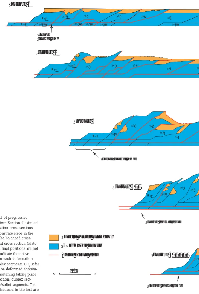
The most important development in the Stortorn Sec-tion was the change from the lowermost 40 m décol-lement level to the 30 m décoldécol-lement level. The ramp, or progr essive development of lower ramps, which marked the change, is here referr ed to as the Stortorn lower segment footwall ramp, and was located some-where near the thrust between ST04 and ST03. Thus, the ST03–ST01 thrust sheets had their lower décolle-ment level at 30 m, wher eas the thrust faults related to ST04–ST10 were rooted in the 40 m décollement level.
Formation of a duplex complex comprising the low-er most thrust segments exposed the Stortorn Forma-tion, the oldest strata involved in the thrusting. In the frontal part of the section, a complex stacking of low-er segments, r emaining in the subsurface from dis-placement in the Grønne Rende Section, resulted in duplexformationthat elevated ST01–ST03 about 30 m above the reference level. Due to arguments pr esent-ed later (see Grønne Rende Section) the duplex stack-ing had to have been contemporaneous with the short-ening of the Grønne Rende Section. In the Stortorn Section, seven stages have been differentiated of which stages 1–5 are illustrated in Fig. 113.
Stortorn stage 1. This stage is a direct continuation of the displacement in Moserende stage 4. In the Stor-torn Section, deformation was initiated by imbrica-tion of ST07, ST09 and ST10 with an accumulated dis-placement of about 50 m. This resulted in a ramping
Skærumhede Group Active thrust fault
Rubjerg Knude Formation Moserende 2 MR13 MR12 MR11 M MK1 Moserende 3 MK1 MR13 MR12 MR11 Moserende 4 MK1 MR Moserende 5 MK1 MR13 Moserende 6 MK1 100 m N S Moserende 1 MR13 MR12 MR11 MR10 MK1
Fig. 112. Dynamic model of progr essive defor-mation in the Moser ende Section illustrated in six sequential r estoration cross-sections. The six stages demonstrate steps in the development between the balanced cross-section and the structural cross-section (Plate 2); thus the starting and final positions are not shown. The red lines
indicate the active displacement surfaces in each deformation stage. The basic décollement sur face is the 40 m flat level. From this, the flat levels rise by 10 m onto the refer ence level (L/R-unconformity) defined as the 0-level. Note (1) that the final two stages (7, 8) discussed in the text are not illustrated, and (2) that the thrust-sheet terminology in Figs 112–122 is simplified (i.e. MR3 on Fig. 112 is equivalent to MR03 in the text).
Stortorn footwall ramp Stortorn footwall ramp Stortorn footwall ramp MR10 MR9 MR8 MR7 MR6 MR5 MR4 MR1 ST10 MR10 MR9 MR8 MR7 MR6 MR5 MR1 ST10 MR1 ST10 R13 MR12 MR11 MR10 MR9 MR8 MR7 MR6 MR5 MR4 MR3 MR2 Stortorn footwall ramps 3 MR12 MR11 MR10 MR9 MR8 MR7 MR6 MR5 MR4 MR4u MR3a MR3u MR3c MR3b MR2 MR1a MR1u MR1 ST10 ST10 MR13 MR12 MR11 MR10 MR7 MR6 MR5 MR4 MR3c MR3b MR3a MR2 MR1 ST10 ST10u ST10u MR8 MR9 Stortorn footwall ramp MR9 MR8 MR1 ST10
100 m
N S
Skærumhede Group Active thrust fault
Rubjerg Knude Formation
MR1 ST10 ST9 ST8 ST7 ST6 Stortorn 2 ST5 MR1 MR1 ST10u ST10 ST9 ST8 ST7 ST6 ST5u ST8u ST8u ST9u Stortorn 1 Stortorn footwall ramp ST10 MR1 ST9 ST6 ST7 ST8 Stortorn 4
Stortorn footwall ramps
Stortorn 5
Stortorn footwall ramps
ST10 MR1 ST10
ST9 ST8
Stortorn 3
Stortorn footwall ramps
Fig. 113. Dynamic model of progr essive deformation in the Stortorn Section illustrated in five sequential restoration cr oss-sections. The cross-sections demonstrate steps in the development between the balanced cross-section and the structural cross-cross-section (Plate 2); thus the starting and final positions are not shown. The red lines indicate the active displacement sur faces in each deformation stage. Note that the duplex segments GRu refer to elements that had to be defor med contem-poraneously with the shortening taking place in the Grønne Rende Section; duplex seg-ments STs refer to horse/splint segments. The final two stages (6, 7) discussed in the text ar e not illustrated.
ST4 ST2 ST1 ST1s RF6 ST3 ST4 ST4s ST4s ST4s ST4s ST2s ST1s
Stortorn lower ramp
Rubjerg Knude Fyr ramp frontal footwall ramp
ST5
ST5
ST4 ST3 ST2
Rubjerg Knude Fyr footwall ramp Rubjerg Knude Fyr
footwall ramp
Stortorn lower segment footwall ramps
Rubjerg Knude Fyr footwall ramp Stortorn lower segment footwall ramps
ST9 ST7 ST6 ST5 ST4 ST3 ST2 ST1 RF6 GRu GRu GRu ST8 ST6 ST5 ST4 ST3 ST2 ST1 ST2s RF6
Stortorn lower footwall ramp
RF6 ST1s
ST1
up of ST10 from décollement level 40 m to flat level 30 m, along which the translation displacement took place. Most of the ST09 thrust sheet was also ramped up by the for mation of a lower duplex structure. Both ST10 and ST09 wer e affected by fault-bend folding, whichcreatedamajordistortion of the L/R-unconform-ity surface in the upper most part of the thrust sheets.
Stortorn stage 2. During an accumulated displacement of about 200 m r elated to the ST10 and ST09 thrusts, ramping pr ogressed with development of the first imbrications of ST08 and ST06. Due to ramping from the lowest décollement level to the 30 m flat level in the trailing end of ST06, a fault bend affected the ST07– ST10 thrust sheets that were translated piggyback on the ST06 thrust sheet. This contributed to the steep-ening up of the ST07–ST10 thrust structur es.
In the frontal part of the section, the imbricate thrust-ing was initiated at ST01–ST03. Accumulation of sedi-ments r eferr ed to the Rubjerg Knude For mation reached a maximum thickness of about 20 m, notably in the synfor mal troughs of ST03 and ST09 that for med during the pr ogress over the ramps below.
Stortorn stage 3. At this stage, ST05 was thrust about 40 m up over the footwall ramp on the back of ST04. The ST05 thrust was rooted in the 30 m flat level, and during a passage of a lower ramp from flat level 30 m to 20 m, the initial fault-bend-fold resulted in undula-tion of the L/R-unconfor mity at the top of the ST05 thrust sheet. The ST06 thrust sheet progressed over the footwall flat of ST05, and both thrust faults wer e rooted down to the 30 m flat level along which the main translation of the sheets emplaced piggyback on ST06 took place. The ST08 thrust sheet was finally displaced along the upper flat at the top of the ST07 piggyback basin. Consequently, most of the 20 m thick succession in this piggyback basin was pr eserved and indicates the maximum level of sediment accumula-tion in the Rubjerg Knude Formaaccumula-tion during stage 3. Thrusting of the ST08 sheet along the footwall ramp onthebackof ST07 resulted in a further steepening of ST09 and ST10, while the frontal elevated parts of the ST08–ST09 thrust sheets became subject to erosion.
The trailing-end lower segments of ST10–ST07 were over-thrust by the fr ontal parts of MR01 and MR02, corr esponding to stage 7 in the Moserende Section. The accumulated displacement in Stortor n stage 3 was of the order of 320 m.
Stortor n stage 4. During this stage, the ST04 thrust
sheet was thrust 40 m over the piggyback basin of ST03, and ST05 was thrust about 70 m over the upper flat on top of the piggyback basin of ST04. During this relatively large displacement of ST05, two lower duplex segments were picked up from the lower 40 m décollement level. After ramping over the Stortorn lower ramp, the duplex segments participated in the thrusting up along the footwall ramp on the back of ST04.
The lower trailing-end segments of the Stortor n Section were finally thrust up along the steep foot-wall ramp on the back of ST10 and subsequently the frontal parts of the Moser ende Section were brought into their present upright orientation. Erosion and re-deposition affected the piggyback basins on ST05 and ST08, whereas thrusting over ST07 and ST04 sealed these piggyback basins. The accumulated displace-ment reached about 410 m.
Stortorn stage 5. A substantial displacement, in the order of 80 m, took place along the leading thrust in the Stortorn Section at this relatively late stage of de-velopment of the structures at Stortor n. However, this is only a small amount of the accumulated displace-ment (c. 500 m) which is of the same order of magni-tude as that taken up by the duplex stacking of the lower trailing-end segments of the Rubjerg Knude Fyr and Grønne Rende Sections. The ramping and thrust-ing of ST01–ST04 over this duplex structure explains the high elevation of the L/R-unconformity and over-lying piggyback basins in the frontal part of the Stor-torn Section. The formation of the duplex stack com-prising the lower duplex segments annotated GRu in Fig. 113 would have taken place only after the imbri-cate thrusting in the Grønne Rende Section developed (see below). The combination of displacement at the leading edge in one section and stacking of lower duplex segments in another, indicates a continuous progressive thrust-fault evolution.
During the propagation of ST05, the trailing end of ST04 was involved in a duplex formation that result-ed in fault-bend folding of the earlier formresult-ed ST05 lower duplex at the Stortorn lower ramp. The piggy-back basin on the piggy-back of the ST05 thrust sheet was deformed into a north-verging syncline due to steep-ening. A similar re-orientation is seen in the thrust-isolated piggyback basins in ST10 and ST09.
A marked diapirism and r emobilisation of mud in the ST01–ST03, ST05–ST07 and ST09 thrust sheets sug-gests that the diapirism was related to the intensity of ramping, especially when the ramping involved the
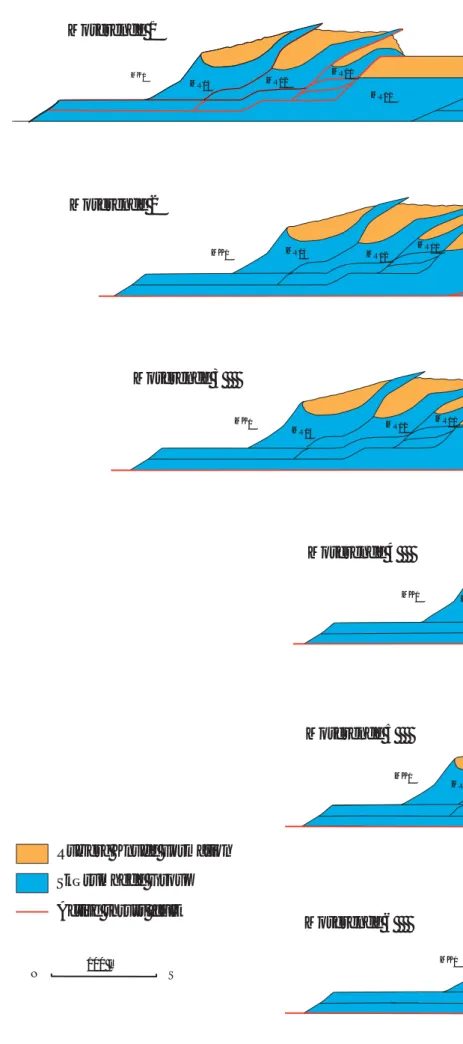
Fig. 114. Dynamic model of progr essive deformation in the Rubjerg Knude Fyr Section illustrated in four sequential r estoration cross-sections. The cross-sections demonstrate five stages in the development between the balanced cross-section and the structural cross-section (Plate 2). The red lines indicate the active displacement surfaces in each deformation stage. Note that the tip of the RF04 thrust sheet was displaced by normal faulting during syntectonic deposition in the RF03/RF04 piggyback basin.
lower level segments and fault-bend folding of these segments.
Stortorn stage 6. The final ramping of lower segments from décollement level 40 m to flat level 30 m at the base of ST05 terminated the translation along the low-er most 40 m décollement level. For the sections
fur-ther south, the lower décollement level was situated at the 30 m level. In the frontal part of the section, continued minor compr ession steepened the thrust structures, and the tips of ST02 and ST03 were er oded and deposited in the piggyback basin of ST01.
ST01 thrust sheet and the underlying duplex struc-ture, became fault-bend-folded during the thrust pr op-agation related to the progressive defor mation in the Rubjerg Knude Fyr Section.
Stortorn Section: s
umm
ary data
Balanced length (L0): 1125 m Cross-section length (L1): 570 m Shortening (ΔL): 555 mCompression: 49.3%
Rubjerg Knude Fyr Section
The Rubjerg Knude Fyr Section roots into the 30 m décollement level. The most striking features devel-oped in the Rubjerg Knude Fyr Section are the large olistoliths in the piggyback basin that were derived from the collapse and gravity gliding of a projecting segment of ST04. Five stages in dynamic development have been distinguished, which are illustrated by four cross-sections in Fig. 114.
Rubjer g Knude Fyr stage 1. During sedimentation of thefirst10m of sand of the Rubjerg Knude For ma-tion, the RF05, RF04 and RF03 thrust sheets wer e thrust up along their footwall ramps. RF04 was displaced 90 m along the upper flat level (10 m level) befor e the fr ontalpartpropagatedupalongtheupperramp.With adisplacement of about 30 m, this brought the nose of the RF04 thrust sheet up into the open air, above the sedimentation level of the Rubjerg Knude Forma-tion. Thedisplacementontheothertwothrusts amount-edtoc.20m,implyinganaccumulateddisplacement of70 m.
Rubjer g Knude Fyr stage 2. The exposed nose of the RF04 thrust sheet slumped down along a nor mal fault into the piggyback basin of RF03. At the same time, the frontal nose of RF03 was eroded away and sedi-mentation of the Rubjerg Knude Formation onlapped and covered these features. At the leading edge of the section, thrusting was initiated that brought RF01 and RF02 up over what was to become the trailing-end segments of the Grønne Rtrailing-ende Section.
Rubjer g Knude Fyr stage 3. The fr ontal imbrication of RF01 and RF02 pr ogressed during sedimentation up to about 20 m above the main L/R-unconformity
lev-el. The RF05–RF06 thrust sheet ramped up onto the intermediate flat above the trailing-end segment of RF04. The RF04 thrust sheet was displaced about 70 m up along the relatively steep footwall ramp at the trailing end of RF03. Due to the fault-bend folding of RF04, the RF05–RF06 hanging-wall ramp was rotated into a vertical position.
Rubjerg Knude Fyr stage 4. When the second ‘drop’ of the frontal part of thrust sheet RF04 took place, a c. 45 m long slab of the relatively thin thrust-sheet nose slumped down along a normal fault with a vertical separation of more than 10 m. The ‘drops’ may be regarded as two break-back sequences of the RF04 thrust sheet (in the terminology used by Mitra & Suss-man 1997; see Figs 99, 100). Sediment accumulation continued in the piggyback basin to a thickness of more than 30 m, including the ‘dropped’ noses of RF04. The final accumulation in the piggyback basin took place while the displacement in the Rubjerg Knude Fyr Section was concluded more than 500 m laterally to the south. The translation progressed along the 20 m flat level on top of what was to become the lower trailing-end segments of the Grønne Rende Section.
Rubjerg Knude Fyr stage 5. The continued displace-ment of RF04 resulted in structural propagation of this sheet above its own piggyback basin with the ‘dropped’ thrust noses. Stage 5 in the Rubjerg Knude Fyr Section is interpreted to have been contempora-neous with stage 7 in the Stortorn Section in which compression brought the thrust sheets into their final, steeply inclined position.
R
u
bjerg Kn
u
de Fyr Section: s
umm
ary data
Balanced length (L0): 525 m
Cross-section length (L1): 260 m Shortening (ΔL): 265 m
Compression: 50.5%
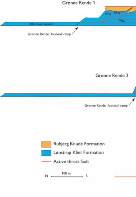
Grønne Rende Section
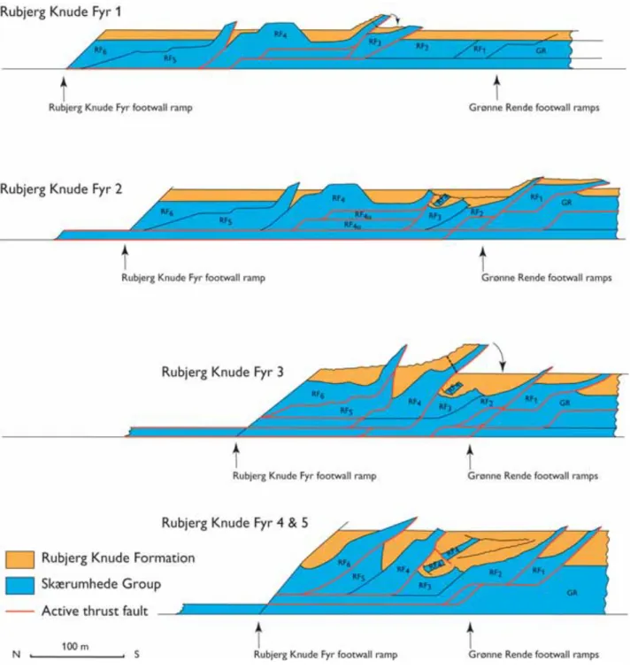
The impressive imbricate fan composed of 12 upright thin thrust sheets is the essential element in the Grønne Rende Section. As a consequence of the displacement in the imbricate fan, 550 m of trailing-end lower seg-ments were left behind to be stacked in a duplex be-low the frontal part of the Stortor n Section (Fig. 113).
Four stages have been differentiated in the develop-ment of the Grønne Rende Section, the first three of which are illustrated in Fig. 115.
Grønne Rende stage 1. The initial thrust-fault frame-work was a low-angle imbrication, about 20° on each upper hanging-wall ramp, which rooted down to the upper 10 m flat level. During thrusting, the upper thrust sheets were split up into three main segments with leading thrust faults below GR02, GR06 and GR11/ GR12 which ramped down to the main level of de-tachment in the 20 m flat level. The initial displace-mentofthe imbricatefanisregardedtohavebeen20m on each thrust. This implies that the accumulated dis-placement sums up to 240 m. GR01 was not affected by thrusting in the first stage, and 240 m of its lower trailing-end segment was consequently not displaced during this stage.
The sediments of the Rubjerg Knude Formation at-tained a maximum thickness of 15 to 20 m during this stage, with decreased thicknesses on the back of the GR06–GR08 thrust sheets, which were elevated to the highest position.
Grønne Rende stage 2. The imbricate thrusting pro-gressed with a displacement of 50 m on each thrust. This implies that the hanging-wall flats were fault-bend-folded while they passed the footwall ramps, result-ing in a dramatic steepenresult-ing of the thrust sheets. Be-low GR10–GR12, the GR07u and GR08u Be-lower seg-ments formed a duplex structure that resulted in ele-vation and complex ramp-propagation folding of the sheets above. The accumulated displacement implies an increase in length of the trailing-end segment of GR01 in the order of 500 m, allowing for some adjust-ments due to the irregular duplex deformation. Sedi-ment thicknesses in the piggyback basin in the front-al part of the section increased to 25–30 m.
Grønne Rende stage 3. Finally, the leading-edge thrust was activated and GR01 was displaced 50 m up along its footwall ramp. The GR01 thrust roots in the lower 30 m décollement level, and the displacement of the hanging-wall flat up along the footwall ramp resulted in steepening of all the early-formed thrust elements (GR02–GR13).
The displacements of the individual thrust sheets range between 60 and 70 m. The thrusting resulted in the final, almost vertical, orientation of the thrust sheets. In the rear part of the section, complex defor-mation of the duplex below GR10–GR13 was
reflect-ed in unusual folding of the breflect-eds in the GR13 thrust sheet where folds with horizontal axial planes were formed due to gravity collapse of the piggyback ba-sins.
Grønne Rende stage 4. This stage concluded the thrust-ing of the leadthrust-ing hangthrust-ing-wall ramp-and-flat over the footwall ramp in the trailing end of the Stenstue Rende Section and the subsequent final rotation of the GR02– GR05 thrust sheets. In the trailing end of the section, the RF01 and RF02 sheets concluded the displacement by thrusting from the trailing-end segments of GR12 up over the footwall ramp onto the back of GR13. Moreover, GR13 was rotated into an upright position whereby the horizontal axial planes became vertically orientated (Plate 1).
Grønne Rende Section: s
umm
ary data
Balanced length (L0): 1080 m Cross-section length (L1): 423 m Shortening (ΔL): 657 mCompression: 60.8%
Comment. The lengths are measured from the foot-wall ramp between RF01 and GR13 to the footfoot-wall ramp between GR01 and SS06, near the thrust trunca-tion of the L/R-unconformity.
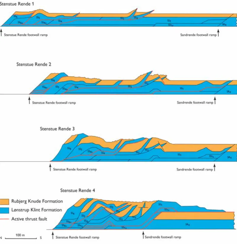
Stenstue Rende Section
Two markedly different structural complexes wer e formed during the development of the Stenstue Rende Section. They were mainly caused by the displace-ment of the same thrust sheet (SS01) when it was dis-placed 200 m over the upper flat on top of the piggy-back basin in the Sandrende Section. The frontal part of SS01 above the footwall flat of the SR04 thrust sheet is one of the complexes. The other structural com-plex is the chaotic breccia and gravity slumping in the northern part of the section that for med as the piggy-back thrust sheets were transported over a minor an-tiformal stack in the central lower part of the section. The progressive dynamic development in the Sten-stue Rende Section is described in ter ms of five stages, the first four of which ar e illustrated in Fig. 116.
Stenstue Rende stage 1. Four minor imbrications with an accumulated displacement of 70 m initiated the
development in the Stenstue Rende Section. At the leading-edge thrust, a minor connection splay sepa-rated SS02 and SS03. Most of the thrusting was locat-ed at the upper 10 m flat level for a distance of about 180 m, in the northern part of which it was eventually rooted down to the lower décollement level. The dis-placement of the SS05 thrust sheet followed the same system, but with a smaller translation along the upper 10 m flat level. At the trailing end, SS06 was thrust up along a steep footwall ramp, and her e the formation of duplex structur es was probably initiated. The thick-ness of sediment (Rubjerg Knude Formation) that had accumulated by this stage amounted to 10 m.
Stenstue Rende stage 2. The leading-edge thrusting shifted to the SS01 thrust sheet, which was displaced 20 m up along the footwall ramp (the trailing end of SR04 in the Sandrende Section). The SS01 thrust fault extended down via an intermediate ramp to the 20 m flat level, and about 200 m from the leading footwall ramp it stepped down the lower ramp to the 30 m décollement level. At the upper hinge of the lower ramp, SS01 was folded into a fault-bend anticline, a small detachment anticline. Along the foreland-dip-ping limb of the anticline in the SS01 thrust sheet, a normal fault was formed that displaced the tip of the SS02 thrust sheet. Furthermore, the SS03 thrust sheet
Fig. 115. Dynamic model of progr essive deformation in the Grønne Rende Section illustrated in thr ee sequential restoration cross-sections; the final stage (4) described in the text is not illustrated. The red lines
indicate the active displacement surfaces in each deformation stage. Note how the shortening due to the displacement along the 20 m flat level r esulted in the substan-tial length of the ‘left over’ lower duplex segment between the 20 and 30 m flat level.
became steeply inclined, and the initial imbrication of the thin SS03 thrust sheet resulted in the separation of SS03 from SS04.
In the trailing end of the Stenstue Rende Section, duplex stacking of the lower segments in SS06 result-ed in elevation of the L/R-unconformity more than 10 m above the mean level. The accumulated displace-ment ranged up to 160 m.
Stenstue Rende stage 3. Thrusting of SS04 progr essed on the upper flat over the piggyback basin of SS03 with a frontal displacement of 80 m. The hanging-wall flat of SS04 ramped up along the foothanging-wall ramp
of SS03 and during this translation the nose of SS05 became fault-bend-folded into a syncline with a steeply dipping southern limb. The trailing end of the SS04 thrust sheet was translated along the 10 m flat level; it was pushed fr om the rear by the ramping of the trail-ing end of the SS05 thrust sheet whereby the SS06 thrust sheet also steepened up. Sediment thicknesses in the piggyback basins incr eased to c. 20 m, and the accumulated displacement ranged up to 240 m.
Stenstue Rende stage 4. The dramatic major foreland thrusting of the SS01 thrust sheet, which included about 200 m displacement of the hanging-wall ramp
Fig. 116. Dynamic model of pr ogressive deformation in the Stenstue Rende Section illustrated in four sequential restoration cr oss-sections; the final stage (5) described in the text is not illustrated. The cross-sections demonstrate the development stages between the initial and final positions displayed in the balanced and the structural cr oss-sections in Plate 2. The r ed lines indicate the active displacement sur faces in each deformation stage.
over the piggyback basin of the Sandrende Section, occurred contemporaneously with the formation of anantiformalstackabovethe trailing end of SS01. The creation of the antiformal stack had already been initia-ted by the earlier formation of the minor detachment anticline at the ramp splitting the lower segments of SS01 (the SS01u segments). A duplex duplication of the lower SS01u segments accentuated the anticline, and finally the SS03 thrust sheet riding piggyback on SS01 was folded into an anticline with a steep fore-land-dipping southern limb (Fig. 90). Along this limb, a normal fault developed that displaced the fr ontal part of the SS04 thrust sheet. A chaotic soft sedimen-tary fault breccia was for med during the stretching and fault separation of SS04 (Fig. 91). Due to an extra push from the rear, the SS05 thrust sheet was displaced a further 30 m to the south, which resulted in the formation of a huge southerly overtur ned slump fold above the normal fault zone (Fig. 89).
The accumulated displacement totals about 470 m. The displacement of the SS01 hanging-wall flat up along the steeply dipping footwall ramp constrains the sequential thrusting of the Stenstue Rende rela-tive to the Sandrende thrusting. Thus stage 4 could not have begun before the maximum sedimentation in the piggyback basin was accomplished in the Sand-rende Section. The initial SS01 thrusting could be re-garded as a growth fault, wher eby the syntectonic accumulation of sand added to the steepening of the footwall ramp. The present vertical to northerly over-turned orientation of the SS01 hanging-wall flat and ramp resulted from differential thrusting and fault-bend of the SS01u lower hanging-wall ramp. Note also the re-orientation of the normal fault at the tip of SS02, which due to the same deformation was bent into a horizontal position.
Stenstue Rende stage 5. This stage corresponds to stage 6 in the Sandrende Section, wherein the SS01 thrust sheet riding piggyback on SR04 was displaced by normal faulting (Fig. 117, stage 6).
Stenst
u
e Rende Section: s
umm
ary data
Balanced length (L0): 760 m
Cross-section length (L1): 285 m Shortening (ΔL): 485 m
Compression: 62.5%
Comment. The lengths are measured fr om the
foot-wall ramp between GR01 and SS06 to the footfoot-wall ramp between SS01 and SR04. If the compression was calculated from the leading-edge thrust tip of SS01 to the trailing-end footwall ramp of SS06, L1 amounts to 455 m, ΔL = 305 m and the calculated compression would only be 40.1%.
Sandrende Section
The dynamic development of the Sandrende Section was formerly interpreted as a combination of diapir-ism and normal faulting caused by volume exchange during thrust propagation (Sadolin et al.1997). The model presented here aims at an explanation of the development purely based on a thin-skinned thrust-fault model including dif ferential ramping and duplex formation. Thus, the diapirism is interpr eted to be an effect of ramping and fault-bend folding gr owth, sim-ilar to the model of Mitra & Sussman (1997), but also including mud-mobilisation and exaggeration of back-limb thrusting. The normal faulting occurring in the Sandr ende Section is interpreted as the effect of dif-ferential ramping of a lower trailing-end segment that created foreland-dipping features above a hanging-wall ramp propagation along an intermediate foot-wall flat. Six stages of dynamic development have been dif ferentiated in the Sandrende Section (Fig. 117).
Sandr ende stage 1. After initial deposition of a 3–5 m thick succession of Rubjerg Knude Formation sedi-ments, the SR04 thrust sheet started thrusting about 50 m over the upper flat. The dip of the footwall ramp was r elatively gentle, only c. 14°, and in the 15 m flat levelthethrustfaultmay betracedalongaminorflat segment on top of the lower trailing-end segment of SR03 (SR03u). Fr om the minor intermediate flat, the thrust fault rooted down to the 30 m décollement lev-el along a 20° dipping footwall ramp of SR03u. Note that an upper and lower SR04 hanging-wall ramp was introduced subsequently.
Sandrende stage 2. Translation of the lower SR04 hang-ing-wall ramp along the intermediate flat established the anticline in the central part of the SR04 thrust sheet. The SR03 thrust sheet started to propagate towards its foreland along the upper 10 m hanging-wall flat, and the frontal part of SR03 was displaced 50 m over the upper flat on top of the piggyback basin of SR02. The tip of the SR02 thrust sheet propagated up along a growth-fault ramp, which caused the steeply dipping
orientation of the northern boundary of the piggy-backbasinatthetopoftheSR01thrustsheet.The accu-mulated displacement ranged up to about 150 m, in-cluding the initial thrusting of SR01.
Sandrende stage 3. During stage 3, the thickness of the sediments of the Rubjerg Knude For mation reached 20 m in the piggyback basins in the Sandrende Sec-tion. In the basin at the top of the SR04 thrust sheet, the thickness varied considerably. The reason for this variation is that the top of the anticline above the SR04 lower hanging-wall ramp was subjected to ero-sion while deposition continued in the frontal part, south of the anticline, as well as in the basin north of the anticline. On the foreland-dipping flank of the anticline, minor sets of normal growth faults governed sedimentation (Fig. 87). The tip of the SR04 thrust sheet suffered minor erosion before deposition r e-sumed during thrust propagation. This is document-ed by the angular onlap relationships describdocument-ed by Sadolin et al. (1997).
Sandrende stage 4. The thrusting of SR04 continued with 50 m further displacement. Below the trailing end of the SR04 thrust sheet, the SR03u lower seg-ment was picked up and displaced onto the footwall ramp of SR02. This minor duplex and ramp thrusting accentuated the SR04 hanging-wall anticline, and nor-mal faulting on the foreland-dipping limb progr essed. Above the crest of the SR03u detachment anticline, a significant normal fault complex developed. Here in the SR04 thrust sheet, a dense network of conjugate normal faults (Fig. 85) resulted from lateral extension due to flexural slip bend over the upper hinge of the lower footwall ramp.
Sandrende stage 5. The thrusting of SR01 propagated up along the lower and intermediate footwall ramp of thetrailingsegments of the Brede Rende Section.
Dur-ing this rampDur-ing, the hangDur-ing-wall flat of SR02 pro-gressed up over the piggyback basin of SR01. The tips of the SR03 and SR04 thrust sheets thus experienced fault bending up along the footwall flat of SR02. The atypical northerly overturned tip at the top of the SR02 sheetprobablyformed due to accentuated reverse fault-ing along a former established back-thrust. In the trail-ingpartofthesection,aminorsatellitesplaythrust de-veloped,whichbrokethrough theSR04thrustsheet fromthehanging-wallflattothefootwallflatbelow SS01.
Sandr ende stage 6. The final development of the Sand-rende Section was dominated by complex duplex for-mation and fault-bend folding of the SR01 thrust sheet below the frontal part of SR02. During the thrust pro-pagationover the footwall ramp of the trailing-end segments of the Br ede Rende Section, a fault-bend-folded syncline was for med in SR01, which resulted in nor mal fault displacement of the SR01 piggyback basin and the overlying frontal part of the SR02 thrust sheet. Similar normal faulting affected the SS01 thrust sheet, which had over-thrust the piggyback basin on the back of SR04. Due to the intense ramping and folding of SR01 and its underlying duplex (SR01u) into an antifor mal stack, mud of the Lønstrup Klint Forma-tion was r emobilised in SR01, which intruded through the hanging-wall flat of SR02 to for m the diapir in the Sandr ende Section.
Sandrende Section: s
umm
ary data
Balanced length (L0): 775 m Cross-section length (L1): 440 m
Shortening (ΔL): 335 m
Compression: 43.2%
Comment. The lengths are measured from the foot-wall ramp between SS01 and SR04 to the footfoot-wall ramp between SR01 and BR08, at the level where the ramps cut the L/R-unconformity. The volume lost in diapir-ism has not been considered, and a r educed amount of compr ession would result by measuring L1 fr om the tip of the SR01 thrust sheet to the SR04 footwall ramp.
Brede Rende Section
The development of nor mal faults associated with foreland-dipping featur es of hanging-wall ramps
trans-Facing page:
Fig. 117. Dynamic model of progressive deformation in the Sandrende Section illustrated by five restoration cr oss-sections. Note that stages 2 and 3 include syntectonic sedimentation of the Rubjerg Knude Formation, mainly related to stage 2, and the thrust-fault configuration conclud-ing stage 3. The cross-sections demonstrate the development stages between the initial and final positions displayed in the balanced and the structural cross-sections in Plate 2. The red
lines indicate the active displacement surfaces in each
lated along footwall flats has alr eady been demon-strated in the previous sections. One of the best ex-amples of such a normal fault relationship occurs in the Br ede Rende Section. An essential element for this development was the formation of a long thrust sheet, translated laterally mor e than 150 m along the upper flat. This is demonstrated by the seven stages of de-velopment recognised in the Brede Rende Section, as illustrated by the five cross-sections in Fig. 118.
Br ede Rende stage 1. The first stage differentiated her e is the initial sedimentation of about 3–5 m of the Ru-bjer g Knude Formation. This corresponds well with the thickness of sediments deposited initially above the L/R-unconfor mity in the Sandrende Section; this unit is considered to r epresent pre-thrust sedimenta-tion, i.e. the sediment record prior to piggyback basin for mation.
Br ede Rende stage 2. Accepting that the thinnest pr e-served section of the Rubjerg Knude Formation indi-cates the timing of the earliest thrusting, then thrust-ing in the Brede Rende Section was initiated with the displacement of the BR03 thrust sheet. The frontal part of BR03 was displaced about 50 m over the upper flat corr esponding to the relative foreland in front of the leading edge of thrusting. The BR03 thrust fault pro-bably rooted down to the 30 m décollement level. However, translation in the upper 10 m flat level can-not be excluded, and in this case the beds disturbed by hydrodynamic brecciation might be interpreted as thrust flats. In the trailing end of the section, the BR06 hanging-wallramp was the next thrust to break through and initiate the translation along the upper flat.
Br ede Rende stage 3. The BR06 thrust sheet was fur -ther displaced c. 50 m over the upper flat. The trailing end of BR06 was separated by a splay thrust at the footwall ramp, along which the BR07 thrust sheet prop-agated contemporaneously with piggyback thrusting of BR08. This stage is equivalent to the frontal thrust-ing durthrust-ing stage 5 in the Sandrende Section.
Br ede Rende stage 4. Sediment accumulation in the piggyback basins incr eased up to about 15 m. The marked dif ference in thickness of deposits is clearly seen by comparing the BR05 thrust sheet with the BR06 thrust sheet. The roof of BR05 was obviously capped at an earlier stage than BR06 wher e sediments accumulated to mor e than twice the thickness of that in BR05.
Brede Rende stage 5. With a displacement of about 60 m, the BR05 thrust sheet propagated up along the footwall ramp of BR04 and onto the upper flat on top of the BR04 thrust sheet. Translation of the BR06 thrust sheet progr essed c. 60 m along the upper flat. The thrusting rooted down to the 20 m flat level on top of the trailing-end segment of the BR03 thrust sheet (BR03u). The accumulated displacement amounted to 150 m, including the ramping and translation of the BR07 thrust sheet along the same 20 m flat level.
Brede Rende stage 6. After the thrusting of BR05 and BR06 ceased, the BR04 thrust sheet was translated c.
80 m. The BR04 thrust fault included three ramps: an upper gently dipping ramp from the upper flat to the 5–10 m flat level, an intermediate ramp-bend of the BR03 thrust sheet due to the presence of the formerly established BR02 footwall ramp, and a lower ramp from the 10 m to the 20 m flat level. The translation of the BR04 lower hanging-wall ramp along the footwall flat of BR03 created the foreland-dipping bend that, combined with the bend due to the BR03 ramping, formed a syncline in front of the BR04 ramp anticline. The normal fault created parallel to the for eland-dip-ping features displaced the tip of the BR06 thrust sheet. The vertical offset on the normal fault amounted to c.
20 m, which also included the displacement caused by the offset in front of the BR05 thrust tip.
Brede Rende stage 7. Finally, the leading-edge thrust-ing of the section propagated over the trailthrust-ing end of the Kramrende Section. Above the footwall ramp of BR01, a minor antiformal stack was formed and sub-sequently an irregular duplex for mation affected the BR01 thrust sheet during the last stage of deformation in the Brede Rende Section. This phase developed into diapirism that intruded towards the thrust fault between BR01 and BR02.
Facing page:
Fig. 118. Dynamic model of progressive deformation in the Brede Rende Section illustrated in five sequential restoration cross-sections. The cross-sections demonstrate seven stages in the development between the balanced cross-section and the structural cross-section (Plate 2). The red lines indicate the active displacement surfaces in each deformation stage. Note that significant normal faulting occurred in the Brede Rende Section during stages 5 and 6 while the hanging-wall anticline in the middle part of the BR04 thrust sheet was formed.
Brede Rende Section: s
umm
ary data
Balanced length (L0): 815 m Cross-section length (L1): 440 m Shortening (ΔL): 375 m Compression: 46.0%Kramrende Section
In the central part of the Kramrende Section, a major diapir developed during the progressive thrusting. The Kramrende diapir was the most distally located diapir in the thin-skinned thrust-fault system indicating that a certain amount of ramp propagation from a deeper décollement level (at least 30 m flat level) was need-ed for macroscopic-scale diapirism. South of the Kram-rende Section, the décollement level gradually changed to a shallower position and the intensity of ramping decreased. Seven stages of dynamic development have been differentiated in the Kramrende Section, as illus-trated in the five cross-sections in Fig. 119.
Kramr ende stage 1. The thrusting in the Kramrende Section was initiated with leading-edge propagation along the KR01 thrust fault, which constituted an up-per footwall ramp with a dip of 10°, a minor interme-diate flat at the 15 m flat level, and a c. 15° dipping lower ramp connecting the thrust fault to the 30 m décollement level. The displacement was in the order of 100 m along the upper flat, wher e almost no sedi-mentation of the Rubjerg Knude Formation took place.
Kramr ende stage 2. Subsequent to the early stage thrusting, the lower most 10 m of the Rubjerg Knude For mation was deposited; the sediment thickness in the KR01 piggyback basin was probably a little less.
Kramrende stage 3. The KR01 thrusting progr essed about 60 m over the upper footwall flat of what was to become the MB04 thrust sheet, and the trailing end of the KR01 thrust sheet was elevated to the 15 m flat level by ramp propagation over the lower footwall ramp of MB04. A small duplex segment (KR01s) un-der the middle part of the KR01 thrust sheet was picked up in the thrusting and displaced to the upper foot-wall ramp hinge, where it for med a minor angular anticline. In the syncline between the anticline and the footwall ramp of KR01, the thickness of piggy-back basin sediment accumulation increased to about 15 m before the KR02 thrust sheet propagated c. 50 m
up along the ramp, and the KR02 hanging-wall ramp partly capped the KR01 piggyback basin. The accu-mulated displacement ranged up to about 260 m.
Kramrende stage 4. Thrusting of the KR03 thrust sheet was initiated up along the northerly dipping footwall flat of KR02. The KR03 thrust fault included an upper and a lower relatively steep (c. 23°) ramp. The top of the KR02 thrust sheet was probably exposed to ero-sion, and the Rubjerg Knude Formation is thus miss-inginthis part of the section. The piggyback sediment pile increased to a thickness of 20 m, as indicated by the sedimentary section preserved above the L/R-un-conformity at the top of the KR04 thrust sheet. From the trailing end of the KR01 thrust sheet, diapirism intruded through the footwall ramp and irregular mud diapirism developed in the KR02 thrust sheet.
Kramrende stage 5. With a displacement of c. 30 m, KR03 thrusting propagated over the two ramps that resulted in the fault-bend folding of two anticlines separated by an intervening syncline.
Kramrende stage 6. The KR04 thrust sheet was thrust over the fault-bend-folds formed in stage 5, simulta-neously with limited continuation of KR03 thrusting. Minor irregular duplex formation started to develop into mud mobilisation at the trailing end of the KR02 and KR04 thrust sheets.
Kramrende stage 7. The final thrust propagation of the KR03 thrust sheet concluded with a displacement of 30 m up along the footwall flat of KR02. At the bend between the footwall flat and the footwall ramp of KR02, a remarkable set of r everse faults developed (Fig. 72). The KR04 thrust sheet, carried piggyback on KR03, was also displaced by the reverse faulting, a fact that testifies to the relative timing of KR04 piggy-back thrusting and KR03 ramp propagation. The re-verse faults are regarded as back-limb thrusts similar to the back-thrust features mentioned in stage 5 of the Sandrende Section. Minor back-limb r everse faults
Facing page:
Fig. 119. Dynamic model of progressive deformation in the Kramrende Section illustrated in five sequential restoration cross-sections. The cross-sections demonstrate seven develop-ment stages, of which stage 2 represents a purely deposition-al phase and stage 4 only includes minor displacement. The
red lines indicate the active displacement surfaces in each
also developed at the crest of the fault-bend-folded KR01 thrust sheet. Polyphase diapirism evolved in the trailing end of the KR03 and KR04 thrust sheets, such that the primary thrust-fault framework was partially destroyed.
Kra
m
rende Section: s
umm
ary data
Balanced length (L0): c. 600 m Cross-section length (L1): c. 300 m Shortening (ΔL): c. 300 mCompression: c. 50%
Comment. The lengths are measured from approxi-mate positions on the footwall ramps bounding the Kramrende Section and the data must therefor e be regarded as tentative estimates.
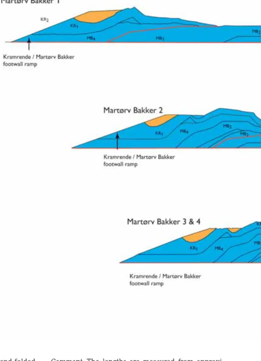
Martørv Bakker Section
The development in the Martørv Bakker Section was dominated by the translation of a thrust sheet that was more than 600 m long and only 20–30 m thick. During nearly 400 m of displacement towards the fore-land, a lower segment transformed into a duplex that ramped at a relatively late stage and created a
fault-Fig. 120. Dynamic model of progr essive deformation in the Martørv Bakker Section illustrated in thr ee sequential restoration cross-sections. The cross-sections demon-strate four stages in the development between the balanced cross-section and the structural cross-section (Plate 2). The red
lines indicate the active displacement
sur faces in each deformation stage. Note the significant depression for med in the hang-ing-wall block south of the Martørv Bakker normal fault. In this depression, diamictites interlayered with slump-slides wer e depo-sited.
bend-fold anticline and syncline pair. At the upper surface of the intervening limb between the fold pair, a foreland-dipping normal fault was for med, rather similar to the structural complex formed in the Br ede RendeSection. Simultaneously with the sedimentation of a diamictite, three slump-slides filled the piggyback basindeveloped in a syncline cr eated at the top of the hanging-wall block of the normal fault. The sequen-tial restoration stages ar e illustrated in three cross-sec-tions in Fig. 120.
Martørv Bakker stage 1. Thrusting in the Martørv Bakker Section started with foreland thrusting of MB02, and translation of the trailing-end duplex that
consti-tuted the KR01 thrust sheet emplaced piggyback on the MB04 thrust sheet, thrust up along the footwall ramp of MB03. The more than 600 m long MB02 thrust sheet was displaced c. 105 m over the footwall flat of MB01. The MB02 thrust fault included two ramps, an upper footwall ramp of MB01 and a lower ramp be-tween the 20 m flat level and the 30 m décollement level. The lower ramp was located below the central part of the MB02 thrust sheet, where it acted as the final step for the décollement level change to the 20 m footwall flat level. It is thought unlikely that signif-icant sedimentation occurred in the section during this stage.
Martørv Bakker stage 2. The MB01 thrust sheet was displaced about 100 m over the foreland of the Stens-næs Section along the leading-edge thrust. The MB01 thrust was rooted down to the 20 m flat level, and it canbetraced further on to the 30 m décollement level by passing the central lower footwall ramp of MB02. Minor adjustments along the hanging-wall flat result-ed in formation of small duplexes along the thrust fault. In the trailing end of the section, the MB03 thrust sheet was thrust up over the footwall ramp of MB02, whereby an antifor mal stack was for med due to the folding that also involved the MB04 and KR01 thrust sheets. At the base of the MB03 thrust sheet, the low-er segments for med an irregular duplex, which ac-centuated the antifor mal stack. The accumulated dis-placement ranged up to 290 m.
Martørv Bakker stage 3. The final thrusting of the Martørv Bakker Section was concluded by nearly 100 m displacement of the MB02 thrust sheet. The frontal hanging-wall ramp-and-flat was thrust over the piggy-back basin of the SN04 thrust sheet in the Stensnæs Section. During the thrusting, the lower segment MB02u was activated and formed a fault-bend-folded lower duplex. Above the hanging-wall ramp of the trailing-end segment (MB02u3), an anticline was for med at the surface of MB02 and a subsequent syn-cline above the hanging-wall/footwall flat became a piggyback basin.
Martørv Bakker stage 4. The foreland-dipping limb of thefold pair at the top of the MB02 thrust sheet devel-oped into a southerly dipping nor mal fault. The c. 10 m deep piggyback basin was filled with diamictitic deposits and slump-sheets that glided down from the top of the antifor mal stack. Deformation in the Mar-tørv Bakker Section concluded with the steepening up of the leading-edge thrust structur es due to ramp bending in the Stensnæs Section.
Martørv Bakker Section: s
umm
ary data
Balanced length (L0): 1065 m
Cross-section length (L1): 675 m Shortening (ΔL): 390 m
Compression: 36.6%
Comment. The lengths ar e measured from the tip of the leading-edge hanging-wall ramp to the upper bend of the footwall ramp of the MB04 thrust sheet.
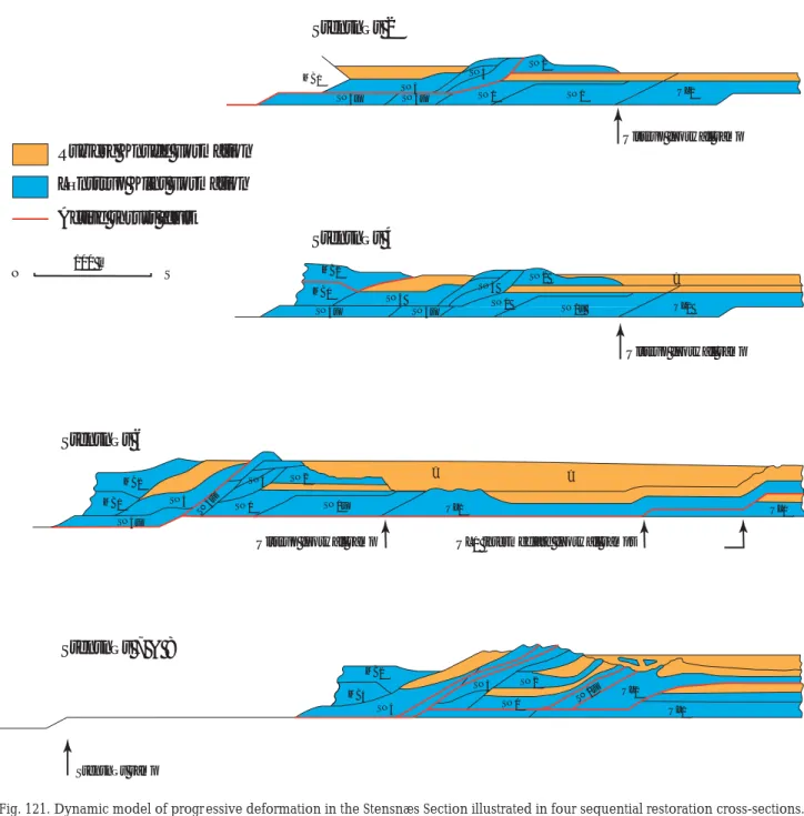
Stensnæs Section
In the Stensnæs Section, a number of conspicuous flexural slip folds occur which are interpreted to have resulted from the deformation that accompanied se-quential footwall ramp collapse and subsequent ramp displacement of minor duplexes. It is significant that they occur in relation to the final ramping from the lower 20 m flat level to the upper 10 m flat level. Eight stages have been differentiated in the development of the Stensnæs Section, of which stages 2, 4 and 6–8 are illustrated by the cross-sections in Fig. 121.
Stensnæs stage 1. In contrast to the Martørv Bakker Section, an initial sediment thickness of 5 m of the Rubjerg Knude Formation is thought to have covered the Stensnæs Section. It should be noted, however, that typical Lønstrup Formation facies grade upwards into typical Rubjerg Knude Formation facies in this distal part of the Rubjerg Knude Glaciotectonic Com-plex; the L/R-unconformity is not clearly developed, and location of the formation boundary can be diffi-cult. The affinities of the sediment packet referred to above are thus debatable.
Stensnæs stage 2. Thrusting in the Stensnæs Section was initiated with c. 100 m displacement of the SN02 thrust sheet over the upper flat. The thrust fault ramped down to the 10 m flat level, which separated the up-per and lower segments of the SN04 thrust sheet, si-multaneously with stacking the SN03 thrust sheet into a northerly dipping duplex complex along the foot-wall ramp of SN01.
Stensnæs stage 3. Accumulation of the Rubjerg Knude Formation incr eased to a sediment thickness of 10 m. Sedimentation was restricted to the piggyback basin of the SN04 thrust sheet, as well as on the foreland south of the frontal tip of the SN02 thrust sheet.
Stensnæs stage 4. The piggyback basin on the back of SN04 was sealed in by the overthrusting of the MB02 thrust sheet; this is equivalent to stage 3 in the Mar-tørv Bakker Section.
Stensnæs stage 5. As a trailing-end structural complex to the Ulstrup Section, the thrust sheets of the Stens-næs Section were translated together with the UL02 thrust sheet over the Ulstrup footwall ramp onto the hanging-wall flat of the foreland. During ramping, the SN01 and SN03 thrust sheets were separated into small duplex segments. Flexural-slip folding and polyphase
UL1 intermediate footwall ramps Ulstrup footwall ramp
Stensnæs 2
Ulstrup footwall ramp
MB1
SN4
SN4u SN4u SN1 SN1 UL2
SN3 SN2
Stensnæs 4
Ulstrup footwall ramp
MB2 MB1 SN4u SN4u SN4 SN3 SN2 SN1 SN1u UL2 ? Stensnæs 6 MB1 SN4u SN4 SN3 SN2
SN4u SN1 SN1u UL2 UL1
MB2 ? ? Stensnæs 7 & 8 Stensnæs ramp MB2 MB4 SN4 SN3 SN2 SN1 SN1u UL2 UL1
Lønstrup Klint Formation Active thrust fault
Rubjerg Knude Formation
100 m
N S
Fig. 121. Dynamic model of progr essive deformation in the Stensnæs Section illustrated in four sequential restoration cross-sections. The cross-sections demonstrate five of the eight stages in the development described in the text between the balanced cross-section and the structural cross-section (Plate 2). The red lines indicate the active displacement surfaces in each deformation stage.
hydrodynamic brecciation resulted from the ramping (Figs 53, 57, 58). The accumulated displacement ranged up to 35 m, whereas the length of the hanging-wall flat in the 10 m flat level amounted to 500 m. At the leading edge of thrusting, the UL02 thrust sheet initia-ted the thrusting up over a stepwise ramp.
Stensnæs stage 6. During this stage, about 10 m of the Rubjerg Knude Formation was deposited in the pig-gyback basin at the top of the SN02 thrust sheet. The
sedimentation level was probably up to 20 m above the L/R-unconfor mity, inferred from the elevated po-sition of the SN02 thrust sheet. However, this is un-certain and the sediments were either never deposit-ed or eroddeposit-ed away during later thrust elevation. In the norther n part of the section, the SN04 thrust sheet propagated up along the footwall ramp of the earlier created SN02–SN03 duplex. This r esulted in fault-bend folding of the SN04 thrust sheet and its piggyback basin as well as the overlying MB02 thrust sheet. This
stage correlates with stages 3–6 in the Martørv Bakker Section.
Stensnæs stage 7. The SN01 thrust sheet was displaced about50moveritslowersegment (SN01u), and together theywerethrust onto the footwall ramp-and-flatofthe UL02thrustsheet.During the thrust-fault propagation oftheUL02 thrust sheet over the footwall ramp of UL01, theSN01and SN02 thrust sheets, piggyback translated on UL02, wer e bent into c. 30° dipping position. Fi-nally, the SN04 thrust sheet was displaced up along the footwall ramp of SN03 during dif ferential duplex for mation along the SN04 hanging-wall ramp.
Stensnæs stage 8. The frontal parts of the SN01, SN02 and SN03 thrust sheets, as well as the anticlinal cr est
of the UL02 thrust sheet (formed above the upper hinge of footwall ramp of UL01), were significantly eroded, and a local piggyback basin was formed above the transition between the Stensnæs and Ulstrup Sections. To the north of this piggyback basin, the elevated and exposed tips of the SN02–SN04 thrust sheets grav-ity-slumped out into the basin, where they were de-posited as olistoliths, 1–5 m in size.
Stensnæs Section: s
umm
ary data
Balanced length (L0): 350 m Cross-section length (L1): 180 m Shortening (ΔL): 170 mUlstrup Section
Thin-skinned thrusting in the Ulstrup Section involved the remarkable translation of extensive, thin thrust sheets over the footwall flat of the foreland. Cohesion of the thrust sheet was probably increased by ground frost in the upper part of the thrust sheet, while the hanging-wallramp-and-flatslid on a thin zone of mo-bilised mud. During translation, piggyback sedimen-tation varied considerably. Six stages have been dif-ferentiated in the development of the Ulstrup Section; stages 1–3 and 5 are illustrated by the cross-sections in Fig. 122 (see also Fig. 121).
Ulstrup stage 1. Thrusting in the Ulstrup Section initia-ted with frontal ramping of the UL02 thrust sheet over a two-stepped footwall ramp of what was to become
theUL01thrustsheet. This ramping resulted in the for-mation of two, fault-propagating folded anticlines, which were separated by a shallow, broad syncline. The leading edge of the UL02 hanging-wall ramp was displacedabout 25 m over the c. 5–10 m thick Rubjerg Knude Formation deposited in the foreland (at the top of UL01). The UL02 hanging-wall flat extended along the upper 10 m flat level for about 400 m, ter mi-nating to the north at the foreland footwall ramp root-ing down to the 20 m décollement level. Thrust pro-pagation up over this ramp for med a hanging-wall anticline at the trailing end of the UL02 thrust sheet. Between the anticline at the trailing end and the anti-cline at the upper footwall ramp of UL01, a piggyback basin formed in which glaciolacustrine sediments wer e deposited to form the small, ephemeral Ulstrup lake.
Fig. 122. Dynamic model of progr essive deformation in the Ulstrup Section illustrated in four sequential restoration cr oss-sections. The cross-sections demonstrate four of the eight stages in the development described in the text between the balanced cross-section and the structural cross-section (Plate 2). The r ed lines indicate the active displacement surfaces in each deformation stage.
Ulstrupstage 2. Thrusting along the UL02 hanging-wall ramp-and-flatpr ogressedwith an accumulated displace-mentof230m.Theglaciolacustrinedepositsofthe ephe-meral Ulstrup lake participated in the ramp-propagat-ing-folding. During translation along the upper 10 m flatlevel,the trailingendoftheUL02thrustsheetwas pr obablycover edbysediments,whichsubsequently becameeroded.ThiseventintheRubjergKnudeFor -mationcorrespondedtostage6intheStensnæs Section.
Ulstrup stage 3. The long lateral thrusting of the UL02 thrust sheet along the upper flat resulted in 550 m of displacement, and at the lower trailing end, the hang-ing-wall ramp became detached to the upper footwall ramp of UL01. Above this ramp, conspicuous flexural-slip folds, similar to the folds developed in the Stens-næs Section, wer e formed in the UL02 thrust sheet.
Ulstrup stage 4. Glaciofluvial sands were deposited upon an erosional surface capping the Ulstrup lake sediments (all Rubjerg Knude For mation). Depositional base level was probably equivalent to that experienced in stage 8 in the adjacent Stensnæs Section (see above).
Ulstrup stage 5. The final foreland thrusting took place as the UL01 thrust sheet was thrust over the upper ramp of the foreland and propagated about 200 m to the south. When the anticline above the UL02 hang-ing-wall ramp approached the footwall ramp of the for eland, where a fault-bend formed continuously during the propagation of the UL01 thrust sheet, a narr ow channel was formed in which coarse-grained glaciofluvial gravel was deposited (Figs 27, 122). The gravel also included r edeposited frozen blocks of sand, testifying to the ground-frozen conditions of the en-vironment (Fig. 28).
Ulstrup stage 6. At the leading edge of the UL01 thrust fault, the defor mation concluded with 150 m of dis-placement over the upper footwall flat of the for e-land. During the translation of the UL01 thrust sheet over a minor depr ession in the foreland, a sandy mud volcano developed due to trapping of the high water pr essure close to the leading-edge thrust. The sedi-ment extrusion r esulted in chaotic disturbances in the central part of UL01.
Ulstrup stage 7. The last stage of development in the Ulstrup Section involved sedimentation of the upper -most post-tectonic deposits of the Rubjerg Knude For-mation. The conglomerate (of stage 5) was covered
by sand, and deposition in the foreland covered the leading-edge thrust at Tvonnet Rende (for location see Plate 1).
Ulstr
u
p Section: s
umm
ary data
Balanced length (L0): c. 1350 m Cross-section length (L1): c. 850 m Shortening (ΔL): c. 500 mCompression: c. 37%
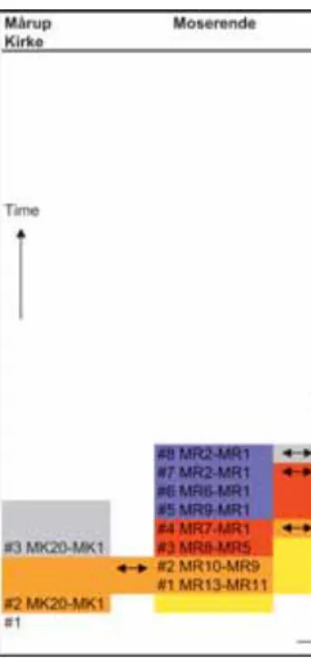
Summary of dynamic development
The dynamic development of the complex is summa-rised in Figs 123 and 124. From the scheme in Fig. 123, it is clear that the Rubjerg Knude Glaciotectonic Complex developed in sequential progressive stages during syntectonic sedimentation of the Rubjerg Knu-de Formation.
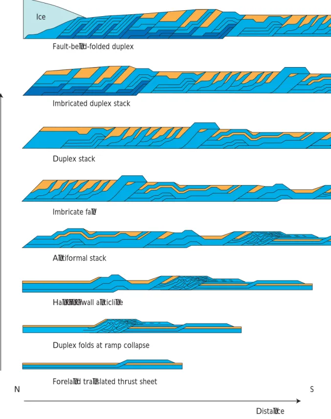
The thin-skinned thrust-fault complex developed mainly as piggyback thrusting with proximal thrust sheets being displaced contemporaneously with acti-vation of the distal thrust fault. During the advance of the thrust-fault complex, the position of the décolle-ment zone shifted progressively to deeper levels. The dynamic development can be summarised in eight steps that resulted in the formation of eight character-istic thrust-fault structure types (Fig. 124).
Fig. 123. Summary scheme of the syntectonic sedimentary development in the Rubjerg Knude Glaciotectonic Complex. The deformation stages for each section, as described in the text, are indicated here by the symbol #.
1. Long lateral translation of a thin thrust sheet took place over the foreland. The ramp was rooted in the uppermost shallow décollement level 1 at a depth of c. 10 m from the top surface.
2. Ramps became rooted in décollement level 2, and the increase in ramp height, amounting to about 20 m, is regarded to be the cause of the duplex folding at ramp collapse.
3. Thehanging-wall anticlines became dominant struc-tur es with hinterland-dipping piggyback thrust sheets on the back limb. As the ramps extended down into décollement level 3, the height of the ramps increased and consequently the hanging-wall anticlines increased in size.
4. The antifor mal stack developed, which included long-distance translated piggyback thrust sheets that were folded in a hanging-wall anticline. In relation to the antiformal stack, for eland-dipping thrust faults occur that were accompanied by nor-mal faults.
5. The prominent imbricate fan formed above décol-lement level 2. The initially gently to moderately dipping imbricated thrust sheets wer e re-orientat-ed into steeply dipping positions due to lateral translation of the imbricate fan along décollement level 3.
6. This step involved the subsequent deformation of the lower duplex segment not incorporated in the imbricate fan. This lower duplex segment was im-bricated and the sub-segments were displaced in-to a duplex stack during push from behind by a
pr ogressing hanging-wall ramp, rooting in décol-lement level 3.
7. This step involved differential duplex stacking and imbrication of thrust-fault sheets. The piggyback basins vary in elevation due to differences in du-plex stacking. Further more, the variation in dudu-plex stacking reflects the shift from décollement level 3 to 4 (corr esponding to a shift in the décollement sur face from 30 to 40 m).
8. The fault-bend-folded duplex units were formed. The formation of these duplex units was only pos-sible because the four thrust-fault flat levels had developed, and thus the duplexes could be stacked and subsequently fault-bend-folded during maxi-mum compr ession and translation along décolle-ment level 4 (Fig. 124).
The thickness of sediments that accumulated contem-poraneously in tectonically correlated piggyback ba-sins decreases from north to south. Thus the depo-centre was situated in front of the last activated thrust section, and the depocentr e gradually shifted to a more and more distal position. Corr elation of the syntec-tonic progressive development of the complex shows that sedimentation was contemporaneous with thrust-ing rather than there bethrust-ing an alternation between periods of active thrust faulting and periods of depo-sition. Further more, it indicates that the ice margin was not melting back during the formation of the com-plex but advanced in a continuous pr ogressive gravi-ty-spr eading process.
Ice
Fault-bend-folded duplex
Imbricated duplex stack
Duplex stack
Imbricate fan
Antiformal stack
Hanging-wall anticline
Duplex folds at ramp collapse
Foreland translated thrust sheet
Distance
Time
S N
Fig. 124. Model of thrust-fault structure types formed during the progressive defor mation of the thin-skinned glacio-tectonic thrust-fault complex. The model outlines a progressive development in eight steps resulting in the for mation of eight characteristic thrust-fault structure types, the first to develop earliest and continuously in the distal part of the complex, and the last to be formed in the most proximal part of the complex (see text for details).
Lønstrup Klint Formation
Rubjerg Knude Formation
Discussion
The observations that form the basis for the descrip-tion of the structural geology, mechanical behaviour and dynamic development of the Rubjerg Knude Gla-ciotectonic Complex, raise important questions with respect to understanding the framework and nature of thin-skinned thrusting related to glacial defor ma-tion;seventopicshavebeenselectedforfurther discus-sion below. The basis for understanding a structural complex is to describe the tectonic architectur e and the range of structur es it contains from microscopic to macroscopicscale.The discussionofthrust-fault archi-tecture leads to evaluation of the reliability of the balan-ced cross-section. Consideration of thrust brecciation and diapirism leads naturally to a focus on the thrustfault dynamics, and the significance of the rate of defor -mation. The dynamics associated with the syntecton-ic deposits and the formation of piggyback basins merit discussion, as does the interpretation of a pr oglacial
contra subglacial deformational setting. The final topic dealswiththegeologicalsettingofthecomplex, inclu-ding the timing of the event that created it.
Thrust-fault architecture
A pr erequisite for understanding the thrustfault ar -chitectur e is a familiarity with the terminology (see Appendix 2). The macroscopic structures encountered inthin-skinnedorogenicbeltsar eallrecognisablein the glaciotectonic complex. Mesoscopic structur es such asfoldsandfaultsaresimilarlyrecognisable.However, small-scale structures such as joints, cleavage and fabric ar e more difficult to recognise (except for hydrody-namic br ecciation), and this may be one of the major dif ferences between soft sedimentary defor mation and hard-r ock deformation.
It seems likely that joints and fractures in soft sedi-mentswould be able to re-heal after deformation. Thus, a large number of minor reverse faults must have for med in thrust sheets during ramp propagation (Fig. 67), but appear to have disappeared again after sub-sequent thrust sheet propagation along the flat, as theyhavenotbeenobserved with the exception of the
in situ positions related to ramp bend (Fig. 85). There is an approximation to a right-angle r elationship be-tween the footwall ramp and the back-thrust faults,
which indicates that an increase in the dip of the foot-wall ramp results in a decrease in the dip, in the op-posite direction, of the back thrust. Mor eover, a steeper and higher footwall ramp also corresponds to an in-crease in displacement along the back-thrust fault. Thus onecan regard the KR01 (Kramrende) back-thrust faults as structures related to initial faulting in the progr es-sive deformation (Fig. 67), and the KR04 back-thrust splay faults as a structural element related to a devel-oped phase of progressive thrust-fault deformation (Fig. 72). Major back thrusting at the back of SR02 (Fig. 84) represents a matur e phase in the progressive thrust faulting. The apparent lack of joints and frac-tures reflecting ramp propagation could probably be explained as having been absorbed in the hydrody-namic brecciation process.
Among the structural elements analysed during the interpretation of the balanced cross-section, the du-plex structures create the most inter esting problems. Firstly, the interpretation of the duplex imbricates in the Stensnæs Section provides an explanation for the complicated fold framework. Secondly, the interpre-tation of the duplex below the frontal part of the Stor-torn Section links the hidden duplex segments at the base of the Grønne Rende Section with the duplex stacking below ST01–ST03. Thirdly, the normal faults can be interpreted to have been r elated to the ramp-ing of lower duplex segments. If the normal faults are regarded as foreland-dipping faults or part of a for e-land-dipping duplex, the model for duplex formation suggested by Contreras & Sutter (1997) may be rele-vant for the understanding of the foreland-dipping faults. In their model for formation of foreland- or hinterland-dipping duplexes, they considered two fac-tors: u = distance of displacement along the upper flat, and s = length of duplex segment. In a regime where the ratio u/s is greater than one (u/s > 1), for e-land-dipping duplexes are formed; in a regime where u/s < ½, hinterland-dipping duplexes are formed. In regimes where ½ < u/s < 1 or u/s = 1, antiformal stacks or angular antiformal stacks, respectively, are formed. This corresponds well to the interpr etation presented here of the Rubjer g Knude cross-section, where most thrust sheets are displaced by less than their length, and consequently the main orientation of thrust sheets is hinterland dipping. According to the model of Contreras & Sutter (1997),
foreland-dip-ping duplexes are formed when a duplex segment is displaced along an intermediate or upper flat for a distance equal to, or more than, its length. A conse-quence of this is that a roofing thrust sheet will be displaced in front of