Generating Interaction Test Cases for Mobile Phone
Systems from Use Case Specifications
André L. L. de Figueiredo
GMF/DSC – Universidade Federal de
Campina Grande (UFCG) Caixa
Postal 10.106 – 58109-970 – Campina
Grande – PB – Brasil
[email protected]
Wilkerson L. Andrade
COPIN/DSC – Universidade Federal
de Campina Grande (UFCG) Caixa
Postal 10.106 – 58109-970 – Campina
Grande – PB – Brasil
[email protected]
Patrícia D. L. Machado
COPIN/DSC – Universidade Federal
de Campina Grande (UFCG) Caixa
Postal 10.106 – 58109-970 – Campina
Grande – PB – Brasil
[email protected]
ABSTRACT
The mobile phone market has become even more competitive, demanding high quality standards. In this context, applications are built as sets of functionalities, called features. Such features are combined in use scenarios of the application. Due to the fact that the features are usually developed in isolation, the tests of their interactions in such scenarios are compromised. In this paper, we present a proposal of specifying feature interaction requirements with use cases; generating a behavioral model from such specification; and a strategy for generating test cases from the behavioral model that aims to extract feature interaction scenarios in such a way that interactions can be tested.
Categories and Subject Descriptors
D.2.1 [Software Engineering]: Requirements/Specifications –
methodologies, tools. D.2.4 [Software Engineering]:
Software/Program Verification – validation. D.2.5 [Software Engineering]: Testing and Debugging – testing tools.
General Terms
Algorithms, Verification.
Keywords
Feature interaction, software testing, use case.
1.
INTRODUCTION
The mobile phone market has grown even more in the lasts years, with this type of mobile communication device becoming sufficiently popular. It is happening in a way that the system responsible for controlling these devices has become highly complex, due to both the need of evolving due to the market dispute and the need of coming along with the hardware and network infrastructure evolution. On one hand, the need of quality products is eminent in front of this competitive market. On the other hand, the systems complexity lead us to a context where
reaching such quality levels demands effective tools and techniques.
An important characteristic of this type of system is that its development happens in an evolutionary manner, where new functionality sets (called features, e.g., send and receive text messages) are inserted into the previously developed versions. In general, the new features are developed and tested in isolation, or at least with the features that they depend on [4].
However, handling the features in isolation can cause some problems, as that caused by the feature interactions. The term interaction between features has been used by the community to express the problems caused by functionality added to the systems that generate conflicts with features already added [2, 4, 6, 10]. For instance, a feature that redirect a call from B to C when the mobile phone A is busy, can conflict with other feature that show the B mobile phone number to the user of A when A is busy. We can say, in this case, that feature interaction occurs if the features work in isolation, but the same system will not be able to implement both features.
In our context, we call feature interactions the flows where a feature functionality interact in some way with a functionality of the other feature. For instance, when a user is composing a text message, an incoming call can arrive, causing an interaction between the features of send message and incoming call. In these cases, we identify the flow that is executing (called the main flow) and another caused by an interruption. In the example, the composing message is the main flow and the interruption is that caused by the incoming call flow. This example do not show the conflict between requirements, as we previously mentioned for the features interaction term, however this is a flow that is not usually specified, due to fact that the features are developed and tested in isolation.
Software testing has being used in mobile phone applications as an important tool for evaluating system quality. However, besides the known difficulties of testing distributed [5, 9] and mobile systems, the test of this king of system present other difficulties, such as feature interactions. Since the features are developed and tested in isolation, feature interaction testing can be neglected. This work is part of a research project from a cooperation between Motorola and CIn-UFPE/Brazil. The main goal of the project is defining an integrated process for generating, selecting and evaluating mobile phone applications test cases. While other works in this project deal with features in isolation, as we
Permission to make digital or hard copies of all or part of this work for personal or classroom use is granted without fee provided that copies are not made or distributed for profit or commercial advantage and that copies bear this notice and the full citation on the first page. To copy otherwise, or republish, to post on servers or to redistribute to lists, requires prior specific permission and/or a fee.
previously said, in this paper, we present a proposal in which features interactions information are added to the features development process, making test case generation for testing such interactions possible. The proposal consists of:
• A way of specifying interactions in use cases;
• A behavioral model architecture, based on the CSP notation, in which feature interactions can be presented; • A strategy for feature interaction test case generation. This paper is structured as follows. In Section 2, an overview of CSP [8] is presented. In Section 3, the context where our proposal is inserted into is presented. In the Sections 4, 5, and 6 we present our proposal showing, respectively, how to specify feature interactions in use cases, the behavioral model generated from those use cases, and a strategy for test cases generation. In Section 7, we discuss the related works. Finally, the conclusions are showed in Section 8.
2.
CSP OVERVIEW
The process algebra CSP is a formal specification language primarily designed to describe the behavior of concurrent and distributed systems [14]. The fundamental idea of CSP is a communication based on events; events are abstractions of real world actions. Events are assumed to be drawn from a set ∑, the alphabet of a specification. Thus, the set ∑ contains all possible communications that a CSP specification can perform.
In a specification, events are introduced by channel declarations; channels can be typed or untyped. Untyped channels (turnOn)
are indeed events (or simply synchronization points) whereas typed channels (send) are collection of events (also seen as
vehicles to communicate data of the respective type). Types are built-in (Int for integers) or user-defined (datatype denotes
enumerations and nametype abbreviations). The following
fragment of a CSP specification illustrates these elements:
datatype MESSAGES = SMS | MMS | EMS nametype PHONE = Int
channel turnOn
channel send, receive: MESSAGES.PHONE
The typed channel send can communicate any data from the
composed type MESSAGES.PHONE. Thus, an event from this
collection is an element whose name is send, followed by (.) a
value formed from the enumerated type MESSAGES (or an SMS, MMS or EMS message), followed by (.) a phone, specified by the
type PHONE (the integers set). For instance, one such an element
is send.SMS.1.
Typed events can be used to input or output data. Thus, to describe an input using the channel receive, we write receive?msg?phone. This pattern introduces two variables: msg and phone. Their values are only determined after a
communication has occurred successfully.
CSP uses the concept of process to input or output data, synchronize communications, and describe behaviors. A process is a behavioral unit. Here, we consider the following simplified CSP process grammar: P ::= STOP | SKIP | a -> P | P |˜| P | P [] P | P [|X|]P | Q
The communication between two processes can only occur through synchronization, i.e., the same event occur in two processes at the same time.
In CSP, two basic processes deserve special attention: the first is the process STOP, which represents a broken machine (that is, a
machine that is unable to communicate anything), and the second is the process SKIP used to denote a successfully terminated
process.
The simplest behavior, with the exception of STOP and SKIP, is
given by the prefix (->) operator. The process e -> P offers the
event e to its environment and waits indefinitely for its
occurrence. Once the event e occurs, the process e -> P
behaves like P. A CSP environment is anything which can
interact with a process.
Alternative behavior is characterized by two kinds of choice operators: The internal or non-deterministic choice (|˜|) and the
external or deterministic choice ([]). The process P |˜| Q
behaves like P or Q independent of the environment. That is, the
process P |˜| Q passes to behave like P or Q and only after that
the environment can interact with it. On the other hand, the process P [] Q can behave like P or Q but the choice is decided
by the environment. That is, if the environment is only able to interact with P, then P is chosen, otherwise Q is chosen.
Processes can be combined to describe the architecture of systems through parallel composition. The parallel composition, denoted by [|X|], is used to put two processes in parallel, in which case
they should synchronize in all communication events in the set X.
For instance, the process P [|ch|] Q describes the parallel
composition of processes P and Q, where they should execute all
events from channel ch simultaneously. Events outside X should
be executed independently on each process.
A CSP process is defined by an equation, where the left-hand side has the name of the process with eventual parameters, and the right-hand side has a process body given by a composition of the previous operators. The following equation defines the process
TEST_CASE_1 as a series of prefixes terminating successfully. TEST_CASE_1 =
setup -> goTo.MESSAGE_EDITOR.1 -> create.SMS.1 -> test -> send.SMS.1 -> receive?mesg.1 > open.mesg > cleanup -> delete.mesg --> goTo.IDLE --> SKIP
To capture non-terminating behavior, we simply use recursive processes. The last element of the simplified CSP process grammar refers to a recursive process call (Q). This occurs when
in the right-hand side of an equation, P = ... Q, the name of a
process corresponds to the left-hand side of some (other or the same) equation (Q = ...).
In this case, the behavior is simply transferred to the right-hand side of the called process. Therefore, recursive behavior allows infinite system modeling.
3.
BACKGROUND
In this section, we present the context where our solution is inserted. Such context is related to the other works of our project that are straightly connected to our proposal. Thus, as mentioned in Section 1, the features are implemented and tested in isolation. As we are interested about test, we present the process from a tester’s point of view, from the requirements specification to test case generation. We do not present details of test case execution because it is not in the context of our work, which is limited to identifying the test cases.
In general, the process is as follows: first, the feature requirements are specified in use cases using a controlled natural language; second, the behavioral model is generated in CSP from use cases; and finally, the test cases are extracted from this behavioral model, as is shown in Figure 1.
Figure 1. General view of feature test process
In the next subsections, we show, through an example, how each step of the process is contemplated in other to illustrate the context where our proposal is inserted into. Our use case example is called “Moving a Message from inbox to the Hot Message folder”, which means that a new folder used for store the user’s favorite messages is added to the mobile phone. The user can move messages to this new folder through shortcuts as well as perform other operations relating to the new folder.
3.1
Feature Requirements Specification in the
Use Cases Notation
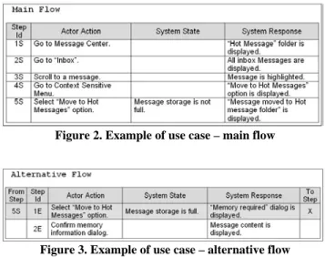
The features are specified as use cases using a controlled natural language as the example shows in Figure 2 [3]. The controlled natural language is a subset of natural language (English) with a fixed grammar, in order to allow an automatic processing. Figure 2 presents the main flow of the use case, whereas Figure 3 presents an alternate flow. The flows are described through steps that include a user action and the respective system response. For instance, the step “5S” has the selection of the option “Move to Hot Message”, and the respective system response is to show an alert saying that the message was moved.
Besides the actor action and the system response, each step has a condition (System State) that determines if the system response will happen or not. If the condition is not satisfied, an alternative flow must be specified, we have as an example the step “5S” of the main flow that has one alternative flow (steps “1E” and “2E” in Figure 3).
Figure 2. Example of use case – main flow
Figure 3. Example of use case – alternative flow
3.2
Generating the Behavioral Model in CSP
The general strategy for test cases generation consists of obtaining a formal behavioral model in CSP (automatic generation [3]) from the feature use cases. Then, using a test case extraction tool [13], the test cases can be obtained. In this section, we present the CSP model structure generated from use cases, however the algorithm for such generation will be not presented in details.
In this CSP model, each use case will be modeled by a process. The system process (System), as a whole, will consist of a
random choice between the use cases processes, as the Figure 4 shows.
Figure 4. CSP behavioral model – System process
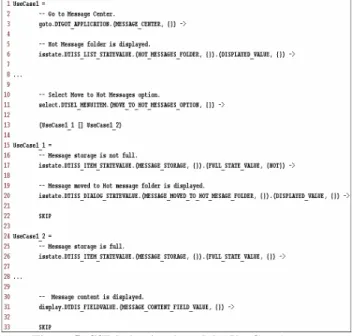
For instance, the UseCase1 process can model the use case
presented in Figures 2 and 3.
In the CSP Model, each use case step, both user action and system response, will be modeled as an event of the respective process. In our context, the events are automatically generated from the use case phrase, using a tool [11]. The tool [11] generates CSP events from the controlled natural language (English phrases). For instance, such tool receives as input the phrase “Go to Message Center” and returns the respective CSP event
“goto.DTGOT_APPLICATION. (MESSAGE_CENTER,
{})”. The CSP behavioral model is automatically generated
using another tool [3] that is responsible for generating formal specifications from requirement documents. With the first tool that generates CSP events from phrases, and the second tool that, given a use case set, it generates a CSP behavioral model, we obtain the model presented in Figure 5.
Note that the main flow is modeled in the UseCase1 and UseCase1_1 processes and the alternative flow is in UseCase1_2. Thus, the choice shown in line 13 represents the
condition contained in the use case related to the step “5S”. Feature Specification as Use Cases Behavioral Model in CSP Test Cases
Figure 5. CSP behavioral model – UseCase1 process
3.3
Test Case Generation
From the generated behavioral model presented in the previous subsection, a test case generation tool [13] based on test purposes [16] can be run to generate test cases. Test purposes are system properties which the test cases must satisfy. Following the example shown in the previous subsections, a possible test purpose could be:
UNTIL “Message moved to Hot Message Folder” is displayed. This test purpose, using the UNTIL notation, represents all system executions that make the system display the message “Message moved to Hot Message Folder”. As an example of a test case generated from the UseCase1 process (see Figure 5), we have
that shown in Figure 6. Note that the test case expression takes the system to the response “Message moved to Hot Message Folder”.
Figure 6. Test case
4.
INTERRUPTION SPECIFICATION IN
USE CASES
As shown in the previous section, each feature is specified and tested in isolation. As the use cases, and consequently the generated behavioral model, do not have any information about features interactions, test cases for such cannot be generated. In this section, we will present an approach for specifying flows that cause feature interactions, called interruptions, as well as flows that do not permit or redefine interruptions behaviors.
The features interactions occur when a feature is executing a flow and other flow from another feature interrupt the first flow and then, begin its execution. For instance, given that a compose text message flow, of a send messages feature, is executing, i.e., the user is composing a text message. Then, an incoming call can arrive characterizing the interaction between send message and incoming call features.
For this flow to be present in the behavioral model and, consequently, test cases that exercise it can be identified, we need to: (1) specify the interrupt flow in use cases and (2) the main flow need to allow such interruption to occur. In Figure 7, we have an example of incoming message interruption use case.
Figure 7. Incoming message interruption use case
The interruption use cases are specified when the feature related to that interruption is developed, and will be useful as default behavior for all other features that can interact with this interruption. The first step of the use case main flow contains condition information (System State) whose value is the interruption name, and the system response to when this interruption occur, that is, in this case it is shows an incoming message alert. The remaining parts of the flow are like a normal use case, including the alternate flows.
Once this interruption flow is specified, we assume that it can be executed at any time that another use case is executing. However, some flows can forbid any interruption or redefine its behavior. Using the use case presented in Section 3, we specify some interruption flows, as shown in Figure 8.
Figure 8. Interruptions behavior specification
A new table called Interruptions is added to the use case. In this table, we can specify interruptions that are not permitted, specifically one or all, as in the step “2I” (Figure 8). Moreover, the interruption behavior can be redefined, as occur in the step “1I” (Figure 8), where, with incoming message interruption, the system behavior will be only to show an alert informing that a new message has arrived. This behavior is different from the default, where the read message option is shown too. Each interruption table entry set refers to a main or alternative flow step, as the column “From Step” specifies. The acronyms AA and SR inform if the specification refers, respectively, to occurred interruption before the actor action or the system response. In practice, with the specification presented in Figure 8, whenever a new message arrives when the user selects the move message to Hot Messages folder, only an alert will appear (step “1I” of Figure 8). Moreover, when a memory insufficient dialog box appears to the user, no interruptions can occur before the user confirms the message (step “2I” of Figure 8).
In summary, our strategy for interruptions specification in use cases consists of:
• Specify the default flows for interruptions as a use case when a feature inserts a new interruption on the system (see Figure 7);
• For each use case step, specify in the Interruption table (see Figure 8) if the interruptions are permitted or not, and the redefined behavior for each specific step. By default, the interruptions are permitted.
With this strategy of interruptions specification, interruptions behavior are defined during features development, without changing the typical development of features in isolation. Moreover, each specific feature can redefine the behavior of each interruption in each use case step, including, not permitting their execution. Thus as shown in the next sections, these information are used to build a behavioral model in CSP from where the test cases are extracted.
5.
BEHAVIORAL MODEL GENERATION
FROM USE CASE
With the feature use cases, a CSP behavioral model is generated, as shown in Section 3. However, as well as the use cases presented, the behavioral model do not have interruption information and then, flows with features interactions are not generated. In this section, we present the CSP behavioral model architecture that can generate flows with interruptions. Then, we show how the use cases presented in Section 4 are used to get the behavioral model.
For the sake of simplicity, Figure 9 shows a general view of the proposed solution to the CSP behavioral model. In that model, we
can see the behavioral model processes. Besides the process that execute a feature general use cases (Feature X) and a process that represents the feature interruption use cases (Feature Y), the model presents two other processes responsible for launch and manage the interruptions. It is important to note that this is a behavioral model, and that such processes do not have any relation to the possible software components.
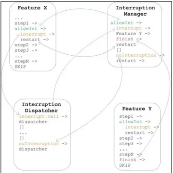
Figure 9. General view of the behavioral model
Figure 9 presents an example of a model where we have “Feature X” as a main feature (that is executing), “Interruption Dispatcher” as a process responsible for generating interruptions, “Interruption Manager” as a process responsible for delegating the interruption handling to the responsible features, and “Feature Y” as a feature responsible for handling a specific interruption. The “Interruption Dispatcher” communicates with the “Interruption Manager” through two signals: interrupt and noInterruption. With the interrupt signal we have that an interruption has occurred in the system, for instance, an incoming message. And with the noInterruption signal follows the information that no interruption has occurred. The features communicate with the “Interruption Manager” through four signals: allowInterruption, interrupt, restart, and finish. allowInterruption is used by the features to inform the “Interruption Manager” that in that executing point interruptions are allowed. interrupt is used by “Interruption Manager” to inform the features that an interruption has occurred. restart is used by “Interruption Manager” to inform the feature that it can continue its execution. And finish signal is used by the features that handle interruptions to inform the “Interruption Manager” that such handling has finished.
As we can see in Figure 9, an example of this model flow would be as follows. After the Feature X executes a specific step (step1), it sends an allowInterruption signal to “Interruption Manager”
informing that in that point interruptions are allowed. At this moment, the “Interruption Dispatcher” can send a noInterruption signal informing that no interruption has occurred, or interrupt, making the “Interruption Manager” transfer the execution to the Feature Y, that is responsible for the interruption handling. When this feature finishes the handling, a finish signal is sent to “Interruption Manager” that send a restart signal to the main feature (Feature X), so that it continues its execution.
Notice that the “Interruption Manager” process has a feature scheduling as its main functionality, defining which feature should be executing at a time. In our behavioral model, the interruptions event is a random event generated by the “Interruption Dispatcher”. It is important to remark that the presented model captures the parallelism that there is between the features execution and the model is very scaleable in a way that we can model even nested interruptions.
5.1
CSP Behavioral Model
The behavioural model is specified in CSP, where each component is modeled as a CSP process, as we showed in Section 3. Due to space restrictions, we present only fragments of the extended CSP model.
Figure 10 presents the process that models the system without interruptions (System), as we showed in Section 3, and the process that represents the system with interruptions behaviors (System_INT). This system consists of the parallel execution of the feature (use cases set), the process relating to the “Interruption Manager”, and the process relating to the “Interruption Dispatcher”.
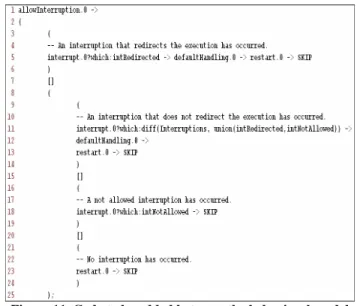
Figure 5 presents a portion of the CSP model relating to the respective feature. For this CSP model be able to interact with the “Interruption Manager”, we need to add events to the model. Thus, we have to add the fragment code shown in Figure 11 between two events that allow interruptions. Note that the open parenthesis symbol in Line 2 (Figure 11) does not have the respective close parenthesis symbol, and therefore, we need to add a close parenthesis symbol at the final of each process for each fragment added. In the fragment (Figure 11), intRedirect is the interruption set that closes the use case flow. For instance, an interruption caused by low battery in the mobile phone turns off the device. The intNotAllowed set contains the not allowed interruptions.
Figure 10. CSP model with interruptions – System_INT process
Figure 11. Code to be added between the behavioral model events
The allowInterruption event in Line 1 (Figure 11) informs to the “Interruption Manager” that interruptions are allowed. In Line 5 (Figure 11), there will be synchronization if an interruption of the intRedirect set occurs, i.e., if an interruption that closes the use case flow occurs. In Line 11 (Figure 11), there will be synchronization if an interruption not belonging to the intRedirect set occurs, i.e., if an interruption that does not close the use case flow occurs. After synchronizing, the event defaultHandling informs to the “Interruption Manager” that the interruption behavior handling is default, i.e., there is not behavior redefinition to this step. The Line 18 (Figure 11) contains the handling for when a not allowed interruption occurs, and the Line 23 (Figure 11) contains the handling for when no interruption occurs. As we can see in Figure 11, the synchronization channels are indexed (in the figure, with value 0). This is due to the fact that the “Interruption Manager” can handle many features, as occur when interruptions interrupt the others interruptions behavior, and so on. In this way, we are using indexes to identify which feature is been handling, and as it is the main feature, i.e., the first that can be interrupted, its index is 0.
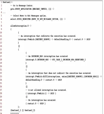
Thus, with the Figure 11 code fragment added, part of the model presented previously in Figure 5 can be seen in Figure 12, where such code fragment was added between the steps of Lines 3 and 31.
Figure 12. CSP model with interruption – UseCase1 process
The process that models the Interruption Dispatcher is presented in Figure 13. This process behaves as an interruption selector, that is, it can dispatch an interruption (intEvent.INCOMING_CALL or
intEvent.INCOMING_MSG) or not (noInterruption).
Figure 13. CSP model with interruption – INTERRUPTION_DISPATCHER process
A process fragment that models the Interruption Manager can be seen in Figure 14. When the feature synchronizes the allowInterruption event, the Interruption Dispatcher will dispatch an interruption or the event noInterruption (see Figure 13). If no interruption is dispatched (Line 17 in Figure 14), the Interruption Manager will only restart the feature execution (restart signal).
Figure 14. CSP model with interruption – INTERRUPTION_MANAGER process
If an interruption occurs, there are two possible behaviors:
• Default Behavior. When synchronizing the
defaultHandling event (Line 7 in Figure 14), the INTERRUPTION_PROCESS process begins to behave as a parallel process between the process responsible for the interruption behavior and itself, with the increased indexes (Line 9 in Figure 14).
• New Behavior. The feature itself defines the behavior,
and therefore the Interruption Manager does not need to do anything.
When a feature that is handling an interruption finishes its execution, it sends a finish signal (Line 30 in Figure 14) to the Interruption Manager that restart the last interrupted feature (restart.(index - 1)).
As we showed in the Section 3, a use case can contain a new behavior specification to a given interruption. In our example, such specification is present in the code fragment of the Figure 15. Note that the fragment between the Lines 16 and 19 (Figure 15) was added in order to redefine the behavior of the incoming message feature. If this interruption occurs, the behavior defined in the USE_CASE_1_INCOMING_MSG_REDEFINED_1 process will be executed instead of the default behavior, as we had specified in the Figure 8.
Figure 15. CSP model with interruption – UseCase1 process with redefined behavior
5.2
Behavioral Model Generation
Thus, as mentioned in Section 3, from the use cases specifications of features, a CSP behavioral model is generated. In this sense, using the use cases with interruptions information (presented in Section 4), and with the CSP behavioral model generated for features, we will present a strategy for the automatically generation of the extended behavioral model presented in this section.
As shown in Figure 10, the process relating to the system as a whole is placed in parallel with the Interruption Manager and the Interruption Dispatcher. The next step of the strategy is to insert the synchronization events with the Interruption Manager into the process relating to the use cases (e.g. UseCase1), according to the interruptions specifications. This step is composed, basically, of three rules:
Rule 1. The code present in Figure 11 must be added between
events where the interruptions are allowed.
Rule 2. No code needs to be added if no interruptions are
allowed, but if only an interruption set is not allowed , the code present in Figure 11 must be added, where the intNotAllowed set is a set containing such interruptions not allowed.
Rule 3. If an interruption is redefined, as we can see in Figure 8
for an incoming message interruption, its behavior must be specified in a new process (e.g. USE_CASE_1_INCOMING_MSG_REDEFINED_1) and a code, such as the one presented in Lines 16 to 19 (Figure 15), must be added.
6.
AUTOMATIC GENERATION OF TEST
CASES
We have shown in Section 3 that, from the CSP behavioral model, a test case generation tool, that does such generation based on test purpose, is used for obtaining test cases. Thus, we will show how to build test purposes in a way of generating test cases to the feature interaction test, i.e., test cases with interruptions flows (not possible before).
Test purpose is a system property specification that allows the test case generation to focus on the test of such property in the implementation. For this, we need to define some properties for interaction test. We divide the properties into two groups: specific properties for interruptions and properties extracted from requirements.
To generate specific test cases (e.g. INCOMING_MSG) for a given interruption, we have the test purpose of the Figure 16. This test purpose specifies flows where, before moving a message to the hot messages folder, an incoming call is received by the user.
Figure 16. Test purpose for INCOMING_MSG interruption
When we give this test purpose (Figure 16) together with the model presented in Section 5 as input to the test case generation tool, we will obtain the test cases set presented in Figure 17. The events between the Lines 5 and 12 (see Figure 17) represent the occurrence of the incoming message interruption. The other test cases generated will differ from this, for example, by the moment where the interruption will occur.
Figure 17. Test case for the Figure 6 test purpose
A test purpose can be specified for testing a requirement that is not present in the use case. For instance, we have the requirement
UNTIL “Incoming Message” alert is displayed
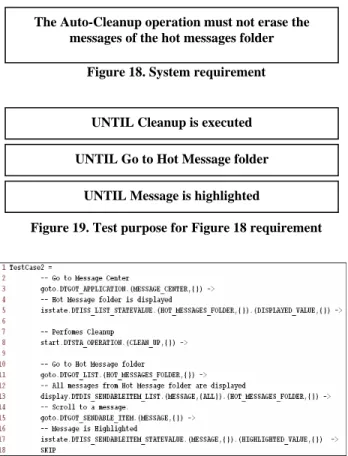
shown in Figure 18, which cannot be specified in use cases. However, we can test it using test purposes, as the test purpose presented in Figure 19. This test purpose will generate test cases where the Auto-Cleanup operation occurs, but soon later, at least one message can be founded in the hot messages folder, meaning that such operation did not change anything in the folder, as specifies the requirement of the Figure 18. Amongst such test cases, we have the test cases of the Figure 20.
Figure 18. System requirement
Figure 19. Test purpose for Figure 18 requirement
Figure 20. Test cases for Figure 16 test purpose
7.
RELATED WORKS
This section presents some works related to our proposal. Ryser and Glinz [15] show a practical approach to test systems using scenarios (use cases). They proposed a procedure to use scenarios in a defined way to systematically derive test cases for system test. This is done by formalization of natural language scenarios into state charts, annotation of state charts with helpful information for test case creation/generation and by the path traversal in the state charts to determine concrete test cases. As a drawback, we can mention the use of natural language, since a scenario transformed into a state chart by one developer may differ significantly from a state chart developed from the same scenario by another developer and it is very difficult to automate the process. Our proposal uses a template that is filled out with a controlled natural language, and then we obtain the behavioral model automatically.
Hartmann et al [7] present a way of generating integration test cases from UML State charts. Developers first define the dynamic
behavior of their components via UML State charts, specify the interactions amongst them (using CSP annotated in the diagrams) and finally annotate them with test requirements. Test cases are then derived from these annotated State charts using a tool developed by the authors. Besides the use of commercial UML modeling tools such as Rational Rose, the developers need to build state chart diagrams that are not very popular and know the process algebra CSP. In our proposal, the user only needs to fill out the templates and define the test purposes.
Bertolino and Gnesi [1] propose a methodology to manage the testing process of product lines, based on the requirements expressed in the use cases. The use cases are described through structured natural language in a proposed template, but the template does not allow specifying interactions between use cases.
Finally, Lorentsen et al [12] propose a way of identifying categories of interactions and create behavioral models that capture those interactions. They have been used Colored Petri Nets to manually model the interactions. The disadvantage of this proposal is because the developers need to know Petri Nets and the process is not automatic.
8.
CONCLUDING REMARKS
This paper presents a strategy for test case generation aiming to test feature interactions in a context where features are developed in isolation. Also, a way of specifying interaction requirements in use cases is presented. In this strategy, the engineer specifies the possible interruptions that can or cannot occur for a given use case step, besides the interruptions behavior. A CSP behavioral model architecture is presented, besides a strategy of generating such behavioral model from interruption specifications contained in the use cases. Finally, a strategy for generating test cases using a test purpose-based tool is presented, including possible ways of specifying the test purposes and how to build them.
Since the interruptions specification uses an existing template, our proposal of specifying interruptions will not have problems relating to the engineers acceptance that are responsible for writing requirements. They will continue writing the features requirements in isolation [3]. The example showed in this paper was used as case study in order to compare the current process used in Motorola with our proposal. We verified that in the current test case set there were tests only for the auto cleanup interruption. Our proposal added some kind of interruptions as incoming call, incoming message, and remove battery. As a result, we have seen that our proposal generated more test cases than the current process and our proposal identified new interactions scenarios that were not being exercised.
Relating to the process automation, the behavioral model generation from use cases is a process completely automatic and the test case generation is an automatic process too that uses other tools of our research project.
9.
ACKNOWLEDGMENT
This work has been developed in the context of a research cooperation between Motorola Inc. and CIn-UFPE/Brazil. We thank the entire group for all the support, criticisms and suggestions throughout the development of this research. In particular, we thank Alexandre Mota for commenting on and
UNTIL Cleanup is executed
UNTIL Go to Hot Message folder
UNTIL Message is highlighted The Auto-Cleanup operation must not erase the
making effective suggestions for improving the final version of the CSP behavioural model. This work is also supported by FAPESQ/CNPq (Projeto 060/03 e Processo CNPq 550466/2005-3). Second author is supported by CNPq/Brazil.
10.
REFERENCES
[1] Bertolino, A., and Gnesi, S. Use case-based testing of product lines. In Proceedings of the 9th European software engineering conference held jointly with 11th ACM SIGSOFT international symposium on Foundations of software engineering, ACM Press, Helsinki – Finland, 2003, pp. 355–358.
[2] Bousquet, L., Ouabdesselam, F., Richier, J. L., and Zuanon, N. Feature interaction detection using asynchronous approach and testing. Computer Networks, 2000, 32(4), pp. 419–431.
[3] Cabral, G., and Sampaio, A. Formal Specification
Generation from Requirement Documents. In Proceedings of the Brazilian Symposium on Formal Methods (SBMF 2006), 2006, pp. 217–232.
[4] Calder, M., Kolberg, M., Magill, E. H., and Reiff-Marganiec, S. Feature interaction: a critical review and considered forecast. Computer Networks, Amsterdam – Holand, 1999, 41(1), pp. 115–141.
[5] Ghosh, S., and Mathur, A. P. Issues in testing distributed component-based systems. In First ICSE Workshop Testing Distributed Component-Based Systems, 1999.
[6] Godkesen, J. C. A formal framework for feature interaction with emphasis on testing. K. E. Cheng, and T. Ohta, editors. In 3rd International Workshop on Feature Interactions in Telecommunication Networks and Software Systems, IOS Press, Amsterdam - Holand, 1995, pp. 21–30.
[7] Hartmann, J., Imoberdorf, C., and Meisinger, M. UML-Based integration testing. In Proceedings of the ACM SIGSOFT international symposium on Software testing and analysis, ACM Press, Portland - United States, 2000, pp. 60 – 70.
[8] Hoare, C. A. R. Communicating sequential processes. Communications of the ACM, 1978, 21(8), pp. 666–677. [9] Jard, C. Principles of distributed test synthesis based on
true-concurrency models. I. Schieferdecker, H. König, and A. Wolisz, editors. IFIP Conference Proceedings, 2002, 210, pp. 301–316.
[10]Keck, D. O., and Kuehn, P. J. The feature and service interaction problem in telecommunications systems: A survey. IEEE Transactions on Software Engineering, 1998, pp. 779–796.
[11]Leitão, D., Torres, D., and Barros, F. Motorola SpecNL: a Hybrid System to Generate NL Descriptions from Test Case Specifications. To appear in 6th International Conference on Hybrid Intelligent Systems (HIS'06), 2006.
[12]Lorentsen, L., Tuovinen, A.-P., and Xu, J. Modelling Feature Interactions in Mobile Phones. In Feature Interaction in Composed Systems (ECOOP 2001), Hungary, 2001, pp. 7– 13.
[13]Nogueira, S. C. Generating Test Cases from CSP Models. M.Sc. Thesis, Centro de Informática – UFPE, 2006. [14]Roscoe, A. W. The Theory and Practice of Concurrency.
Prentice-Hall (Pearson), 1997.
[15]Ryser, J., and Glinz, M. A Practical Approach to Validating and Testing Software Systems Using Scenarios. In 3rd International Software Quality Week Europe(QWE 99), Brussels, Nov. 1999.
[16]Tretmans, J. Testing Concurrent Systems: A Formal Approach. J. Baeten, and S. Mauw, editors. In 10th International Conference on Concurrency Theory (CONCUR’99), Lecture Notes in Computer Science, Springer-Verlag , 1998, 1664, pp. 46–65.