SHEAR: A Highly Available and Flexible Network Architecture
Marrying Distributed and Logically Centralized Control Planes
Michael Markovitch
],∗Stefan Schmid
‡]
Ben Gurion University, Israel
‡TU Berlin & T-Labs, Germany
∗ Work conducted during research visit at TU Berlin, GermanyAbstract
This paper presents SHEAR, a highly available hybrid network architecture which marries distributed legacy protocols with Software-Defined Networking (SDN) technology. SHEAR is based on a small deployment of Openflow switches which serve as “observability points”: SHEAR leverages legacy distributed control plane protocols to detect and localize failures, but outsources the actual failover logic to the logically centralized SHEAR controller, which can make faster and more informed routing decisions. Moreover, the Openflow switches are used to logically decompose the legacy network into loopfree components, enabling a simple and flexible traffic-engineering.
The deployment problem solved by SHEAR can be seen as a new variant of a network tomography problem, and may be of independent interest. Our simulations show that in enterprise networks, between 2 to 10 % Openflow switches are sufficient to implement SHEAR. We also report on our prototype implementation which detects a failure and reroutes traffic in less than .3 sec-onds in our testbed—much faster than what is achieved by the less flexible and distributed legacy protocols.
More generally, SHEAR demonstrates that in con-trast to common belief, operating a hybrid software-defined network can be simple, and given its benefits, a partial Openflow deployment may even be a long-term solution.
Keywords-Resiliency, Robustness, Software-Defined Net-working, Network Tomography
I. Introduction
Large Local Area Networks (LANs), such as campus networks or metropolitan area networks, often consti-tute a critical infrastructure and have to meet strict requirements in terms of availability. However, today, the operation and management of these networks is often a cumbersome, manual and error-prone task.
Software-Defined Network (SDN) technology intro-duces new opportunities to innovate networks and ren-der networks more flexible. In particular, SDN offers a logically centralized network control, allowing for a more principled, automated and adaptive network oper-ation and management—an attractive feature given that many network tasks are inherently non-local. Moreover, Openflow, the standard SDN protocol today, introduces interesting new traffic engineering opportunities, as routing does not have to be shortest path or destination based, and as forwarding rules can be defined in terms of layer-2, layer-3 and even layer-4 header fields.
In this paper, we argue that the availability and traffic engineering flexibilities of legacy networks can be improved upon by deploying a small number of Openflow switches, managed by a logically centralized software controller. In particular, using a small partial deployment to decompose the network into a set of loop-free components, a software controller can observe data plane events at low overhead and cost, by leverag-ing legacy protocols, and, when needed, can take over complete control over the forwarding paths, enabling a simple yet powerful traffic engineering.
A. Our Contributions
This paper presents and evaluates SHEAR,1 a novel
architecture for more flexible and highly available net-works. SHEAR is based on a hybrid SDN architecture, both in terms of data plane and control plane:
1) Hybrid data plane:Motivated by cost constraints, SHEAR uses only a small partial deployment of Openflow switches, which co-exist and interact with existing legacy devices. SHEAR leverages the Openflow switches to logically decompose the physical network into loop-free components, en-abling traffic-engineering flexibilities by increasing path diversity. Traffic engineering is also sim-plified, as it is reduced to controlling a small
set of node (the Openflow switches). Moreover, the partially deployed Openflow switches serve as “observability points”, facilitating the SHEAR controller to quickly learn about relevant data plane events.
2) Hybrid control plane: The SHEAR architecture is based on a hybrid control plane, marrying a (distributed) legacy control plane and a logically centralized SDN control plane. SHEAR exploits the legacy control plane as a notification service, to quickly observe and learn about topological changes; however SHEAR outsources the actual decision on how to react to these data plane events to the logically centralized SDN controller: the logically centralized failover is significantly faster (and more flexible) than reconvergence of distributed legacy protocols.
While the principles underlying SHEAR are ap-plicable in multiple contexts and for different legacy protocols (e.g., based on shortest paths or spanning trees), as a concrete case study, we in this paper will focus on Local Area Networks (LANs), and in particular
Ethernet: SHEAR leverages the legacy (rapid) STP pro-tocol to provide a light-weight and automatic detection and localization of failures.
Concretely, in our Ethernet case study, we embed STP spanning trees such that no link failure will go unnoticed. The Openflow deployment and spanning tree embedding problem constitutes a new network tomog-raphy problem variant, which may be of independent interest. In particular, in contrast to related works, we find that it is useful to place STP roots at the network
edge, rather than in the core: there the roots serve as “shortest distance beacons” to the deployed Openflow switches.
We conduct extensive simulations to study the scal-ability and deployment cost of SHEAR in synthetic and real enterprise networks. In particular, we show that SHEAR only requires a small number of deployed Openflow switches (in enterprise networks, between 2 to 10 %).
We also report on the performance of SHEAR in a small Ethernet/Openflow testbed environment, using our proof-of-concept controller implementation (in RYU). We show that SHEAR allows us to detect and localize a link failure and reroute traffic accordingly, in less than 0.3 sec in our testbed—much faster than STP reconvergence.
More generally, we believe that SHEAR makes an interesting case for a hybrid control plane, combining cheap but fast legacy protocols with logically cen-tralized, fine-grained routing capabilities. In particular, while SHEAR’s partial deployment is motivated by the reduced upgrade costs, given that SHEAR can provide
the full SDN benefits in terms of traffic engineering and programmability, we understand our hybrid architecture
as a long-term solution. The loop-free decomposition proposed by SHEAR as well as the clear separation of responsibilities of the different control planes, also shows that operating hybrid SDNs is not as difficult as often believed. [10], [19]
B. Scope
While SHEAR enables a more flexible traffic en-gineering and fast failover, how to optimally exploit
these flexibilities depends on the context. We in this paper do not propose new traffic engineering schemes or controller applications. In this sense, SHEAR nicely complements parallel work such as Telekinesis [8].
The objectives of SHEAR are also different from other hybrid SDN architectures like Panopticon [10], which aims to turn enterprise networks into SDNs and provides logical SDN abstractions. SHEAR mainly deploys Openflow switches as observability points and topological cycle breakers, hence enabling a fast re-action to failures and path control. For example, un-like Panopticon [10], SHEAR does not dictate routing through middleboxes or access control. However, as we will argue in this paper (and see in simulations), SHEAR’s deployment strategy can also be used to improve Panopticon, and by enforcing traffic to pass through SDN switches, SHEAR can also be used to implement logical SDN abstractions similar to Panopti-con: “SDN abstraction as a service”.
C. Organization
Section II provides necessary background on Ethernet architectures and SDN. The main ideas behind SHEAR are presented in Section III. We report on simulation results and the Panopticon case study in Section IV, and on our testbed experiments in Section V. We review related work in Section VI, and we conclude our contribution in Section VII.
II. Preliminaries
SHEAR can be used together with many different legacy protocols which provide shortest path infor-mation or spanning trees. The particular case study presented in this paper, focuses on Ethernet, the most widely-used Local Area Network (LAN) technology today. In particular, in the Ethernet case study, SHEAR exploits the standard layer-2 Spanning Tree Protocol
STP to learn about changes in the underlying physi-cal network, and react accordingly. For this purpose, SHEAR embeds Ethernet spanning trees using STP. In the following, we first provide the necessary background
on Ethernet; subsequently, we discuss the SDN concepts used by SHEAR.
A. Ethernet and STP
Ethernet connects different network segments using
bridges (or synonymously: switches or simply nodes), and in order to avoid forwarding loops on layer-2, bridges participate in the (distributed) Spanning Tree Protocol (STP). Concretely, STP sets a subset of net-work links to a “blocking” state (also known as “dis-carding” in the context of the so-called Rapid-STP
protocols); these links will not be used for forwarding. The STP protocol uses so-called Bridge Protocol Data Units (BPDUs) for communication. A BPDU contains the following information:
• Root ID:The ID of the bridge which is currently the root of the spanning tree. The root bridge is chosen as the bridge with the lowest ID, and the 4 most significant bits are used to define priorities (can be configured).
• Bridge ID:The advertising bridge ID (mainly used for tie-breaking).
• Cost: The “lowest cost to the root”, where link weights, by default, are defined in IEEE 802.1W-2004 as being the inverse of the link bandwidth. From the BPDUs transmitted by a bridge, a node can learn about its root bridge and its cost (shortest distance) to the root. If there is a failure or topolog-ical change on the path from the root bridge a given node, STP will compute new spanning trees (a process known as spanning tree reconvergence), and either the root ID or the cost to the root will change. As we will see, SHEAR will listen to STP’s distance vector messages in order to detect failures, using its deployed Openflow switches; however, in order to speed up the actual failover process, SHEAR shortcuts the classic spanning tree reconvergence mechanism, and outsources the rerouting scheme to a centralized controller: the Openflow switches communicate critical events to the controller which then triggers an informed failover.
While SHEAR can be used in any local area network supporting shortest path and spanning tree informa-tion, for a fast failure detecinforma-tion, a rapid protocol is preferable. The two most prominent STP variants are PVST (Per VLAN Spanning Tree), a proprietary Cisco protocol, and MSTP (Multiple STP), a standard IEEE 802.1D protocol. Both MSTP and PVST can have multiple spanning tree instances in a single connected component. We choose MSTP for SHEAR as it is more scalable than PVST: multiple VLAN can use a single spanning tree instance, thus supporting a flexible mapping of VLANs to spanning trees.
B. SDN and Openflow
SHEAR uses a small partial deployment of Openflow switches and out-sources the control over the switches to a logically centralized software controller. Openflow, the standard SDN protocol today, is based on a match-action paradigm: the controller can install simple rules on the Openflow switches.
The SHEAR controller maintains TCP connections to its controlled Openflow switches. In SHEAR, the Openflow switches notify the controller under certain events (e.g., indicating link failures), so that the cen-tralized controller can reroute traffic according to its policies, by introducing alternative forwarding rules.
Throughout this paper, we will use the terms SDN and Openflow interchangeably.
III. The SHEAR System
SHEAR is based on a hybrid data plane consist-ing of a small set of strategically placed Openflow switches, which serve as cycle breakers (to improve routing flexibilities) as well as “shortest path” or BPDU observability points. Important data plane events are communicated by the Openflow switches to the Open-flow software controller, which leverages the logically centralized network view to quickly react and reroute traffic.
This section first presents SHEAR’s loop-free network decomposition. Subsequently, we describe SHEAR’s failure detection and fast failover mecha-nism.
A. The Tree Decomposition
SHEAR decomposes the physical network into logi-cal, loop-free domains: essentially atree decomposition
of the network. The resulting components (trees or even linear chains) enable a very simple yet fine-grained traffic engineering, giving the SHEAR controller full flexibility on how to stitch together path segments (“pathlets”), and by allowing the controller to focus only on a small set of critical junction points.
This is achieved by replacing a small selected set of legacy switches by Openflow switches. The problem of deploying a minimal number of switches to break physical cycles is an algorithmic one. In principle, it is known that even finding a minimum number of loop-breaking locations is computationally hard: the so-called
Minimum Feedback Vertex Set Problem [5] is one of Karp’s original 21 NP-complete problems.
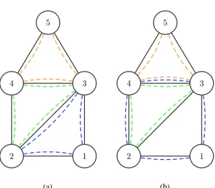
The deployment strategy used by SHEAR is based on the observation that finding a maximal set of fundamen-tal cycles—cycles which form a basis out of which all other cycles can be constructed through combinations— can be done efficiently: every graph G= (E,V) has
1 2 3 4 5 (a) 1 2 3 4 5 (b)
Figure 1: Example of two fundamental cycle bases of a graph: one consisting of “minimal cycles” and one with overlaps.
Algorithm 1 SHEAR Deployment
1: given networkG
2: T ←G
3: S←/0
4: while (T not loop-free)do
5: for allconnected componentCinT do
6: B ←cycle basisofC
7: while B6=/0do
8: selectmost frequent elementv∈B
9: S←S∪v
10: removevfrom T
11: removeall cycles containingvfrom T
12: return S
at least one set of |E| − |V|+1 fundamental cycles, henceforth calledcycle basis. Every cycle in Gcan be represented as a linear combination of the fundamental cycles of a cycle basis. Such a set of fundamental cycles is called a fundamental cycle basis, and a single graph can have multiple different bases. The concept of a fundamental cycle basis is demonstrated in Figure 1.
To obtain a cycle basis, SHEAR computes a spanning tree; each edge not in the spanning tree will define one fundamental cycle. Given a cycle basis, Openflow switches are then deployed iteratively and in a greedy manner, first replacing the node participating in the maximum number of cycles (ties broken arbitrarily). The resulting graph is tested for loops, and if the tree decomposition is not achieved yet, the next cycle basis is computed iteratively. A listing of the algorithm appears in Algorithm 1.
An example for tree decomposition is shown in
(a) (b)
Figure 2: Example for tree decomposition. The redun-dantly connected graph (a), is decomposed into a tree
(b). The red nodes are the deployed Openflow switches.
Figure 2: A well-connected graph is given as an input to SHEAR, which is then decomposed into a cycle-free graph by designating 5 nodes (out of 17) as Openflow nodes. In this example, the decomposition results in a single legacy Ethernet connected component: a tree.
B. Hybrid Data Plane
The tree decomposition results in a set of loop-free
fragments: one or more “legacy” Ethernet connected components, and a set of nodes designated as Openflow switches (which may not be directly connected).
These fragments are the building blocks for SHEAR: in order to compute end-to-end paths, SHEAR stitches the fragments together to form paths. For scalability concerns, SHEAR also allows to further subdivide frag-ments into smaller broadcast domains, using VLANs (“Panopticon as a service” over SHEAR). Concretely, as we will see, SHEAR uses VLANs for two pur-poses. First, in order to improve scalability and preserve Ethernet semantics. And second, in order to connect Openflow switches to each other, and to define and multiplex resp. demultiplex so-calledpathlets: path seg-ments (broadcast domains) in a given loop-free frag-ment. We require that every access node participates in at least one VLAN, and Openflow switches support all incident VLANs. Pathlets are stitched together at Openflow switches, using VLAN re-tagging.
In the following, we will describe the three different steps in more detail: (i) extracting path diversity, (ii)
stitching together pathlets, and (iii) providing network services with Ethernet semantics.
Extracting path diversity. The tree decomposition results in loop-free components, and no path selection flexibility is left: essentially, the path diversity has been extracted from the legacy network and assigned to the Openflow nodes. We define two Openflow nodes as neighbors if they are connected to the same legacy connected component. In order to be able to exploit the path diversity, we define edge-disjoint pathlets be-tween neighboring Openflow nodes; we want to create
a maximal number of pathlets between every pair of neighbors. Since the data plane is hybrid, the pathlet is identified by asource-port, VLAN tag pair: as there is only one path in a given connected component between two ports of neighboring nodes, the source port defines the path and the VLAN tag defines the destination (the intended Openflow switch). An interesting side-effect of our cycle-breaking approach, is that VLANs can be reused by different pathlets even in the same connected component (as long as the pathlets do not traverse a common legacy switch). Consequently, the full path diversity of the original network is maintained by the pathlets, and there are no forwarding loops.
Stitching pathlets. If two Openflow nodes are not neighbors, paths between them can be created by stitch-ing pathlets (VLAN and source port pairs) together, i.e., by concatenating pathlets between successive pairs of neighbors. It is possible to stitch pathlets into edge-disjoint paths between any pair of Openflow nodes (and one of the paths must be the shortest path between the nodes). While local to a connected component, pathlets can be used to create network-wide edge-disjoint paths: pathlet stitching enables us to extract the path diversity globally.
Network service with Ethernet semantics.Ethernet networks depend on VLANs to segment the network into broadcast domains. When two hosts in different VLANs need to communicate, traffic must be forwarded between VLANs. While this is not possible with pure Ethernet switches because VLANs have a global mean-ing, for SHEAR, VLAN tags have a meaning local only to a connected component: swapping VLAN tags is not only technically possible, it is required (when describing pathlet stitching, VLAN tag swapping was used). If source and destination hosts are in the same VLAN and in the same connected component, traffic will always be forwarded directly: both communication partners are in the same broadcast domain. Therefore, SHEAR only kicks in if either the hosts are in different VLANs, or in different connected components. While this may at first glance seem as an impediment for the implementation of SHEAR, it is common practice to segregate hosts in different VLANs in current LANs and enterprise networks. In order for a host to be serviced by SHEAR, every Openflow node in the connected component must have at least one port connected to the host’s VLAN (all nodes in order to enable SHEAR access to all possible edge-disjoint paths).
C. Hybrid Control Plane
In order to ensure a high availability, SHEAR must:
(a) monitor the availability of all the pathlets between neighboring Openflow nodes, (b) monitor all the paths between access nodes (where hosts are connected) to
the Openflow nodes in the same connected component, and(c) in case of traffic affecting failure, re-route the traffic in a timely manner. As we will see,(a) and (b)
can be achieved automatically and in a reactive manner, instrumenting theSpanning Tree Protocol (STP)(or any legacy shortest path protocol).
Generally, since pathlets can traverse multiple hops in a legacy connected component, SHEAR must have some visibility into the state of the legacy connected components. In addition, users will most probably be connected through a legacy access node, therefore monitoring of the paths between access switches to Openflow nodes is also necessary. SHEAR leverages the distributed control plane protocol used by Ethernet networks, namely MSTP.
Leveraging MSTP in SHEAR. Every legacy node in a connected component sends MSTP messages (BP-DUs) through all interfaces not configured as interfaces connected to hosts. Every BPDU carries the following information, for each spanning tree instance: the ID (MAC address) of the spanning tree root, and the cost of the path to root. In general, since STP is a variant of a distance vector protocol, the cost of the path to the root converges to the cost of the shortest path. As in SHEAR legacy connected components do not have cycles, every BPDU carries with it information on the availability of the path to the root: if there is a failure on the path between a spanning tree root and a port of an Openflow node, the value of the root ID in the BPDUs will change. Therefore, any failure in the path between a spanning tree root and an Openflow node can be detected by examining the contents of a BPDU.
Moreover, since any failure will change the value of a root in the BPDU, SHEAR can localize the failure in the segment between the expected root and the current root. Therefore, for a single edge failure, if following a failure the newly elected root will be adjacent to the failed edge, SHEAR can localize the failure immediately upon detection. When configuring MSTP, it is possible to set a root priority value for every MSTP node. Therefore, by assigning root priorities in a monotonously increasing fashion from the root to an Openflow node, it is possible to guarantee that for any single edge failure, the failure will be localized.
As MSTP is based on RSTP (where multiple in-stances of RSTP use the same BPDU), an update BPDU is triggered immediately upon detection of a change in a spanning tree instance: either by a node detecting a failure of the edge leading to the root, or by a change in the value of the root. In Section V, we show that the time it takes for a change in a spanning tree to propagate by MSTP to an Openflow node, is in order of 100 ms. After detecting the failure, the centralized controller can immediately localize the failure, and then performs
two tasks: (i) re-route all affected traffic around the failure (if possible), and (ii) notify the network op-erator about the failure. SHEAR avoids the normal (distributed) protocol reconvergence by imposing the controller’s failover and rerouting mechanism: this is not only faster, but given our tree decomposition, also provides a more flexible selection of paths (stitching together the pathlets). As the centralized controller is aware of all the installed paths (flow table entries) whose traffic is affected by the failure, it can immediately compute new paths around the failure if such paths exist. This capability is unparalleled by any packet switching system, apart from MPLS-TE with FRR (which is cumbersome to plan and configure). In addition, the ability to notify the network operator about a failure and its location, is unmatched in enterprise networks without the use of specialized network management systems and configuration of SNMP traps in all nodes.
Spanning Tree Embedding.In general, the spanning tree embedding problem can be seen as an interesting new variant of network tomography problems, where placeable endpoints can only observe shortest distances to certain “beacons”: the STP roots. While comput-ing the minimal number of spanncomput-ing trees ensurcomput-ing this property can be computationally hard in general, ensuring detectability given the resulting trees of the Openflow node deployment computed by SHEAR is easy, as we will see in the following. LetT be a tree decomposition. We first extend the decomposition T to include all edges of G (recall that some of them are missing due to the Openflow switch removal): the trees T ∈T can be completed arbitrarily with these missing links, resulting in set T∗. We then proceed tree by tree. Let T∈T∗ be an arbitrary tree. In order to ensure that each physical link occurs on at least one shortest path between a spanning tree root (the beacon) and an Openflow switch (the observability point), we embed ` many spanning trees on T, where ` is the number of leaves ofT; each spanning tree is rooted at a different leaf. If there are no leaves inT (e.g., a line with Openflow nodes at both edges), then we embed a single spanning tree rooted at an arbitrary node (preferably as far away as possible from all the Openflow nodes).
This approach for placement of spanning tree is the opposite of current best practices and conceptions about spanning tree embedding: in SHEAR we place the roots as far as possible from the Openflow nodes, while current best practices say to place the roots as near as possible to the Openflow nodes.
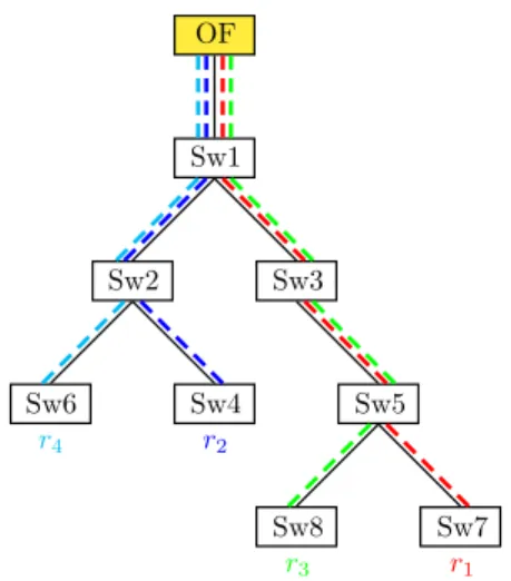
Example. In order to give an example, consider Figure 3: the figure shows one tree of the tree decompo-sition. Since the tree has`=4 leaves, it is sufficient to place a single observability point (Openflow node) (at the tree root), and embed four spanning trees, with one
Sw1 Sw2 Sw3 Sw4 Sw5 Sw6 Sw7 Sw8 OF r1 r2 r3 r4
Figure 3: Example: One component of the tree decom-position. By placing one Openflow switch at the root and by embedding four spanning trees, with one root per leaf, it is ensured that each link occurs on a shortest path between a root and the Openflow switch, facilitating fast detection.
Algorithm 2 SHEAR Tree Embedding
1: compute T∗ fromT
2: for allT ∈T∗do
3: letvbe T’s Openflow switch
4: for all leafw∈T do
5: embed STP inT, rooted atw
6: monotonically order IDs along the path
7: if T has no leavesthen 8: choose a nodew∈T
9: monotonically order IDs along the paths in every direction
root per leave. The resulting tree embeddings have the property that each link occurs on at least (in this case: exactly) one shortest path between one of the roots and the Openflow node.
While the algorithm described so far is good enough for the fastdetection of failures, SHEAR uses a trick to even support a fast localization: by ordering the IDs between a root and a switch in a monotonically increasing order, the new root after a failure implicitly provides information onwherea link failure took place. Note that the monotonic order also ensures a very fast reconvergence: the link failure triggers a BPDU, and the new root immediately propagates through the network to the Openflow switch, without encountering a competing root candidate.
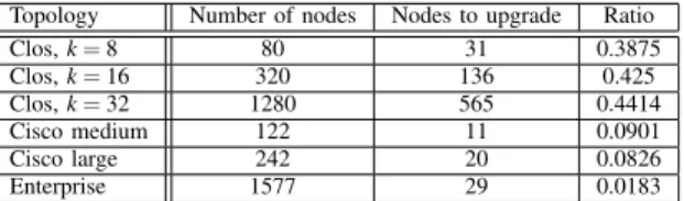
Topology Number of nodes Nodes to upgrade Ratio Clos,k=8 80 31 0.3875 Clos,k=16 320 136 0.425 Clos,k=32 1280 565 0.4414 Cisco medium 122 11 0.0901 Cisco large 242 20 0.0826 Enterprise 1577 29 0.0183
Table I: Number of nodes to upgrade for different topologies
IV. Simulations
We use extensive simulations to study the deployment cost and scalability of SHEAR. In the following, we will first focus on the number of to-be-deployed Open-flow switches in order to achieve the desired loop-free network decomposition, in different synthetic and real enterprise networks. Second, we well also consider the resource requirements of SHEAR in terms of VLANs. For comparison, we will use the same methodology and simulation environment as used in prior work in [10]. In particular, while SHEAR has a different objective and provides less SDN functionality than Panopticon, for the sake of comparison, we consider a simulation scenario where all traffic is waypoint-enforced, through Openflow switches, using VLANs. Interestingly, as we will see, SHEAR’s deployment strategy outperforms the one by Panopticon even in this case.
A. Scalable Deployment
We study how many Openflow switches are needed to decompose a network into trees. We implemented the tree decomposition algorithm using a python program which accepts a graph (ingraphmlformat) and returns a list of nodes to be upgraded to Openflow switch. The program uses theNetworkXlibrary for computing the cycle basis of graphs (and to readgraphmlfiles).
We consider six different topologies: 1) Three syn-thetic data center oriented topologies: essentially fat-tree resp. Clos topologies of different sizes. 2) Two Cisco recommended enterprise topologies [3]. 3) A private large scale campus network (topology of a real network).
We would intuitively expect that the deployment cost will depend on the connectivity and density of the underlying network.
We begin by exploring the well-known, highly con-nected fat-tree (or Clos) topology [9]. The fat-tree is a three tiered topology, where for a topology with 5k24 nodes: k22 nodes are located at the lowest tier (access), k22 nodes are located at the medium tier (aggregation/distribution), and k24 nodes are located at the highest tier (core). We therefore expect that SHEAR will need to upgrade around 40% of the nodes:
choosing to upgrade all the aggregation nodes is an obvious solution. We show the results for three instances of fat-tree, with k=8,16,32, in Table I: the values are close to the expected 40%, fork=8 the result is slightly better than 40%, and fork=16,32 the results are slightly worse.
However, the vast majority of enterprise and campus networks are not fat-tree based: they do not have to provide full bisection bandwidth, and are less-well connected. We therefore next explore a second syn-thetic topology: Cisco’s recommended high availability campus network topology [3]. This topology is also 3-tiered, where the number of core nodes is 2 and the number of aggregation nodes is a fraction of the number of edge nodes. We generated two synthetic topologies based on Cisco’s recommendations, one with 100 edge nodes and one with 200 edge nodes. For both instances we chose the ratio of aggregation nodes to edge nodes to be 1 : 5. Again, as upgrading all the aggregation nodes is a valid solution, we expected a roughly 20% deployment (due to the 1 : 5 ratio). The results as seen in Table I are lower: SHEAR needs to upgrade only half of the aggregation nodes in order to remove all cycles, that is, less than 10% of the nodes need to be upgraded. These solutions do not partition the topologies into multiple connected components.
While Cisco’s recommendation may be considered as best practice, many networks do not adhere to these recommendations. While topologies of real networks are not easy obtain, we have access to the topology of a large enterprise network, comprised of 1577 nodes. For the large enterprise network, SHEAR needed to convert only 29 nodes to Openflow switches (Table I): this is less than 2% of the nodes.
B. Resource Constraints
In order to study the resource requirements of SHEAR in terms of VLANs and flow table entries, we use the following methodology. We use traffic ma-trices from theLawrence Berkeley National Laboratory
(LBNL) [15] traces. The LBNL data represents over 100 hours of anonymized packet level traces depicting the activity of several thousand internal hosts. The traces are aggregated according to source-destination pairs, and contain sources from 22 subnets. For every edge node in a topology (edge nodes are defined as nodes which have hosts connected to them), we choose in a random round-robin fashion a subnet from the LBNL data to associate. We choose one node in the topology (which is not an edge node), to function as the gateway to outside networks. All traffic to hosts outside of LBNL’s 22 subnets are associated with the node chosen as the gateway. The resulting traffic matrix is then projected unto the topology, using the shortest paths between
source-destination pairs in order assign loads to edges (links). In order to make sure that traffic matrix can be satisfied by the topology, we conservatively scale the load generated by the traffic matrix so that the highest loaded edge has 50% utilization.
For the purpose of comparability with Panopti-con [10], we Panopti-consider an extension of SHEAR where traffic between communicating ports is waypoint-enforced, i.e., always needs to be routed via an Open-flow switch. Concretely, similarly to [10], we use VLANs to connect ports to waypoints. After placing the Openflow switches and projecting the traffic matrices, we can quantify the effect of system parameters on the viability and performance of our architecture. Of main interest are the number of VLANs used in a con-nected component (from each communicating port, one VLAN is used to connect it to all reachable Openflow switches [10]). These parameters represent limitations of network equipment: the number of VLANs supported by Ethernet switches.
In order to highlight this point and to make a fair comparison to Panopticon, for both architectures we upgrade the same number of nodes. The comparison is also interesting because radically different approaches are used for deployment: while Panopticon’s deploy-ment strategy depends on the specific traffic matrix, SHEAR is traffic-agnostic and only depends on topo-logical properties—an attractive property for long-term planning.
In the following, we will focus only on the real enterprise topology, and for every combination of pa-rameters (number of VLANs per connected component, number of flow table entries per switch), we generate 20 different traffic matrices by using different random seeds for the projection of the LBNL data on the topology. For both SHEAR and Panopticon, we allow 29 nodes to be upgraded.
Impact of VLAN constraints. According to IEEE 802.1Q, the maximum number of VLANs available is 4094: the VLAN tag space size is 12bit, and two tags are reserved. However, there are many enterprise network switches which in practice support much less for simul-taneous use. Therefore it is important to understand the required number of VLANs per connected component. For comparison with SHEAR we consider two versions of Panopticon: the volume-based deployment strategy
VOLwhich connects each port toalldirectly reachable Openflow switches, and the more scalable variantVOL2f
which connects a port only to two switches (see [10] for details); VOL2f relaxed resource constraints along the paths in the connected component, but comes at the price of forcing the traffic to use longer (less efficient) paths through the network.
We are interested in the question of how many ports
can be supported, i.e., routed by SHEAR, subject to resource constraints. The simulation results are seen in Figure 4 (a), where for every strategy three lines are plotted: the average percentage (solid line), minimal percentage (dashed line) and the maximal percentage (dotted line). Clearly, Figure 4 (a) shows that SHEAR is not limited by the number of VLANs: 32 VLANs were sufficient to provide afull coverage of the entire network (using only 29 Openflow switch). In addition, the different traffic matrices have a negligible effect on SHEAR (even for 16 VLANs the maximal and minimal coverage are almost the same). As only 32 VLANs are needed, there is no connected component which needs more than 32 spanning tree instances (MSTP can be used). For comparison, Panopticon is severely limited by the VLANs, and fares much worse: (1) the default implementation (VOL) needs 1024 VLANs to get close to full coverage (the minimal coverage at this point is about 90 percent); (2) even the implementation tweaked for using less VLANs (VOLf2) while on average getting close to full coverage with “only” 512 VLANs, never gets full coverage, and (3) different traffic matrices have a significant effect (even though every solution of
VOLandVOLf2 is trying to optimize the hybrid SDN according to the traffic matrix).
Recall that, due to the loop-free decomposition, SHEAR generally supports arbitrary forwarding paths. Therefore, when applying waypoint enforcement, flex-ibilities may be lost. However, as we will see, using SHEAR’s deployment strategy, flexible paths can be maintained even in the waypoint-enforced scenario of Panopticon: Figure 4 plots the results for the average stretch (for every traffic matrix an average stretch value was computed) for SHEAR and Panopticon (the de-fault implementation VOL). The result show that for SHEAR:
• There is no significant trade-off between the num-ber of VLANs and the average stretch.
• SHEAR traffic routing capabilities are very close to optimal. SHEAR is not optimal almost exclu-sively for traffic which goes through a single Open-flow switch (where the direct distance is shorter than the sum of the distances from the source and the destination to the Openflow switch). Even when measuring the 99th percentile stretch (not shown), at 64 VLANs the maximal stretch is 1: for at least 99% of the traffic the paths are optimal.
On the other hand, the stretch for Panopticon grows with the number of VLANs (which means the stretch grows with the SDN coverage), and is much larger than for SHEAR for most of the range.
16 64 128 256 512 1024 number of VLANs 0.1 0.2 0.3 0.4 0.5 0.6 0.7 0.8 0.9 1.0 SDN coverage
SDN coverage as a function of VLANs used
SHEAR
VOL
VOLf2
(a)16128256
512
1024
number of VLANs
1.010
1.015
1.020
1.025
SHEAR: Averagestretch
avg
max
min
(b)16128256
512
1024
number of VLANs
1.00
1.05
1.10
1.15
1.20
1.25
1.30
1.35
VOL: Averagestretch
avg
max
min
(c)Figure 4: Top: Comparison of required number of VLANs to upgrade a given percentage of the ports to SDN. SHEAR inblue, Panopticon ingreenandblack.Bottom:Comparison of the stretch: SHEAR on theleft, Panopticon on the right.
V. Prototype Implementation
We implemented a small prototype of SHEAR and ran experiments in our Openflow testbed.
A. Implementation and Testbed
We implemented the SHEAR controller based on the RYU platform. As our legacy network is based on the MSTP protocol, we only had to implement a parser for MSTP BPDUs: unlike OSPF, a switch sends its MSTP BPDUs through all the ports which are not defined as access ports: the controller can listen to MSTP without actively participating in the protocol. We also implemented the logic required for localization of failures (for our topology), and for re-routing traffic around failures (if an alternative path is available).
Our testbed is comprised of Cisco 3550, Cisco 2960, and Cisco 2950 switches (nodes 1-7). The 2950 switches use an old firmware version (circa 2004) supporting pre-standard MSTP (the legacy network uses a mix of standard and pre-standard MSTP
implementa-tions). We use one NEC IP8800 Openflow switch to em-ulate three SDN nodes, in order to (i) have path diversity and (ii) listen to MSTP messages at multiple locations. The topology hosts two spanning tree instances (using MSTP), with one instance rooted at node 3 and the second rooted at node 7. We used a server with multiple NICs to emulate 4 hosts (each emulated host has a dedicated NIC, and running a separate VM). All the links in the networks are Gigabit Ethernet links.
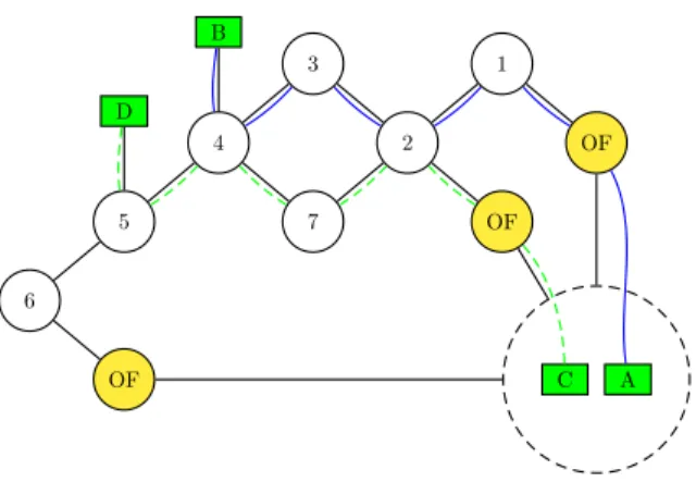
Recall that the SHEAR architecture decomposes the network into connected, undirected, and loop-free components: topological trees or even linear chains. However, for the prototype we choose to use a topology with a single simple cycle, as it allows us to compare failure recovery times with MSTP. The topology of the prototype network is shown in Figure 5. This topology can be converted to a chain by disconnecting node 7.
B. Failure Detection
In terms of performance, we are interested in the
de-1 2 3 7 4 5 6 OF OF OF B D A C
Figure 5: Testbed topology. Nodes 1−7 are Ethernet switches (the legacy “island”). The paths between hosts A-B and C-D use 2 different spanning trees rooted at nodes 3 and 7 respectively.
tecting a failure (at the Openflow switch observing the BPDU), communicating the event to the SHEAR controller, algorithmic failover path selection, new flow installation and eventually forwarding along the new routes. As failover paths often need to respect policies and capacities, computing good failover paths is an algorithmically hard problem. We hence assume that failover paths have been precomputed (but not signaled) by the controller. This mode of operation is very com-mon in systems requiring fast reaction times.
We distinguish between two types of SHEAR chain topologies: (i) one where there is a single Openflow switch at one end of the chain, and (ii) one where there are two Openflow switches at both ends of the chain. For the first type, a failure in the legacy connected component results in unreachability. For the second type, a single failure in the legacy connected component may not result in disconnections (assuming there is some path between the two Openflow switches outside of the connected component).
Due to issues pertaining mainly to clock synchroniza-tion between the switches and the SHEAR controller, for the first type it is not feasible to measure the time between the occurrence of a failure, and the detection of the failure by the SHEAR controller. However, for the second type, by re-routing traffic after the detection (and localization) of a failure, it is possible to accurately measure the time between the occurrence of a failure and the switch-over of traffic to an alternative route (by measuring in a single host the time during which no traffic arrives).
We disconnect node 7 of the topology, and generate traffic between hosts A and B. The traffic is generated
SHEAR1 SHEAR2 0.00 0.05 0.10 0.15 0.20 t [sec]
Recovery Time - Line
SHEAR1 SHEAR2 0.15 0.20 0.25 0.30 0.35 0.40 0.45 t [sec]
Recovery Time - IPERF
SHEAR MSTP1 MSTP2 0.0 0.5 1.0 1.5 2.0 t [sec]
Recovery Time - Cycle
Figure 6:Left:Ping switch over time for failures 2 hops (left) and three hops (right) from the Openflow switch.
Middle: IPERF switch over time for failures 2 hops
(left) and three hops (right) from the Openflow switch.
Right:Ping switch over time for failures 3 hops from an Openflow switch for SHEAR (left) and MSTP (right).
by sending ICMP echo request messages (ping) from A to B, at frequency of 100 messages per second (approximately 0.01s between consecutive messages). The default route used nodes 1,2,3,4. Link failures are induced on edges 3−4 and 3−2, which are 3 and 2 hops from the nearest Openflow switch respectively.
We usewiresharkto record all the incoming traffic to host B, and measure the gap between receivedping
messages. The results of these measurements, depicted in Figure 6 (left), show that the time to detect a failure and re-route the traffic is about 0.1 sec. Further than that, the results show that (as can be expected) the closer the failure is to an Openflow switch the sooner it is detected.
We assume that most of the measured unreachability time can be attributed to the failure detection phase. This assumption is corroborated by the difference in the average times between the two failure scenarios, as one additional hop translates to about 0.03son average.
C. Fast Failover
After measuring the time it takes to perform failover switching (re-route the traffic after detecting a failure), we proceed to check how the time we measured can be translated to common network applications, and how it compares to failover times of current techniques.
Failover times with TCP.As most network applica-tions are based on TCP, we perform measurements for the linear chain topology with the traffic being generated by IPERF. The results are shown in Figure 6 (middle). The restoration time for IPERF is significantly longer than measured with ping, as it is dictated by TCP’s retransmission timeout. The effect of the exponential backoff can be seen by comparing the restoration time 3 hops away to that 2 hops away (all the measured time were near to the extremities).
Baseline Comparison. As it is not possible to use a L2 restoration scheme in a line topology, it should be compared to protocols such as VRRP 2. As the
restoration time is around 100 ms, it is significantly better than VRRP (where in default settings around 3 secs are needed). Also of note, the distance from an Openflow switch affects the restoration time (and the variation of measured times) in about 30 ms for a difference of one hop.
In order to compare our results to that of state of the art L2 restoration schemes we used a topology which includes a cycle. Note that such a topology is not a pos-sible result of the SHEAR node placement algorithm, but the fault detection and localization techniques for SHEAR work just as well for this topology. For the topology containing a cycle, we use MSTP as a L2 restoration mechanism (SHEAR itself uses MSTP in the legacy network to detect failures).
We measured the (ping) time for two link failure scenarios using two different VLANs and Spanning Trees for every pair of hosts (the connections between hosts were edge disjoint as seen in Figure 5), using two symmetric edges of the cycle. The results depicted in Figure 6 (right) show the failover time as measured with the ping methodology for two failure scenarios (only one shown for SHEAR). The performance of SHEAR is as it was for the line (as expected), however the performance of MSTP is an order of magnitude worse.
VI. Related Work
There exists a wide consensus that the transition to SDN will be incremental [7], [10], [11], [19], and that hybrid networks posses practical importance [13]. However, reaping SDN benefits in partial deployments is non-trivial. Today, only very little is known about how to design and operate hybrid SDNs [19], and researchers have only started studying the deploy-ment [10], [19], and traffic engineering [1] challenges of such networks. The Panopticon architecture [10] uses a waypoint enforcement approach to implement a logical SDN abstraction, and hence support existing SDN control applications also in hybrid networks. In contrast to Panopticon, SHEAR does not aim to turn the network into an SDN (and does also not require waypoint enforcement), but uses the Openflow switches to render a given network more robust and flexible. However, as we have argued in this paper, SHEAR can be used to improve Panopticon itself: SHEAR’s deployment strategy is not only more cost efficient, but also facilitates a much more flexible and simple traffic engineering. Given these flexibilities, in contrast to Panopticon which was meant as an intermediate step until full SDNs become available, we understand
SHEAR as a long-term solution.
In terms of robustness and fast failure detection, SHEAR complements a range of actively discussed
works (see also [17] for a more general survey). Outages to link failures are not uncommon today, and we are not the first to observe the benefits of using multiple span-ning trees [4], [6], [12], [14]. In particular, Viking [6] implements a reliable Ethernet and fast failover using multiple spanning trees (however, without implement-ing a programmable network and fine-grained traffic engineering). There also exists an interesting proposal to improve failover times reconvergence (namely IGP) as a backup [18]. SHEAR shows that a controller-managed failover can be faster and more informed. Indeed, SHEAR assumes an interesting new position in the space of robust architectures as it combines data plane mechanisms (namely for the fast failure detection) and control plane mechanisms (namely for fast and more flexible failover).
VII. Conclusion
This paper proposed a novel network architecture which uses a small set of Openflow switches as cycle breakers and observability points to enable a more flexible traffic engineering and fast failover. SHEAR is purely reactive and light-weight, and does not require any expen-sive state polling mechanisms or the manual setup of (SNMP) traps. It nicely complements ongoing research on the control plane [8].
We believe that SHEAR is of interest beyond the Eth-ernet use case. For instance, IP-based networks without out-of-band control may benefit from the replacement of a subset of IP routers using (cheaper) Openflow switches. Note that all which is needed for SHEAR to be able to detect failures is information about short-est distances to certain special “beacon” points. Thus, SHEAR may not only be used on top of STP, but also on top of IGP protocols, such as OSPF.
Our work opens interesting directions for future re-search. For instance, it will be interesting to study whether Openflow local fast failover mechanisms could be used in addition to the centralized failover scheme, to further increase the network availability by offloading functionality to the data plane: due to the local view and the partial deployment, this is however a non-trivial extension [2], [16], [18]. Generally, we believe that our work sheds an interesting new light on the question of how to split functionality between control and data planes as well as between legacy and SDN protocols [7], [10], [11], [19], and can nourish the ongoing discussion.
Acknowledgments. We would like to thank Marco Canini, Dan Levin, and Sebastian Lohff for many dis-cussions, as well as our shepherd Volker Hilt. Research partially supported by the European Institute of Inno-vation & Technology (EIT) project Software Defined Networking project (13153).
References
[1] S. Agarwal, M. Kodialam, and T. V. Lakshman. Traffic
Engineering in Software Defined Networks. In
INFO-COM, 2013.
[2] M. Borokhovich, L. Schiff, and S. Schmid. Provable data plane connectivity with local fast failover: Introducing
openflow graph algorithms. In Proc. ACM HotSDN,
2014.
[3] Cisco. Campus Network for High Availability Design Guide, 2008. http://bit.ly/1ffWkzT.
[4] A. De Sousa. Improving load balance and resilience
of ethernet carrier networks with ieee 802.1s multiple spanning tree protocol. InInternational Conference on Systems, 2006.
[5] G. Even, J. (Seffi) Naor, B. Schieber, and M. Sudan. Approximating minimum feedback sets and multi-cuts in directed graphs. Algorithmica, 20(2):151–174, 1998. [6] M. Golash. Reliability in ethernet networks: A survey
of various approaches. Bell Labs Technical Journal,
11(3):161–171, Fall 2006.
[7] R. Hand and E. Keller. Closedflow: Openflow-like
control over proprietary devices. InProc. ACM HotSDN, 2014.
[8] C. Jin, C. Lumezanu, Q. Xu, Z.-L. Zhang, and G. Jiang. Telekinesis: Controlling legacy switch routing with
openflow in hybrid networks. In Proc. 1st ACM
SIG-COMM Symposium on Software Defined Networking Research (SOSR), pages 20:1–20:7, 2015.
[9] C. E. Leiserson. Fat-trees: universal networks for
hardware-efficient supercomputing. Computers, IEEE
Transactions on, 100(10):892–901, 1985.
[10] D. Levin, M. Canini, S. Schmid, F. Schaffert, and
A. Feldmann. Panopticon: Reaping the benefits of
incremental sdn deployment in enterprise networks. In
USENIX Annual Technical Conference (ATC), 2014. [11] H. Lu, N. Arora, H. Zhang, C. Lumezanu, J. Rhee, and
G. Jiang. Hybnet: Network manager for a hybrid network
infrastructure. InProc. ACM/IFIP/USENIX Middleware
Industry, 2013.
[12] G. Mirjalily, F. Sigari, and R. Saadat. Best multiple
spanning tree in metro ethernet networks. In
Confer-ence on Computer and Electrical Engineering (ICCEE), volume 2, pages 117–121, 2009.
[13] ONF. Hybrid Working Group. http://bit.ly/Lu4XOw. [14] M. Padmaraj, S. Nair, M. Marchetti, G. Chiruvolu, and
M. Ali. Traffic engineering in enterprise ethernet with
multiple spanning tree regions. InSystems
Communica-tions, pages 261–266, 2005.
[15] R. Pang, M. Allman, M. Bennett, J. Lee, V. Paxson,
and B. Tierney. A first look at modern enterprise
traffic. In5th ACM SIGCOMM Conference on Internet
Measurement (IMC), 2005.
[16] L. Schiff, M. Borokhovich, and S. Schmid. Reclaiming the brain: Useful openflow functions in the data plane. InACM Workshop on Hot Topics in Networks (HotNets), 2014.
[17] M. Steinder and A. S. Sethi. A survey of fault
local-ization techniques in computer networks. Science of
Computer Programming, 53(2):165 – 194, 2004. [18] O. Tilmans and S. Vissicchio. Igp-as-a-backup for robust
sdn networks. In 10th International Conference on
Network and Service Management (CNSM), 2014. [19] S. Vissicchio, L. Vanbever, and O. Bonaventure.
Op-portunities and Research Challenges of Hybrid Software
Defined Networks. ACM Computer Communication