APPLICABILITY & EFFECTIVITY
This manual provides instructions for the following FieldServer products: Description
FS-X20 Series FieldServer
FS-X30 Series FieldServer
FS-X40 Series FieldServer
Effective for all systems manufactured after April 2013
The instructions are effective for the above as of April 2005
Instruction Manual Part Number: T17003 Kernel Version: 6.10 Document Revision: 0
FieldServer Technologies 1991 Tarob Court Milpitas, California 95035 USA Web: www.fieldserver.com
TABLE OF CONTENTS
1 Utilities Overview ... 6
1.1 Ping Utility (RuiPing) ... 6
1.2 Remote User Interface (RuiNet) ... 6
1.3 Serial and Snapshot Capture Utility (RuiDebug) ... 6
1.4 FST_Diag Utility ... 6
1.5 Internet Address Configurator (RuiBoot) ... 7
2 PC Requirements ... 8
2.1 Hardware... 8
2.1.1 Connecting to a FieldServer over the Internet ... 8
2.2 Software ... 8
2.3 Installation and Setup ... 8
3 Installing New Firmware on a FieldServer ... 9
3.1 Using Winzip: ... 9
3.2 Not using WinZip: ... 10
4 Ping Utility (RuiPing) ... 11
4.1 Manually checking the network for Duplicate IP Addresses ... 11
5 Remote User Interface (RuiNet) ... 12
5.1 A – Connecting to a FieldServer ... 12
5.2 B - FieldServer Information ... 13
5.2.1 FieldServer Information – Settings Aspect ... 13
5.2.2 FieldServer Information – Status Aspect ... 14
5.3 P - Enable/Disable Password Protection ... 15
5.4 O - Connection Overview ... 16
5.4.1 Connection Overview – Settings Aspect. ... 17
5.4.2 Connection Overview - Status Aspect ... 18
5.4.3 Connection Overview - Statistics Aspect ... 19
5.4.4 Connection Overview - Error Statistics Aspect ... 21
5.4.5 Connection Overview - API Aspect ... 22
5.5 N - Node Overview ... 24
5.5.1 Node Overview - Settings Aspect ... 24
5.5.2 Node Overview - Status Aspect ... 25
5.5.3 Node Overview - Operating Statistics Aspect ... 26
5.5.4 Node Overview - Error Statistics Aspect ... 27
5.6 M – Map Descriptor Overview ... 28
5.6.1 Map Descriptor Overview - Settings Aspect ... 29
5.6.2 Map Descriptor Overview – Status Aspect ... 30
5.6.3 Map Descriptor Overview - Operating Statistics Aspect ... 30
5.6.4 Map Descriptor Overview - Error Statistics Aspect ... 31
5.7 A – Data Array Overview ... 32
5.7.1 Data Array Detail Screen ... 32
5.8 L – Message Log ... 33
5.9 E – Error Messages ... 33
5.10 F – Driver Messages ... 33
5.12 D – Download Configuration to FieldServer ... 34
5.12.1 Procedure for Downloading a File from a PC to a FieldServer ... 34
5.13 U - Upload Configuration from FieldServer ... 35
5.13.1 Procedure to Upload a File from a FieldServer to a PC ... 35
5.14 I - Change IP Address ... 35
5.14.1 Procedure to Change a FieldServer’s IP Address ... 36
5.14.2 Obtain the IP address using the DHCP Client ... 36
5.14.3 Obtain the IP address using the FieldServer’s DHCP Server ... 37
5.15 K - Change UI Display Mode ... 38
5.16 Restart FieldServer ... 39
6 Serial and Snapshot Capture Utility (RuiDebug) ... 40
6.1 Log a Serial Port ... 40
6.2 Monitor a FieldServer ... 40
7 FST_Diag ... 41
7.1 Using the FST_Diag ... 41
7.1.1 Options – Return IP address ... 42
7.1.2 Configuring the “Log Type” List ... 43
7.1.3 Troubleshooting ... 43
7.1.4 Contents of Upload.zip ... 44
8 Internet Address Configurator (RuiBoot) ... 45
8.1 The INI file ... 45
Appendix A. Troubleshooting ... 46
Appendix A.1. General Configuration ... 46
Appendix A.2. File Download ... 46
Appendix B. Command Line Switches ... 47
Appendix B.1. Ping Utility Command Line Switches ... 47
Appendix B.1.1. Ping FieldServer by IP Address -i<ip_address> ... 47
Appendix B.1.2. Ping FieldServer by Name -n<FieldServer_Name> ... 47
Appendix B.1.3. Ping FieldServer by Hot Standby Pair Name -p<Pair_Name> ... 47
Appendix B.1.4. Ping list of FieldServers from file -f<filename> ... 47
Appendix B.1.5. Set ping repeat rate -r<seconds> ... 48
Appendix B.1.6. Use Quiet Mode-q ... 48
Appendix B.1.7. Use Analyze Mode -a<filename> ... 48
Appendix B.1.8. Display FieldServer Identification Number -b ... 49
Appendix B.1.9. Display FieldServer Hot Standby Pair Names -c... 49
Appendix B.1.10. Display FieldServer Ethernet ID -e ... 49
Appendix B.1.11. Do not display heading -0 ... 49
Appendix B.1.12. Display N Network Ports ... 49
Appendix B.1.13. Display Program Version -v[e] ... 49
Appendix B.1.14. Display Help -h ... 50
Appendix B.1.15. Display exit codes -x ... 50
Appendix B.1.16. Enable system error test exit codes -t<seconds> ... 50
Appendix B.1.17. Using RuiPing exit codes in a batch file ... 51
Appendix B.2. Ruinet Command Line Switches ... 52
Appendix B.2.1. Connecting to a FieldServer using IP Address -i ... 52
FieldServer Technologies 1991 Tarob Court Milpitas, California 95035 USA Web: www.fieldserver.com
Appendix B.2.4. The Most Recently Connected FieldServer -p ... 52
Appendix B.2.5. Disable Auto Connect Mode –m0 ... 52
Appendix B.2.6. Restart a FieldServer -b ... 52
Appendix B.2.7. Startup Screen -x ... 53
Appendix B.2.8. Transferring files –l, -f ... 53
Appendix B.2.9. Downloading Files –u0 ... 53
Appendix B.2.10. Uploading Files –u1 ... 54
Appendix B.2.11. Forcing a Download -o ... 54
Appendix B.2.12. Number of File Transfer Tries -n ... 54
Appendix B.2.13. Set FieldServer Side File Name for a transfer -f ... 54
Appendix B.2.14. Set Local File Name for a Transfer -l ... 54
Appendix B.2.15. Help -h ... 54
Appendix B.2.16. Create a Log File -a ... 55
Appendix B.2.17. Version Information -v, -ve ... 55
Appendix B.2.18. Skip date and time check on connect -m1 ... 55
Appendix B.2.19. Delete a File -z ... 55
Appendix B.2.20. Synch FieldServer Time with the Computer’s Time -g ... 55
Appendix B.2.21. Set Timeout -k ... 56
Appendix B.2.22. -downloadPassword xxxxxxxxxxxxxxxx ... 56
Appendix B.2.23. Run in Test Mode ... 56
Appendix B.3. Serial & Snapshot Capture Utility Command Line Switches ... 56
Appendix B.3.1. Target IP Address -i ... 56
Appendix B.3.2. Target FieldServer Name -y ... 57
Appendix B.3.3. Monitor a FieldServer by broadcast (unknown IP) -ib ... 57
Appendix B.3.4. Set self termination tim -q. ... 57
Appendix B.3.5. Version Information -v ... 57
Appendix B.3.6. Help -h ... 57
Appendix B.3.7. Change the default log file name -a ... 57
Appendix B.3.8. Echo to console -e ... 57
Appendix B.3.9. Listen Only (Suppress Snapshots) -s ... 58
Appendix B.3.10. Limit the log to recording errors only -r ... 58
Appendix B.3.11. Reset The FieldServer statistics and errors -x ... 58
Appendix B.3.12. Record driver messages in a special log -l ... 58
Appendix B.3.13. Set log Level -k ... 58
Appendix B.3.14. Take a single snapshot and terminate -n ... 58
Appendix B.3.15. Add Map_Descriptors to the snapshot -o ... 58
Appendix B.3.16. Log a serial port (P1..P8, R1/2) -z ... 59
Appendix B.3.17. Redirect Responses from FieldServer (Internet Logging) -m ... 59
Appendix B.4. RuiDebug interactive mode ... 61
Appendix B.5. Internet Address Configurator Command Line Switches ... 62
Appendix B.5.1. Single Shot vs. Continuous ... 62
Appendix B.5.2. Set Ethernet ID (Mac Address) -e ... 62
Appendix B.5.3. Serial Number -s ... 63
Appendix B.5.4. Listen Only -l ... 63
Appendix B.5.5. Force Overwrite -o ... 63
Appendix B.5.6. Version -v ... 63
Appendix B.5.8. Cache Timeout -q ... 63
Appendix B.5.9. Use Config file.-f ... 63
Appendix B.5.10. Set Log File -a ... 63
Appendix B.5.11. Log Level (Verbosity) -k ... 64
Appendix B.5.12. Allow old version of 8051BP03 to make boot request -x ... 64
Appendix B.6. Continuous Mode - Configuration Files ... 64
Appendix B.6.1. Continuous Mode - Menu’s ... 65
Appendix C. Reference ... 67
Appendix C.1. General Parameter Descriptions ... 67
Appendix C.1.1. Timeout Values ... 67
Appendix C.1.2. Probation delay ... 67
Appendix C.1.3. Multidrop mode ... 67
Appendix C.1.4. Inter character timeout (IC Timeout) ... 67
Appendix C.1.5. Data Caching ... 67
FieldServer Technologies 1991 Tarob Court Milpitas, California 95035 USA Web: www.fieldserver.com
1
UTILITIES OVERVIEW
1.1
Ping Utility (RuiPing)
The RuiPing Utility is used to:
Ascertain the existence of working FieldServers Monitor a FieldServer’s healthy system operation Check a FieldServer’s system information
1.2
Remote User Interface (RuiNet)
The RuiNet Utility is used to:
Transfer files (configuration, firmware, etc ) to and from a FieldServer Monitor a working FieldServer’s internal data and parameters Change or update a FieldServer’s internal data and parameters Delete files on a FieldServer
Change the FieldServer’s IP address Restart a FieldServer
1.3
Serial and Snapshot Capture Utility (RuiDebug)
The RuiDebug Utility is used to capture information about a FieldServer to assist in problem diagnosis. RuiDebug is useful for troubleshooting low-level serial communications when standard troubleshooting options have been exhausted. RuiDebug captures all data traffic on a given serial port in either hex or ASCII format in a log file which can be analyzed for inconsistencies by anyone familiar with the communications protocol in question. RuiDebug also captures information about the FieldServer being monitored in a separate log file (RuiDebug.log). The snapshot option available with RuiDebug also captures connection statistics in RuiDebug.log.
The information captured includes 1. FieldServer status Information 2. Connection Statistics
3. Error Messages 4. Data Array Contents 5. Port Logs
The RuiDebug Utility cannot capture a log of Ethernet based message contents.
1.4
FST_Diag Utility
The FST_Diag Utility connects to a FieldServer, collects information about the FieldServer setup and current processes, downloads the configuration, zips all information into one file and reports back to FieldServer support with the information.
The FST_Diag Utility cannot capture a log of Ethernet based message contents. Refer to Enote0063 on the supplied flash drive for information on how to do this.
1.5
Internet Address Configurator ( RuiBoot)
The RuiBoot application can be used to monitor the FieldServers on a LAN, automatically allocate IP addresses, alert the user to duplicate IP addresses and perform other Utility functions such as setting the MAC address of the Ethernet adapter on the FieldServer. This Utility is typically only required if advanced functions are needed or if old firmware that does not support IP change via RuiNet is being used.
FieldServer Technologies 1991 Tarob Court Milpitas, California 95035 USA Web: www.fieldserver.com
2
PC REQUIREMENTS
2.1
Hardware
The Utilities work over an Ethernet network and require a TCP/IP enabled PC with a network card supporting 10/100Mbit/s Ethernet. The PC and FieldServer can be connected via an established network or directly using a cross-over cable.
2.1.1
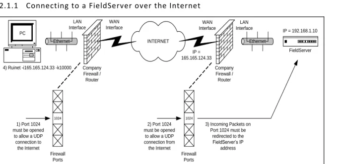
Connecting to a FieldServer over the Internet
INTERNET Company Firewall / Router PC Company Firewall / Router Ethernet Ethernet FieldServer 1024 Firewall Ports 1024 Firewall Ports LAN Interface WAN Interface WAN Interface LAN Interface 1) Port 1024 must be opened to allow a UDP connection to the Internet 2) Port 1024 must be opened to allow a UDP connection from the Internet IP = 192.168.1.10 3) Incoming Packets on Port 1024 must be redirected to the FieldServer’s IP address IP = 165.165.124.33 4) Ruinet -i165.165.124.33 -k10000
Figure 2.1 – Diagram showing Connection over the Internet Notes
1. The PC firewall must allow UDP connections to port 1024 on the WAN (Wide Area Network) interface/Internet.
2. The network firewall must allow UDP connections from the WAN interface/Internet to port 1024. 3. The network firewall must redirect network packets from port 1024 to the FieldServer’s IP address.
2.2
Software
The Utilities run under any of the following operating systems: DOS, Windows 95 (SP2 upwards), Windows 98, 2000, NT, XP
2.3
Installation and Setup
The utilities are loased on the flash drive shipped with the FieldServer. They can be accessed from the start menu once they have been downloaded onto the computer: |Start|Programs|FieldServer Utilities|
The Ruinet PC and the FieldServer have to be setup with an IP address on the same subnet .
The Ruinet PC’s TCP/IP settings may have to be changed to successfully connect to a specific FieldServer if there is more than one FieldServer on the network.
If a PC is used on an already established network, it is better to change the FieldServer’s IP address than the PC’s IP address. Please refer to section 5.14.1 to change the FieldServer’s IP address.
3
INSTALLING NEW FIRMWARE ON A FIELDSERVER
New firmware is supplied as a zip file called install.zip under special circumstances where a firmware update is required. It is not part of the standard shipment.
Open the install.zip file. This can be done directly from your mail client.
If you are using WinZip, press “Install”. Alternatively extract the files to a temporary folder and run the setup.exe program.
If there is only one FieldServer on your network, then the firmware install procedure will start automatically after pressing “Install”
If there are multiple FieldServers on your network, select the FieldServer that requires the new firmware to be installed from the menu shown.
To download a configuration file other than the one included in the Install.zip file do the following:
3.1
Using Winzip:
Rename the file you want to download to the FieldServer to config.csv Click on “Add”
FieldServer Technologies 1991 Tarob Court Milpitas, California 95035 USA Web: www.fieldserver.com .
Browse and Select the config.csv file you want to send to the FieldServer Click “Add”
Click “Install” to install the config.csv file to the FieldServer.
3.2
Not using WinZip:
Copy the config.csv file to the Install.zip Notes
The csv file to be added must be named config.csv
If the Install.zip file contains multiple csv files, only one will be downloaded to the FieldServer. If config.csv, primserv.csv and secdserv.csv are present then config.csv will be downloaded.
If config.csv is not present then primserv.csv will be downloaded and if config.csv and primserv.csv are not present then secdserv.csv will be downloaded.
4
PING UTILITY (RUIPING)
RuiPing is a Utility that “pings” a specific FieldServer or all FieldServers on the network. A ping is a general message that requests a reply from a FieldServer. The reply indicates the existence of a FieldServer on the network and contains information of use to the RuiPing operator or to batch files using RuiPing. FieldServers will respond to the ‘Ping’ application provided with Microsoft Windows, but there is no distinction between FieldServers and other devices that respond to the ping.
Run RuiPing from the Start Menu: Start|Programs|FieldServer Utilities|Ping Utility or using Run, Command, RuiPing -i1.2.3.4
The screen-shot below shows the typical layout of information presented by RuiPing:
Figure 4.1
RuiPing will continue pinging FieldServers every 3 seconds until the Q key is pressed or will exit when conditions specified by command-line switches have been met.
4.1
Manually checking the network for Duplicate IP Addresses
Connect the FieldServer to the network and run RuiPing. Verify that the IP address chosen for the FieldServer is active
Disconnect the FieldServer. Run the Windows Ping Utility (in DOS, type: ping <IP Address>). Make sure that nothing responds to the chosen IP address.
For further information on pinging specific FieldServers, refer to Appendix B. The FieldServer names
as specified under Bridge Title in the individual CSV files.
The IP addresses of the FieldServers on the network. In this case there are two FieldServers.
The * indicates that this FieldServer has a system error that can be viewed on the RuiNet Error screen.
The FieldServer’s Kernel version followed by the DCC version.
FieldServer Technologies 1991 Tarob Court Milpitas, California 95035 USA Web: www.fieldserver.com
5
REMOTE USER INTERFACE (RUINET)
The notes in this section explain how to navigate the menu system provided by RuiNet and provide information on the contents of the various screens.
5.1
A – Connecting to a FieldServer
Since RuiNet can only work with one FieldServer at a time, it is necessary to target the FieldServer of interest. (Note that it is possible to run multiple instances of RuiNet at the same time). If RuiNet is run without specifying a target it will provide a list of the FieldServers on the network. Pick the required FieldServer from the list -
Figure 5.1
If a FieldServer is not selected, RuiNet will wait about 10 seconds and then automatically connect to the FieldServer last connected.
Figure 5.2
List of other action keys. Some of these keys only work in Expert Mode.
Press one of these keys to select the option.
FieldServer Name. (Specified in ‘FieldServer, Title’ section of the CSV file).
Type “1“ to pick the first FieldServer or “2” to pick the second.
Password protection can be enabled to restrict access to data and prevent changes.
5.2
B - FieldServer Information
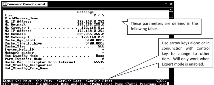
FieldServers were previously known as bridges, hence the use of the B key to access the screen displaying general information about a FieldServer. The B Screen consists of two aspects (settings and status). Use the spacebar to toggle between the two aspects. The settings screen is depicted below. The various parameters are described more fully in the tables that follow.
Figure 5.3 – FieldServer Information – Settings Aspect.
5.2.1
FieldServer Information – Settings Aspect
Parameter Description
Tier
FieldServers have the ability to run as “multiple” FieldServers on one platform. To differentiate between the different running applications, each of the applications is referred to as a Tier with a specific name. FieldServer_Name A name by which a FieldServer is identified - need not be unique. N1 IP Address The IP address of the N1 Ethernet Adapter.
N1 Netmask Netmask of N1 Ethernet Adapter.
N1 Gateway 1 The IP address of the gateway that N1 Ethernet messages use if the destination IP is not found on the local network.
N2 IP Address The IP address of the N2 Ethernet Adapter. N2 Netmask Netmask of N2 Ethernet Adapter.
N2 Gateway 1 The IP address of the gateway that N2 Ethernet messages use if the destination IP is not found on the local network.
Cache_Age_Limit Maximum age of data in a cache Map Descriptor for immediate response to poll. Default 5 minutes. See Appendix C.1.5 Cache_Time_To_Live
The time that the FieldServer maintains the port expanded polling in Port Expander Mode. Default 5 minutes. See Configuration Manual for more information.
Cache_Size The maximum number of cache Map Descriptors allowed.
System_Node_ID Use is driver dependent. Generally used to identify the FieldServer as a Node when it is configured as a Server.
These parameters are defined in the following table.
Press T to set FieldServer date and time to match that of the computer.
Use arrow keys alone or in conjunction with Control key to change to other tiers. Will only work when Expert mode is enabled.
FieldServer Technologies 1991 Tarob Court Milpitas, California 95035 USA Web: www.fieldserver.com Network_number Displayed where a protocol requires the FieldServer to be assigned a
network number (e.g. BACnet).
Hot_Standby_Mode
Where specified, this parameter defines the behavior of the standby FieldServer in Hot Standby mode. In Mode 1 the FieldServer is completely passive; in Mode 2 the standby FieldServer polls the
connected devices through alternate communication paths. Refer to the Configuration Manual for more information.
Port_Expander_Mode Indicates whether the port expander mode function is enabled or not. Cache_Map_Descriptor_Scan_Interval Default is two seconds. If the value 65535 is displayed, then this is an
error and it indicates that there is no setting.
Hot_Standby_Designation
Primary or Secondary. On boot the primary tries to become the active and the secondary tries to become the standby FieldServer. This behavior may be different if the so called secondary FieldServer gets re-booted first.
Hot_Standby_Pair_Name
A name by which a pair of FieldServers configured as a Hot Standby pair is known. When one of a pair boots, it broadcasts a message with its pair name in order to try and locate the other FieldServer that forms the hot standby pair.
5.2.2
FieldServer Information – Status Aspect
Parameter Description
Tier
FieldServers have the ability to run as “multiple” FieldServers on one platform. To differentiate between the different running applications, each of the applications is referred to as a Tier with a specific name.
Driver Configuration The part of the FieldServer firmware that contains the drivers ordered. Each combination of drivers is known as a DCC.
DCC Version
A DCC version number is allocated to each DCC. This version increases with
changes/updates to drivers. Tech support are able to track a DCC version to determine what features of each driver are available and what bugs may have been present in a particular version.
Kernel Version The version number of the kernel. The kernel is that part of the firmware that provides support and resources to the individual drivers. Tech support may require this number. BIOS Version The version number of the FieldServer’s BIOS. This seldom changes.
Data Points Used
Each FieldServer has a combination of drivers and a maximum number of data points that may be managed. A data point is an element of a Data Array with a responsible Map Descriptor. Responsible Map Descriptors are Client side, active and almost always read Map Descriptors.
Example: A CSV file configured with a RDBC Map Descriptor with a length of 100 may use 100 data points. If the number of points used exceeds the maximum then the FieldServer will continue to operate for 24 hours and then shutdown. See Enote024 for details on point count.
Data Points Max
The file slots.ini controls the maximum number of data points. Only use slots.ini supplied with the FieldServer or by tech support. The user cannot edit or generate this file. The default for an X40 is 1000 points. The default for an X20 is 500 points. The FieldServer bridge ID must be provided to tech support for them to generate a new slots.ini file.
Parameter Description
Cycles Now Number of times the FieldServer executes all its software per second. This number will change continuously.
Cycles Max The maximum value since the FieldServer started. Cycles Min The minimum value since the FieldServer started.
Avg Cycle Time The average time in milliseconds the software took to complete since last restart. Cycle timers are only started after the CSV files have been loaded.
Min Cycle Time The minimum/maximum time in milliseconds the software took to complete. Use the R key to reset this value.
Max Cycle Time
Cache Age Ave1 The average data age of the cache blocks currently in existence. Cache Age Max The maximum data age of the cache blocks currently in existence
Cache Age Max Ever The maximum data age of cache blocks that existed on the FieldServer since startup, i.e. the oldest that cache data ever got.
Cache usage (RDB) The number of active cache blocks reading data at the current time. Cache usage (WRB) The number of active cache blocks writing data at the current time.
Memory Blocks The number of memory blocks reserved by drivers and other system functions. Last Time Rebooted
The time that the FieldServer was last restarted. New FieldServers are shipped without the time or date set and hence the value shown here is meaningless until the
FieldServer time is synchronized with the computer’s.
5.3
P - Enable/Disable Password Protection
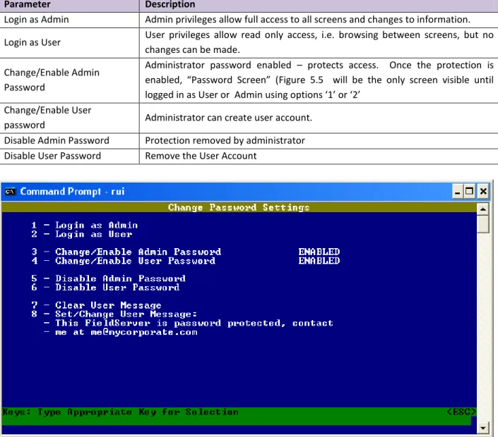
The P screen allows the administrator to restrict access to data and the ability to make changes. Password protection is disabled by default.
Figure 5.4
1
Cache blocks are temporary Map Descriptors created by the FieldServer to achieve certain objectives such as a write through or port expansion. Because they are temporary this number rise and fall is not visible. The read cache blocks persist until they expire after the Cache_Age_To_Live time has expired.
FieldServer Technologies 1991 Tarob Court Milpitas, California 95035 USA Web: www.fieldserver.com Login as Admin Admin privileges allow full access to all screens and changes to information. Login as User User privileges allow read only access, i.e. browsing between screens, but no
changes can be made. Change/Enable Admin
Password
Administrator password enabled – protects access. Once the protection is enabled, “Password Screen” (Figure 5.5 will be the only screen visible until logged in as User or Admin using options ‘1’ or ‘2’
Change/Enable User
password Administrator can create user account. Disable Admin Password Protection removed by administrator Disable User Password Remove the User Account
Figure 5.5 – Password Enabled Screen
5.4
O - Connection Overview
This screen supplies information on communication between the FieldServer and remote devices. A number of aspect screens are available, and some of the aspect screens have more than one page. Use the space bar to toggle between aspects and the PgUp, PgDn keys to toggle between pages of the same aspect. The Connection Overview and Settings Aspect screens are depicted below. The various parameters are described more fully in the tables that follow.
Every attempt is made to standardize the way in which drivers report stats but in some drivers unavoidable differences exist. In general, however, Rx Msg and Tx Msg correspond closely when connection is healthy. Connection number. - Type number
to go to detail for that connection, e.g. type 01 to navigate to detail for connection port N1
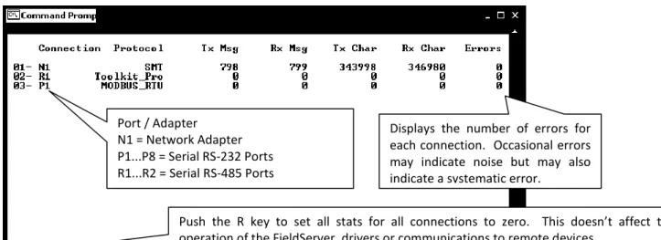
Figure 5.6 – Connection Overview Screen
Figure 5.7 – Connection Overview – Settings aspect – Page 1
5.4.1
Connection Overview – Settings Aspect.
Parameter Description
Connection The current connection out of the total number of connections. Adapter An adapter ID is displayed if the driver is an adapter driver. Poll_Delay
The minimum amount of time that must pass between one Client Map
Descriptor completing its task and the next Client Map Descriptor being serviced. Refer to Driver Manuals.
Low_Pri_Poll_Delay The poll delay used for lower priority Map Descriptors.
Server_Hold_Timeout
When an upstream device polls the FieldServer, and the data is unavailable or too old, the driver generates a poll to the downstream device for fresh data, (port expansion). The Server_Hold_Timeout defines the time available for this transaction to complete before an error is returned. The default is 2 seconds. Protocol The name of the protocol used by this connection.
IP_Address An IP address for the connection if applicable. Port / Adapter
N1 = Network Adapter P1...P8 = Serial RS-232 Ports R1...R2 = Serial RS-485 Ports
Push the R key to set all stats for all connections to zero. This doesn’t affect the operation of the FieldServer, drivers or communications to remote devices.
Displays the number of errors for each connection. Occasional errors may indicate noise but may also indicate a systematic error.
To view next connection, use the arrow keys.
This is the aspect named “Settings”. An aspect is a collection of related information.
See a filtered list of nodes which displays only those nodes which are using the connection currently displayed on the screen.
FieldServer Technologies 1991 Tarob Court Milpitas, California 95035 USA Web: www.fieldserver.com Remote_IP_Address A remote IP address for the connection if applicable.
Port Identifies the port for a serial driver. P1... P8 or R1...R2
Timeout* The timeout defined for the connection. Default 2 seconds. See Appendix C.1 for further information.
Recovery_Interval The time after a node goes off-line before the driver tries to poll the device again. Default 30 seconds.
Probation_Delay The length of time communication needs to be re-established for before an offline Client node is marked on-line again. Default 1 minute.
Connection_Mode Server (passive) or client (active).
Client/Server_Mode Optional setting to force a connection mode. Possible values are Server, PLC, Hot_Standby, Hot_Standby_Data, Client_Only, Diagnostic.
Multidrop_Mode Indicates whether Multidrop mode is enabled or not. Refer to Appendix C.1.3 for more information.
Turnaround_Delay The delay that the driver imposes between receiving a poll and sending a response. The default is 5ms for serial drivers.
Baud
Connection baud rate used by serial drivers. Some drivers override this value because the communication protocol allows the baud rate to be changed by the master.
Data_bits The number of data bits used for serial communication by the connection. The values are 7 or 8.
Parity The parity mode used by the connection to detect communication errors. Values are even, odd or none. The default is none.
Stop_Bits The number of stop bits used for serial communication by the connection. The values are 1 or 2.
Line_drive_on Time a serial driver using RS-485 will wait before driving the communications line after receiving permission. Default is 1milisecond.
Line_drive_off Time that a communication line using RS-485 is actively driven before being released, after the last bit has been sent. Default 1milisecond..
IC_timeout
Time a driver will wait between receiving the first and second bytes of a message before generating an IC Timeout. Default 0.5 seconds. See Appendix C.1.4 for more information.
IP_port
Determined by specific driver or protocol used. See Driver Manual. Remote_IP_Port
Max_Master Max_Info_Frames Connection_Type Application
5.4.2
Connection Overview - Status Aspect
Parameter DescriptionConnection The current connection being displayed out of the total number. Timer
The use of this variable to determine timeouts is driver dependent and has no consistent meaning. In passive drivers this variable may not have been used at all. In simple poll response drivers this variable should decrease from its maximum (equal timeout value) to zero.
5.4.3
Connection Overview - Statistics Aspect
Connection statistics are a roll-up of all the statistics maintained by the Nodes and Map Descriptors using the connection. For example: If three Map Descriptors use a single connection then each time a message is sent for each Map Descriptor, the Map Descriptor, Node and connection statistics are all updated. Thus response time statistics are more meaningful when viewing individual nodes and Map Descriptors.
Parameter Description
Connection The current connection being displayed out of the total number
Client Read Msg sent The number of read messages sent by a driver acting as a Client. May include messages sent to connect to the Server.
Client Read Msg recd The number of responses received to read messages sent by a driver acting as a Client. For most drivers this statistic quals the number of messages sent. Client Write Msg sent The number of write messages sent by a driver acting as a Client. May include
messages sent to connect to the Server.
Client Write Msg recd The number of responses received to write messages sent by a driver acting as a Client. For most drivers this statistic equals the number of messages sent. Client Passthru messages
This statistic relates to port expansion. Messages that are unrecognized (unsupported) are passed through the FieldServer without the contents being considered.
Client Passthru Msg sent The number of unrecognized messages passed through the FieldServer.
Client Passthru Msg recd The number responses to unrecognized messages passed through the FieldServer. Client Broadcast msg The number of broadcast messages sent.
Client Bytes Sent Number of bytes contained in messages sent by the driver acting as a Client. May include bytes of messages used to connect or login to the remote device.
Client Bytes Recd
Number of bytes contained in messages received by the driver when acting as a Client - typically responses to messages sent. May include bytes of messages used to connect or login to the remote device.
Server Msg recd
The number of messages received by a driver acting as a Server. May include non-data messages such as connection or login requests and port supervision
messages.
Server Msg sent The number of messages sent by a driver acting as a server - typically responses to messages received. May include responses to non-data messages as above. Server Bytes Sent A count of the bytes sent by the driver when acting as a Server in response polls.
May include bytes contained in non-data messages.
Server Bytes Recd A count of the bytes received by the driver when acting as a server. May include bytes contained in non-data messages.
Cache - Hits The number of times a cache Map Descriptor containing current data has been polled. See Appendix C.1.5
Cache - Misses The number of times a cache Map Descriptor containing outdated data has been polled. See Appendix C.1.5
Cache - Created
The number of times a cache Map Descriptor containing outdated data has been polled resulting in the creation of a new cache Map Descriptor. See Appendix C.1.5
Cache - Bumped The number of expired cache blocks. See Appendix C.1.5 Pex Write Thru
Writes are never cached - the external device is put on hold while the FieldServer resends the message to the PLC and waits for the response. When the FieldServer receives the response from the PLC it in turn responds to the external device. This
FieldServer Technologies 1991 Tarob Court Milpitas, California 95035 USA Web: www.fieldserver.com operation is counted as a PEX Write thru.
Server Response Max
The maximum time that the FieldServer has taken since the last reset to receive a message from an external device, poll the PLC and respond to the external device. The SCADA Hold Timeout parameter should be set higher than this limit
Server Response Avg
This is the average time that the FieldServer has taken since the last reset to receive a message from an external device, poll the PLC and respond to the external device. Reconfigure if response times are slow.
Link Control
This parameter is applied differently in different drivers. Please refer to the appropriate Driver Manuals. The Drivers that currently make use of this paramater are: AB-TCP, GE-SRTP, EST3, Modbus Plus.
Who-Is-Router-To-Network
BACnet specific – see Driver Manual. I-Am-Router-To-Network
Reject-Msg-To-Network
Messages Reconstructed Metasys®2 Specific – see Driver Manual.
Unsupported Property The driver encountered an unsupported property in a message. Unsolicited Messages Recd A message was received without the driver polling for it. Single Write A write data message containing a single data element. Single Item Read A read data message requesting a single data element. Block Write A write message containing a block of data elements. Block Read A read message requesting a block of data elements.
Sequence Error Messages containing sequence numbers received out of sequence. Data Object Startup Data requested from a node in start-up mode.
Expedite Read The number of Map Descriptors given the highest priority to complete a read/write first.
Expedite Write
Fasttrack Read The number of Map Descriptors given a higher priority to complete a read/write as soon as possible.
Fasttrack Write
Fasttrack Overrun Read The number of times the buffer holding fasttrack read/write Map Descriptors overflowed.
Fasttrack Overrun Write Max Read Response Time
Maximum/Minimum/Average time in seconds that passed before a response was received to a read message sent by a driver acting as a Client.
Min Read Response Time Avg Read Response Time Max Write Response Time
Maximum/Minimum/Average time in seconds that passed before a response was received to a write message sent by a driver acting as a client.
Min Write Response Time Avg Write Response Time Max Passthru Response Time
Maximum/Minimum/Average time in seconds to receive a response to a poll sent using the Passthru mechanism.
Min Passthru Response Time
Avg Passthru Response Time
TCP Conn Lost Number of times a TCP connection was lost or interrupted. TCP Send Failed Number of times a message sent on TCP connections failed.
5.4.4
Connection Overview - Error Statistics Aspect
Parameter Description
Connection The current connection being displayed out of the total number. PEX No slave
PEX No Slave is intended for a multidrop context where it shows that messages are being ignored because the corresponding slave is not configured on our device. See Driver Manual for further information.
Server Overruns A message arrived from the upstream device while the server port was on hold. Increase the timeout setting in the external device.
Server Hold Timeouts
If an upstream device requests data from a cache where the data is too old then the data will be refreshed by polling from the downstream device. The response was not received in time.
Timeouts
A remote device never responded to the FieldServer poll. Either the device is not responding, or one of the timeout parameters is set too low. Ensure that the device is online and addressed correctly and if necessary increase the relevant timeout parameter in the CSV file.
Checksum Errors
External influences e.g. electrical noise corrupted the data. Check that communication cables are shielded, not too long and do not run past power cables.
Protocol Errors An external device responded with unexpected or unknown messages. Consult the relevant driver manual.
Noise Corrupted or garbage bytes on a communications line. Bad Length A message that looks Ok, but is of the incorrect length.
Bad Node A no-response/error response from an addressable external device. Bad Function E.g. an external device is written to that does not support writes. No Start Communications to an external device could not be started. PLC exception A variation of a NAK message produced by some protocols. NAK A NAK message is received in response to a poll.
Streaming
Data seems to be continuously arriving from an external device. This could be due to a mismatch in baud rates.
Streaming errors are typically produced when:
1) The transmitter sends more data than the FieldServer can process. 2) An unexpectedly long message is received or messages have been
corrupted so that the end of a previous message cannot be detected. 3) A message longer than the driver expects has been received.
Premature
A response from an external device arrived before it was expected, implying that it is not the response for the poll the FieldServer has just sent. This could occur when there are time delays in communication networks which contain bridges and routers which may delay messages for longer than expected. Increase the timeout parameter for the connection to eliminate these errors.
Preamble Characters preceding a message were dropped.
IC Timeouts Too much time between receiving successive bytes in a message.
Address Errors A driver tried to address a wrong device or a wrong block of data within an external device.
Data Object offline A poll was received for a node that is offline.
Node Offline An external device node is offline in response to a driver or external device trying to access it.
FieldServer Technologies 1991 Tarob Court Milpitas, California 95035 USA Web: www.fieldserver.com Msg Ignored Messages received but unable to be processed - normally because the driver has
not implemented functionality for that message.
Sys Cleared The number of times that Data Arrays were cleared after a system-normal type message was received from a device (e.g. fire alarm panel)
Squelch TX3 The number of bytes received during the squelch timing period started when RTS is asserted.
Squelch RX1 The number of bytes received during the squelch timing period started when RTS is de-asserted.
Cache Failed FieldServer unable to create a cache block due to memory shortage or inability to find a downstream node.
Segmentation Not Supported
The received message was segmented but the driver does not support re-assembling segmented messages.
Passthru Retries4 Produced when a Passthru poll is busy on the downstream side, and an identical poll (retry) is received on the upstream side.
Passthru Overruns2 Produced when a Passthru poll is busy on the downstream side and a different poll (not a retry) is received on the upstream side.
Passthru Early Retries A Passthru Retry, which occurs when the upstream retry is received before the 1 st
downstream Passthru poll has been sent.
Passthru Normal Retries A Passthru Retry, which occurs when the upstream retry is received after the 1 st
downstream Passthru poll has been sent.
Passthru Early Overruns A Passthru Overrun, which occurs when the upstream retry is received before the 1st downstream Passthru poll has been sent.
Passthru Normal Overruns A Passthru Overrun, which occurs when the upstream retry is received after the 1 st
downstream Passthru poll has been sent. Passthru Early Overruns
Fails
This statistic is currently not used. Passthru Normal Overruns
Fails
PWT Expired The Passthru Window Timer expired before the downstream Passthru poll could be sent.
5.4.5
Connection Overview - API Aspect
These statistics are produced by the FieldServer kernel’s API (Application Programmer Interfaces). They are intended for advanced users only.
Press the 1 key or the 2 key to change the filter on these stats. 1 = TCP API
2 = Ethernet API (Default)
Parameter Description
Connection The current connection being displayed out of the total number TX bytes Number of bytes sent.
3
Information is available in ENOTE19. Enotes are available on the flash drive shipped with the FieldServer.
4
Parameter Description
TX packets Number of packets sent.
TX dropped Number of packets not sent for reasons that include the transmit buffers being full. TX errors Errors during transmission such as hardware errors.
RX IP fragments The number of IP fragmented packets received. Collisions Number of collisions - the network is too busy. TX abort errors
The NIC layer reports this error. Should be zero. TX carrier errors
TX heartbeat errors TX window errors Max TX buffers used
The highest value for the used transmit buffer count since the FieldServer was restarted. An extremely busy network may have a max of 7 or 8 but values this high are unusual.
Tx buffers in use Current transmit buffers in use.
Tx broadcast The number of broadcast messages sent. RX bytes Number of bytes received by the API. RX pkts total Number of packets received by the API.
RX pkts for us The number of received packets destined for transmission.
RX pkts NOT for us The number of received packets destined for transmission not meant for the API. RX dropped The number of received packets which were dropped for reasons such as the Ethernet
queue being full. RX errors
The NIC layer reports this error. Should be zero. RX length errors RX overflow errors RX crc errors RX frame errors RX frame errors RX buffer full RX ring buffer error
RX IP type Number of messages using IP protocol received. RX ARP type Number of messages using ARP protocol received. RX BACNET type Number of messages using BACnet protocol received. RX 802_3 type Number of messages using 802_3 Ethernet protocol received. RX UNKNOWN type Number of messages using other Ethernet protocol received. Frag buf overrun IP defrag on the receive side. The buffer is (about 80kb) is full. RX Broadcast Number of packets received in broadcast.
Exception 1 The Ethernet packet type could not be identified Exception 2
An Ethernet packet received (i.e. addressed to the FieldServer Ethernet address) was addressed to another IP address - either an Ethernet broadcast was sent with a specific IP address, or another device has an incorrect ARP table.
Exception 3 A UDP packet of length >1500 was received which cannot be handled by the FieldServer.
Exception 4 The Ethernet TX interrupt handler was kick started. RX global timeout
This statisticis currently not used. RX local timeout
RX IP not for us The number of received IP packets not meant for the FieldServer. Max RX buffers used The maximum number of receive buffers used since restart.
FieldServer Technologies 1991 Tarob Court Milpitas, California 95035 USA Web: www.fieldserver.com Rx buffers in use The number of receive buffers currently in use.
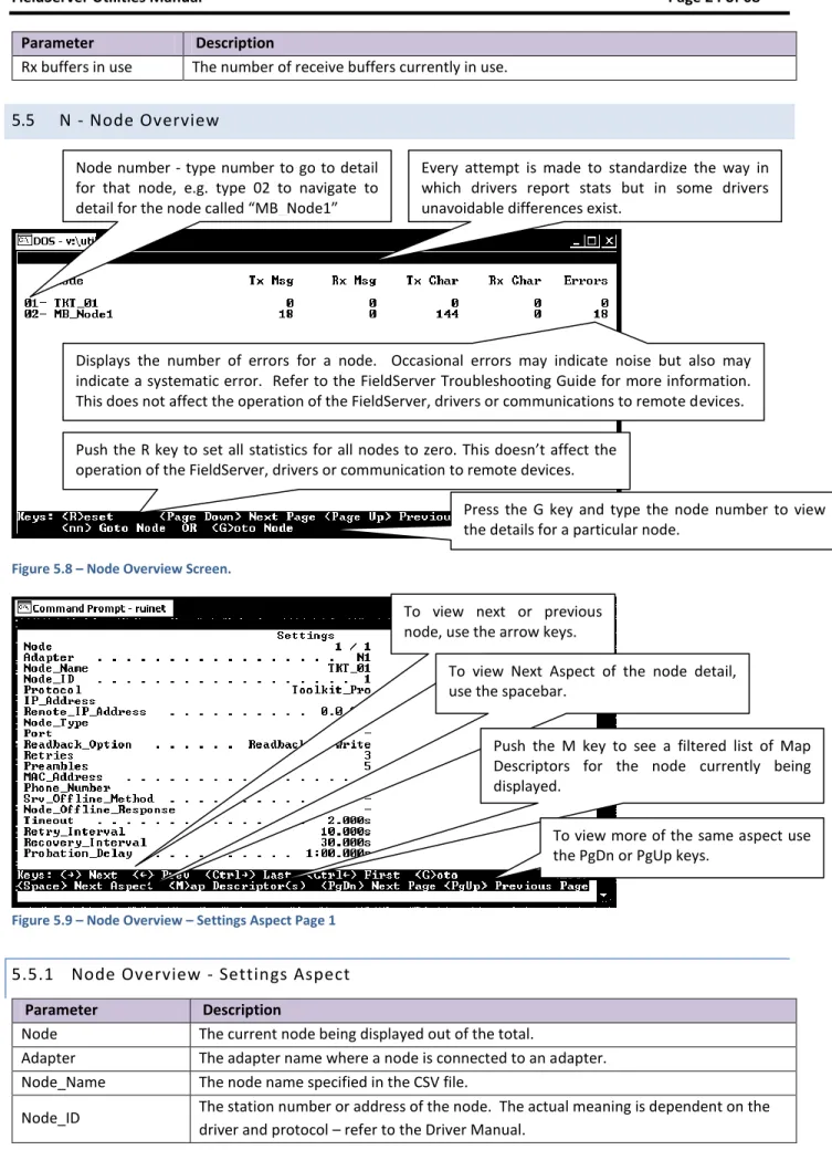
5.5
N - Node Overview
Figure 5.8 – Node Overview Screen.
Figure 5.9 – Node Overview – Settings Aspect Page 1
5.5.1
Node Overview - Settings Aspect
Parameter Description
Node The current node being displayed out of the total.
Adapter The adapter name where a node is connected to an adapter. Node_Name The node name specified in the CSV file.
Node_ID The station number or address of the node. The actual meaning is dependent on the driver and protocol – refer to the Driver Manual.
Press the G key and type the node number to view the details for a particular node.
Displays the number of errors for a node. Occasional errors may indicate noise but also may indicate a systematic error. Refer to the FieldServer Troubleshooting Guide for more information. This does not affect the operation of the FieldServer, drivers or communications to remote devices. .
Every attempt is made to standardize the way in which drivers report stats but in some drivers unavoidable differences exist.
Node number - type number to go to detail for that node, e.g. type 02 to navigate to detail for the node called “MB_Node1”
Push the R key to set all statistics for all nodes to zero. This doesn’t affect the operation of the FieldServer, drivers or communication to remote devices.
To view next or previous node, use the arrow keys.
To view Next Aspect of the node detail, use the spacebar.
Push the M key to see a filtered list of Map Descriptors for the node currently being displayed.
To view more of the same aspect use the PgDn or PgUp keys.
Parameter Description
Protocol The protocol being used to update the data for that node. Refer to the Driver Manual IP_Address The IP address used by this node.
Remote_IP_Address The remote IP address used by this node
Node_Type Specified in the configuration file as the PLC_Type. - Consult the driver manual for additional information.
Port Port number for a serial connection.
Readback_Option
After a write has been executed in a write through operation, the FieldServer
schedules the read Map Descriptor to poll again in order to immediately read back the data that was written. The default is ‘Readback_on_Write”. Other options are “None” and “Expire_Current_Data”
Retries Tells the driver how many times to retry a poll before considering the node to be offline. The default is 3.
Preambles Counts data bytes received before a valid message, but not forming part of a valid message, e.g. a message fragment.
MAC_Address Currently this field is not used. It is intended to allow drivers to resolve an IP address by giving a MAC address.
Phone_Number This field is intended for modem support. Currently disabled.
Srv_Offline_Method The method used on the node to decide if it is to be considered offline.
Node_Offline_response The type of response the Server side of the driver sends when it finds the Server node to be offline.
Timeout The timeout specified for the node. Refer to Appendix C.1.
Retry_Interval The amount of time in seconds that the driver should wait before retrying a poll after a timeout has occurred
Recovery_Interval The time in seconds after a node goes off-line before the driver tries to poll the device again. – default 30seconds.
Probation_Delay The length of time communication needs to be re-established for before an offline Client node is marked on-line again. Default 1 minute.
Network_Number Network station number used on this node.
Server_Name
An alternate to specifying the IP address. Typically used when the user wants two nodes to talk to each other. When specified, the FieldServer sends out a broadcast with the server name and uses the reply to fill in the IP address for the node. Until the reply has been received all polling for the node is disabled. The server name given should correspond to the pair_name specified in the remote FieldServer’s bridge settings.
Alias_Node_ID
This is used to distinguish between different nodes connected to the FieldServer when a PLC does not support the allocation of different None_ID’s. Each node is given a different alias. Upstream devices poll the Alias_Node_ID and the FieldServer routes the poll to the correct PLC which is polled using the Node_ID.
Ports_on_PLC For hot standby operation. This field is used to control which port on a PLC to poll.
5.5.2
Node Overview - Status Aspect
Parameter DescriptionNode The current node being displayed. Node Status
For a Client node. Online, offline, disabled or probation. Probation means that the node is in transition from offline to online. The node was offline, a poll has succeeded but the probation timeout has not expired so the node has not been returned to online yet. If the node isn’t a
FieldServer Technologies 1991 Tarob Court Milpitas, California 95035 USA Web: www.fieldserver.com client node then it is reported as server.
Node Mode Client or Server
Retry State The state number of the node retry state engine – for FieldServer developers. Used Retries The total number of retries since start-up
Recoveries The number of times that the driver has gone from offline to online.
Active R/W on Startup
This is an important indication if the driver appears not to be polling. Displays yes or no. If a Map Descriptor with function = “ARS” (Active Read on Startup) is found then this field reports as ‘yes’. ARS Map Descriptors are scheduled to occur when a node is still offline and are only used once. They are intended to establish a connection or to log into a remote device. No other Map Descriptors are polled until the ARS Map Descriptors complete normally.
5.5.3
Node Overview - Operating Statistics Aspect
Node statistics are a roll-up of all the statistics maintained by the Map Descriptors which belong to the node. For example, if three Map Descriptors belong to a single node, then each time a message is sent for each Map Descriptor, the statistics for the Map Descriptor, the node and the connection are updated.
Parameter Description
Node The current node being displayed. Client Read Msg sent
Refer to Section 5.4.1 for a description. On this screen the statistic count applies to the node only.
Client Read Msg recd Client Write Msg sent Client Write Msg recd Client Passthru Msg sent Client Passthru Msg recd Client Broadcast msg Client Bytes Sent Client Bytes Recd Server Msg recd Server Msg sent Server Bytes Sent Server Bytes Recd Cache - Hits Cache - Misses Cache - Created Cache - Bumped PEX Write thru Server Response Max Server Response Avg Link Control
Messages Reconstructed Unsupported Property Unsolicited Messages Recd Single Write
Single Item Read Block Write Block Read
Parameter Description Sequence Error
Data Object Startup Expedite Read Expedite Write Fasttrack Read Fasttrack Write Fasttrack Overrun Read Fasttrack Overrun Write Max Read Response Time Min Read Response Time Avg Read Response Time Max Write Response Time Min Write Response Time Avg Write Response Time Max Passthru Response Time Min Passthru Response Time Avg Passthru Response Time TCP Conn Lost
TCP Send Failed
5.5.4
Node Overview - Error Statistics Aspect
Parameter Description
Node The current node being displayed. PEX No slave
Refer to Section 5.4.3 for a description. On this screen the count applies to the node only.
Server Overruns Server Hold Timeouts Timeouts Checksum Errors Protocol Errors Noise Bad Length Bad Node Bad Function No Start PLC exception NAK Streaming Premature Preamble IC Timeouts Address Errors Data Object offline Node Offline Msg Ignored Sys Cleared
FieldServer Technologies 1991 Tarob Court Milpitas, California 95035 USA Web: www.fieldserver.com Squelch TX
Squelch RX
Segmentation Not Supported Passthru Retries
Passthru Overruns Passthru Early Retries Passthru Normal Retries Passthru Early Overruns Passthru Normal Overruns Passthru Early Overrun Fails Passthru Normal Overrun Fails PWT Expired
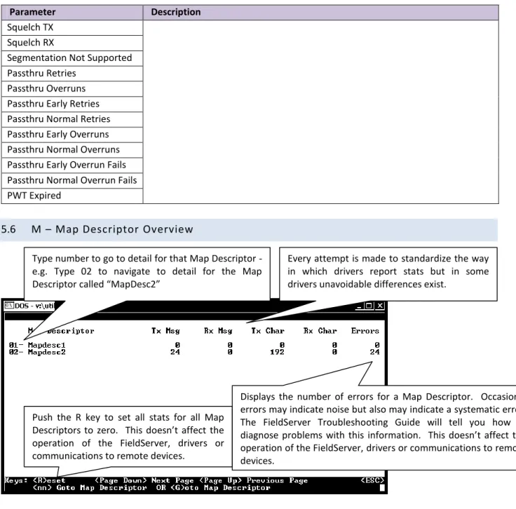
5.6
M – Map Descriptor Overview
Figure 5.10 – Map Descriptor Overview Screen
Every attempt is made to standardize the way in which drivers report stats but in some drivers unavoidable differences exist.
Type number to go to detail for that Map Descriptor - e.g. Type 02 to navigate to detail for the Map Descriptor called “MapDesc2”
Push the R key to set all stats for all Map Descriptors to zero. This doesn’t affect the operation of the FieldServer, drivers or communications to remote devices.
Displays the number of errors for a Map Descriptor. Occasional errors may indicate noise but also may indicate a systematic error. The FieldServer Troubleshooting Guide will tell you how to diagnose problems with this information. This doesn’t affect the operation of the FieldServer, drivers or communications to remote devices.
Figure 5.11 – Map Descriptor Overview – Settings Aspect
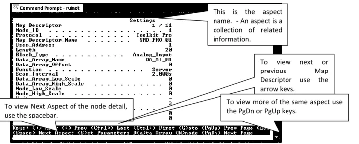
5.6.1
Map Descriptor Overview - Settings Aspect
Parameter Description
Map Descriptor The current Map Descriptor being displayed out of the total
Node_ID The Node ID used by this Map Descriptor when the driver builds read or write messages..
Protocol The protocol used by this Map Descriptor. Map_Descriptor_Name Used to identify a Map Descriptor by name.
User_Address Allows a Map Descriptor to address remote device data at a specific start memory location.
Length Alows a Map Descriptor address a number of remote device data locations from the start address.
Block_Type
Used by some drivers to indicate the data format used to pack a block of data, e.g. when reading a block of 4 bytes from a PLC and the Block_Type is Word, the incoming data will be interpreted as 2 words.
Data_Array_Name The name of the Data Array where information will be stored to and retrieved from by the Map Descriptor.
Data_Array_Offset The offset into the Data Array where data should be stored on reads or retrieved from on writes.
Function The Map Descriptor function can be mainly read or write with a number of variations of each. Refer to the FieldServer Configuration Manual for other functions.
Scan_Interval When using continuous Map Descriptor functions such as RDBC, this is the time a Map Descriptor will wait before polling for data again.
Data_Array_Low_Scale
Used in the scaling of data values before storing them or before sending them in write messages. Consult the Driver manual to determine whether the driver supports scaling.
Data_Array_High_Scale Node_Low_Scale Node_High_Scale
Units Used to specify engineering units to interpret data if used. Will display a dash if not used.
Network Used by some drivers as a network number.
Sector Used by some drivers as a sector number for rack addressing. To view Next Aspect of the node detail,
use the spacebar.
To view next or previous Map Descriptor use the arrow keys.
To view more of the same aspect use the PgDn or PgUp keys.
This is the aspect name. - An aspect is a collection of related information.
FieldServer Technologies 1991 Tarob Court Milpitas, California 95035 USA Web: www.fieldserver.com Card Used by some drivers as a card number for rack addressing.
5.6.2
Map Descriptor Overview – Status Aspect
Parameter DescriptionMap Descriptor The current Map Descriptor being displayed out of the total.
Scan Timer Value of scan timer used by driver for this Map Descriptor. This is for debugging purposes only and has no specific meaning.
5.6.3
Map Descriptor Overview - Operating Statistics Aspect
Parameter Description
Map Descriptor The current Map Descriptor being displayed out of the total. Client Read Msg sent
Refer to Section 5.4.1 for a description. On this screen the statistic count applies to the Map Descriptor only.
Client Read Msg recd Client Write Msg sent Client Write Msg recd Client Passthru Msg sent Client Passthru Msg recd Client Broadcast msg Client Bytes Sent Client Bytes Recd Server Msg recd Server Msg sent Server Bytes Sent Server Bytes Recd Cache - Hits Cache - Misses Cache - Created Cache - Bumped PEX Write thru Server Response Max Server Response Avg Link Control
Messages Reconstructed Unsupported Property Unsolicited Messages Recd Single Write
Single Item Read Block Write Block Read Sequence Error Data Object Startup Expedite Read Expedite Write Fasttrack Read Fasttrack Write
Parameter Description Fasttrack Overrun Read
Fasttrack Overrun Write Max Read Response Time Min Read Response Time Avg Read Response Time Max Write Response Time Min Write Response Time Avg Write Response Time Max Passthru Response Time Min Passthru Response Time Avg Passthru Response Time TCP Conn lost
TCP Send Failed
5.6.4
Map Descriptor Overview - Error Statistics Aspect
Parameter Description
Map Descriptor The current Map Descriptor being displayed out of the total number of Map Descriptors.
PEX No slave
Refer to Section 5.4.3 for a description. On this screen the statistic count applies to the Map Descriptor only.
Server Overruns Server Hold Timeouts Timeouts Checksum Errors Protocol Errors Noise Bad Length Bad Node Bad Function No Start PLC exception NAK Streaming Premature Preamble IC Timeouts Address Errors Data Object offline Node Offline Msg Ignored Sys Cleared Squelch TX Squelch RX
Segmentation Not Supported Passthru Retries
FieldServer Technologies 1991 Tarob Court Milpitas, California 95035 USA Web: www.fieldserver.com Passthru Early Retries
Passthru Normal Retries Passthru Early Overruns Passthru Normal Overruns Passthru Early Overruns Fails Passthru Normal Overruns Fails PWT Expired
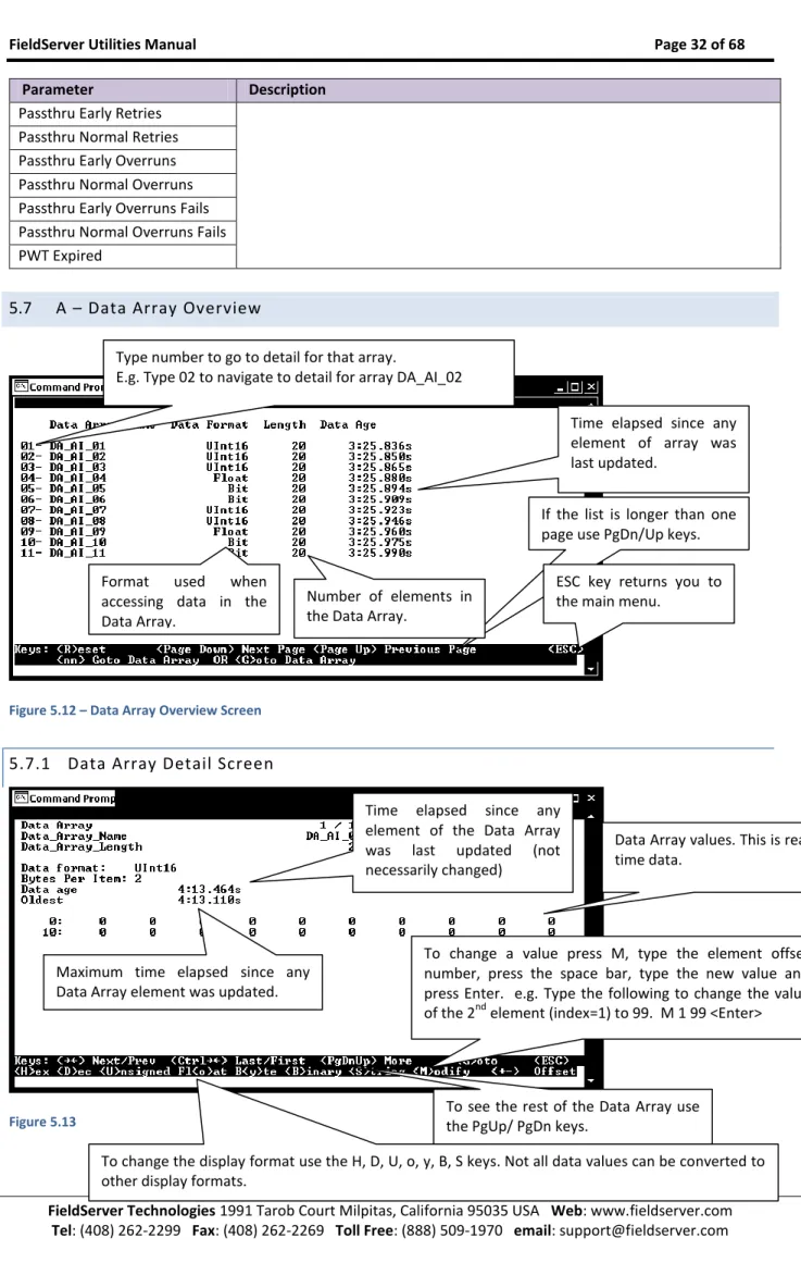
5.7
A – Data Array Overview
Figure 5.12 – Data Array Overview Screen
5.7.1
Data Array Detail Screen
Figure 5.13
Type number to go to detail for that array.
E.g. Type 02 to navigate to detail for array DA_AI_02
Time elapsed since any element of array was last updated.
Format used when accessing data in the Data Array.
If the list is longer than one page use PgDn/Up keys.
ESC key returns you to the main menu.
Time elapsed since any element of the Data Array was last updated (not necessarily changed)
Maximum time elapsed since any Data Array element was updated.
Data Array values. This is real time data.
To change a value press M, type the element offset number, press the space bar, type the new value and press Enter. e.g. Type the following to change the value of the 2nd element (index=1) to 99. M 1 99 <Enter>
To see the rest of the Data Array use the PgUp/ PgDn keys.
To change the display format use the H, D, U, o, y, B, S keys. Not all data values can be converted to other display formats.
Number of elements in the Data Array.
5.8
L – Message Log
This screen shows normal informational type messages from the operating system Error! Objects cannot be created from editing field codes.
Figure 5.14
5.9
E – Error Messages
The error screen will show error messages printed by the FieldServer kernel which should normally have a SDO meaning. Driver messages for older drivers (pre 2003) also send their messages to the E screen. The error screen is a circular buffer which can hold a limited number of lines of information. Once full, as each new line is added to the bottom of the buffer, the top line is removed.
Error! Objects cannot be created from editing field codes. Figure 5.15
Figure 5.16
5.10
F – Driver Messages
Informational type messages from protocol drivers, eg. Modbus or BACnet are printed on this screen. Error! Objects cannot be created from editing field codes.
Figure 5.17
5.11
C – Combined Log
All messages from the E, F and L screens are displayed on this screen
Error! Objects cannot be created from editing field codes.
To clear the error screen push the R key. This doesn’t affect the operation of the FieldServer, drivers or communications to remote devices.
Press V to Display version information.
Other messages – non critical but may assist in troubleshooting.
Driver Messages(older drivers) – informational only, but may assist in troubleshooting.
To see more push the PgDn or PgUp keys
System Errors cause the FieldServer to turn on the red SYS LED on the FieldServer front panel.
Please report all system errors to FieldServer Technologies.
Turn the LED off by clearing the E-screen with the R key.
Kernel Messages - informational messages for FieldServer use, normally non critical.
FieldServer Technologies 1991 Tarob Court Milpitas, California 95035 USA Web: www.fieldserver.com
5.12
D – Download Configuration to FieldServer
Figure 5.19
Figure 5.20
5.12.1
Procedure for Downloading a File from a PC t o a FieldServer
From the main menu select “D” to go to the download screen. Specify the local file name by selecting “L”, type the file name and press <Enter> If the remote filename is incorrect, select “R”, type the file name and press <Enter>.
Begin the download by selecting “D”.
Press D to enter the file download screen. Download means to transfer a file from your PC to the FieldServer.
Update firmware.
Push the F key and the file fserver.img will be downloaded from the
config folder. Use the O key to enable the downloading of ‘other’ files. When enabled you can download files other than .csv to the FieldServer. Please exercise caution with this option.
Path names are allowed when you type in the local file name. Path names are not allowed when you type in the remote file name.
5.13
U - Upload Configuration from FieldServer
Figure 5.21
Figure 5.22
5.13.1
Procedure to Upload a File from a FieldServer to a PC
From the main menu, select “U” to go to the Upload screen. Select “R”, type in the remote file name (File on the FieldServer) and press <Enter> If the local file name is incorrect, select “L”, type the name and press <Enter>.
Begin the upload by pressing “U”.
When the upload is completed, the uploaded file may be opened with one of the listed editors. Note that the editors are not supplied with RuiNet and must be loaded on your machine to work effectively.
See Appendix B.2.10 for more information
5.14
I - Change IP Address
From the main menu, press “I” to enter the Edit IP Address Settings menu.
Press U to enter the file upload screen.
Upload means to transfer a file from the FieldServer to a PC.
Use the O key to enable the uploading of ‘other’ files.
When enabled you can upload files other than .csv from the FieldServer. Please exercise caution with this option.