A Simple Classroom Network Access Control System
Hangjin Zhang, Kevin C. AlmerothDepartment of Computer Science University of California Santa Barbara, CA 93106-5110 {hangjin, almeroth}@cs.ucsb.edu
Abstract: With the advent of laptop computers and network technology, many classrooms are now being equipped with Internet connections, either through wired connections or wireless infrastructure. Internet access provides students an additional source from which to obtain course-related information. However, constant access to the Internet can be a distraction. This distraction could potentially cause impaired learning performance. Instructors need a mechanism to control how students access the Internet; and researchers need a mechanism to monitor students’ computer activities and engagement. To fulfill these two needs, we propose a simple Classroom Network Access Control (CNAC) system. Our system consists of two major parts: the Ethernet bridge as a core and the web-basedcontrol panel as the user interface. The CNAC system is designed to be easily deployed and the simple and intuitive web-based control panel provides a user-friendly configuration interface for instructors. Through this powerful, yet flexible interface, instructors can easily set classroom Internet access rules.
Introduction
With the advent of laptop computers and network technology, many universities have deployed wired or wireless network infrastructure in classrooms and computer labs. In these classrooms, smart whiteboards, Personal Digital Assistants (PDAs), and computers are being used in lecture presentations (Anderson et al. 2004), for note taking (Singh et al. 2004), or for stimulating interaction and collaboration (Anderson et al. 2003). Technology is also being used for a wide variety of other creative uses (Campbell & Pargas 2003; Moody & Schmid 2004; Ryder 2000). These classroom activities require each student to use an Internet- (or at least, intranet-) connected computer. On the one hand, in-class networks and computers help students gain course-relevant information more effectively from more sources. On the other hand, however, ubiquitous computer and Internet access may also have unintended side effects. For example, off-topic Internet surfing can be a distraction during a lecture. Reports also show that some instructors are not motivated to integrate computer technology into their courses, for fear of losing control in the classroom (Efaw et al. 2004; McWilliams 2005). These instructors are not comfortable having students frequently using their computers, because some students might be engaged in uses other than those related to the course. These instructors would only feel comfortable if they had a mechanism that could control, or at least limit, student’s in-class computer activities.
In addition to the control requirement, researchers studying classroom engagement often need a mechanism to
monitor student’s classroom activities for further behavior analysis.Introducing laptops and Internet access into the classroom clearly changes the learning psychology (Fisher & Stolarchuk 1998). Education and psychology researchers are interested in assessing the impact of technology in classrooms. For this purpose, the first important step is to collect information about what students do on their computers. In other words, researchers need a mechanism to monitor students’ activities in the classroom.
To satisfy these two requirements, one method is to install a software agent in every student’s computer to control and monitor activity (Zhang, Almeroth & Bulger 2005). The agent continuously monitors a student’s computer activities; records application open/close events and key strokes; and then reports the data to a central repository for later analysis. The software agent can also enforce resource access control based on predefined policies or rules. For example, the agent can block all web browsing traffic, or even prohibit a certain application from opening during a lecture. Although this dedicated software can perform many monitoring and control tasks, it is very difficulty, if not impossible, to make it work in all classroom settings. While such software could be deployed on all university-owned computers, there is no way to enforce that students install this software on their personal computers.
Since many university networks allow students to connect and use their own laptops, we are motivated to design a better alternative than the software agent method. In this paper, we propose a simple Classroom Network Access Control (CNAC) system. The goal of our CNAC system is to provide instructors with a tool to easily monitor and
control how students access the Internet during a lecture. Our system accomplishes its goal without the need to install any software on a student’s laptop, and without the need to change the existing campus network infrastructure. Our CNAC system has two major features: the centralized architecture and transparency. It is centralized because the core of the CNAC system resides at the edge of a classroom network, instead of being distributed on each student computer, and the rules for determining what students can access on the Internet are managed through a centralized web interface. CNAC works at the data link layer (e.g. Ethernet) of the International Standards Organization (ISO) Open System Interconnect (OSI) reference model and is transparent because neither the downstream computers nor upstream network devices are aware of the presence of the CNAC system.
Our CNAC system is designed as a core-shell structure. Figure 1 shows the three-level architecture of the proposed system. The inner core is the Ethernet bridge module and is implemented for the Linux 2.6 operating system. The middle layer is two user-space programs: ebtables and iptables, either of which passes commands to the inner core (Netfilter and Iptables 2005; Ebtables 2005). The outmost layer is a web-based control panel that acts as an interface between the user and the iptables and ebtables functions.
web-based control panel ebtables/iptables
Ethernet bridge
Figure 1. CNAC three-layer core-shell architecture.
The remainder of the paper is organized as follows. First we review related work. The next two sections then describe the two parts of our CNAC system: the Ethernet bridge and the web-based control panel. The remaining two sections describe our testbed experiments and then our conclusions and future work.
Related Work
Having seen frequent web surfing with wireless laptops during lectures, some universities have decided to eliminate connectivity in classrooms. The University of California at Los Angeles, the University of Virginia's Darden Graduate School of Business Administration, and the University of Houston have investigated the use of devices to block wireless access in classrooms. They have installed a switch in the room to let faculty easily turn wireless connectivity on and off (McWilliams 2005). This solution simply turns off wireless access, and is not flexible enough to provide fine-grained control. We think a more flexible solution is needed that allows instructors to take advantage of computer and network technology, while at the same time reducing or limiting any negative effects. Instead of blocking all wireless access, a network traffic filter or firewall should be used.
A firewall is a network security-oriented device. Many different kinds of firewalls exist and there are significant variations in their performance, functionality, and security levels. Most traditional firewalls work at the network layer and can make decisions about whether packets are forwarded or filtered based on network layer (e.g. IP) or transport layer (e.g. TCP or UDP) headers. As an important part of an organization’s network, the firewall is usually carefully configured and deployed at the beginning of the network construction phase by network security experts, and maintained by professional administrators. Challenges arise if a firewall is installed after the network has been built. Adding a firewall to a complex network can require a variety of network changes, for example, changes in the topology, address re-assignment, and re-configuration of network devices leading to the rest of the Internet.
A traditional firewall is not well-suited for classroom network access control because the goals of the firewall and classroom access control are different. First, the primary goal of a traditional firewall is to protect an internal network from external attacks. Second, once a firewall is deployed, the firewall rules are relatively static, i.e., unless new vulnerabilities are discovered, the rules are changed only infrequently. And third, a firewall usually applies the
same firewall rules to all internal computers, with only a few exceptions for critical servers. For a classroom network, the goal is to block certain types of network traffic from leaving the network based on instructor and lecture needs. Lecture needs can be quite dynamic, varying even for different courses at different times of the same day. If classroom network access control was performed using a traditional firewall, the firewall rules would need to be changed frequently, and the firewall would have to distinguish computers in different classrooms and possibly apply different rules. Due to the different requirements, traditional firewalls are not well-suited for this kind of use.
There is one commercial product aimed at classroom network access control: Enterasys’s Professional Real-work Online Facilitator (PROF) system (Enterasys 2005). It is a hardware-based solution that consists of two proprietary network devices: the Enterasys Matrix E7 switch and the X-Pedition router. Bently College has deployed a system based on Enterasys’s technology (Yancy 2001). The computer at the instructor podium is provided with a web interface to select one of the following connection options: (1) disable Internet access; (2) disable email; (3) disable Internet and email; and (4) disable all access. The access control task is then performed by the system hardware. This system costs $43,500 for the initial purchase plus an annual fee for a “maintenance contract.” PROF is the most similar system to our solution. Unlike PROF, however, CNAC uses open source software packages combined with a few simple helper scripts and standard network devices, as opposed to proprietary equipment and software. Therefore, the cost of our CNAC system is extremely low, virtually zero. In addition, besides the four fixed access types, our solution allows as many customized access rule sets as are desired. Instructors can simply select one of the pre-configured rule sets through the web interface, or an experienced instructor can develop his or her own customized rule set.
Another option beyond firewalls and custom hardware-based solutions, suitable only for small-scale Wireless LAN (WLAN) networks, is to use software available in some commercial Access Points (APs). Many APs have access control functions built-in. In a large campus-wide WLAN infrastructure, however, there are too many APs scattered throughout the network, and maintaining consistent access control policies for all APs is not easy. In order to manage a large number of APs, several protocols have been proposed and submitted to the Internet Engineering Task Force (IETF) for standardization. The Lightweight Access Point Protocol (LWAPP) (Calhoun et al. 2005), and the Control And Provisioning of Wireless Access Points (CAPWAP) protocol (Yang, Zefos & Sadot 2005) are two examples. In LWAPP or CAPWAP, the APs are only responsible for handling low-level Radio Frequency (RF) functions, and leave high-level control functions to one or more Access Controllers (ACs). The ACs provide centralized security and policy management. But since LWAPP- and CAPWAP-enabled APs are not yet widely available, they cannot be relied upon to provide effective classroom network access control.
Transparent Ethernet Bridge and Netfilter
As described in the previous section, a regular security-oriented firewall is not the best solution to perform the classroom network access control task. Our goal is to develop our CNAC solution by installing an additional dedicated device (e.g. a simple off-the-shelf personal computer) that (1) is able to control and monitor network traffic, (2) does not change the existing network topology, and (3) can be easily administrated and managed by non-technical staff. To achieve these goals, we propose a new approach: a transparent Ethernet bridge with a web-based control panel. The Ethernet bridge is utilized to control and monitor network access; the transparency guarantees no changes to the current network topology; and the web-based control panel provides an easy and user-friendly interface. In this section, we describe the core of the CNAC system, the Ethernet bridge.
Networking Background
Before we describe the details of the Ethernet bridge, we first briefly review some networking basics related to this technique. In the OSI network reference model, a network protocol stack is divided into seven layers. The three most important layers related to our solution are the data link, network, and transport layers. Different types of network devices provide functionality at different layers. For example, hubs, switches, and bridges work at the data link layer (also called Layer 2), and deal with Medium Access Control (MAC) addresses; while routers and normal IP-based firewalls work at the network and transport layers (also called Layers 3 and 4, respectively), and deal with IP address and TCP/UDP ports. When a packet leaves a source computer, it traverses the protocol stack from top to bottom, i.e. protocol headers for each layer are “stacked” on top of each other. When the packet arrives at the destination computer, it traverses the protocol stack from bottom to top and protocol headers are “unstacked”. As a packet is transferred across the network, intermediate routers process the lowest layers of the protocol stack, up to, and including, the network layer.
Ethernet is a widely used data link layer protocol for Local Area Networks (LANs). Computers on the LAN each have a Network Interface Card (NIC) with a unique MAC address. Ethernet “frames” are transmitted across the LAN, and based on the destination MAC address, are received by the correct computer. The normal behavior for Ethernet is for every frame to be received by every computer on the LAN. Therefore, a computer’s NIC is responsible for checking whether it is the destination for the frame. If the destination MAC address in the frame and the MAC address of the computer’s NIC match, the frame is passed to the network layer for further processing. Otherwise, if the two addresses do not match, the frame is discarded. There is a special operating mode, called “promiscuous mode”, that allows a NIC to receive all frames, regardless of the destination MAC address. This special mode is used by firewalls and access control software to monitor the network and possibly take action to prevent certain frames from being transmitted.
Linux Ethernet Bridge and Netfilter
A network bridge is a network device which connects two or more network segments transparently to form one subnet. An Ethernet bridge is a bridge between two network segments each running the Ethernet protocol. The Linux operating system includes a module to provide this bridging functionality. A computer with multiple Ethernet connections—accomplished using multiple NICs—can act as a bridge. All or some of the NICs in a computer can be associated with a particular bridge. Each of the NIC interfaces is called a port. When an Ethernet frame arrives on one port, the bridge checks to see whether the frame should be forwarded to a different port, and if so, which port should be used. The forwarding decision, assuming there is no access control that discards the frame, is based on the source and destination MAC addresses. Frames are forwarded from one port to another port only if the two computers are on either side of the bridge, i.e., packets only cross the bridge if the source is on one side and the destination is on the other. If the bridge cannot determine which network segment a destination MAC address belongs to, it transmits the frame on all ports, not including the port on which the frame was received.
The bridge works at the data link layer (Layer 2 of the OSI stack) because it only looks at MAC addresses. The bridge does not require an IP address to be assigned to either the individual port interface or the combined bridge interface, therefore, it is transparent to other network devices–computers, routers, or applications. In this sense, the bridge is analogous to a cable that logically connects two separated physical networks, but where the cable is actually a computer with multiple NICs and special software in the operating system. Through this computer, not only can we provide the bridging functionality, but we can also implement the monitoring and filtering functionality. These monitoring and filtering functions are fulfilled by netfilter, another piece of code provided as part of the Linux operating system. Adding the netfilter module on top of a bridge enables the computer to perform monitoring and filtering functions.
Both the bridge and netfilter functions have been implemented as part of the Linux 2.6 operating system. If properly configured, a computer running this operating system and having two or more NICs can act as a bridge. The bridge code, along with the netfilter code, is referred to bridge-nf, or br-nf, (Netfilter and Iptables 2005). In this paper, we use the term “Ethernet bridge”, or simply “bridge”, to refer to the bridging functionality. When monitoring and filtering are added to the bridging functions, we call all three together a “bridging firewall”.
Ebtables and IPtables
The bridge-nf modules in Linux are the operating system level programs that provide the needed functions of bridging, monitoring, and filtering (Linux Ethernet Bridge Project 2005; Robinson 2005). Installing and configuring a bridging firewall gives us the chance to monitor and filter the network traffic traveling through the bridge. The control decision is made using a set of pre-defined rules. These rules are passed to the operating system using one of two approaches: ebtables or iptables. By default, ebtables handles Layers 2 related rules; while iptables handles Layers 3 and 4 related rules. Ebtables is less complicated than iptables, due to the fact that the Ethernet protocol is much simpler than the IP and TCP protocols.
Both ebtables and iptables are user-space programs used to configure and maintain the tables of rules inside the operating system. They share the same “tables-chains-target” mechanism. The tables are used to divide monitoring objectives into different sets of rules. Each set of rules is called a chain. Each chain is an ordered list of rules that can match either Ethernet frames or IP packets. If a rule matches a frame/packet, then the rule says what to do with it. This action, for example, to accept or drop the frame/packet, is called the target.
For iptables, there are four tables: filter, nat, mangle, and raw. For classroom network access control, the filter
table is the most useful. In the filter table, there are three built-in chains: INPUT, FORWARD, and OUTPUT. Some common target examples are: ACCEPT, DROP, and DNAT. Another target worth mentioning in iptables is the LOG target. The LOG target allows the operating system to log all interested packets through the syslog facility.
Syslog provides a traffic record useful for monitoring. For ebtables, there are three tables with built-in chains: filter, nat and broute. The three built-in chains for the filter table are the same as for iptables: INPUT, FORWARD, and OUTPUT. The ebtables target can be one of these values: ACCEPT, DROP, CONTINUE, or RETURN. The following is an example of an iptables command to control network access:
iptables -A FORWARD -s 0/0 -i eth0 -d 128.111.52.12 -o eth1 -p TCP --sport 1024:65535 --dport 80 -j ACCEPT This command allows the bridging firewall to accept TCP packets when they enter on interface “eth0” from any IP address and are destined for IP address “128.111.52.12”, which is reachable via interface “eth1”. Furthermore, the source port must be in the range 1024 to 65535, and the destination port must be “80” (i.e., HTTP traffic). This rule translates into the policy that traffic in the classroom is only allowed to and from the course web server (128.111.52.12).
Where to Deploy the Bridge
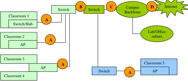
Since the bridging firewall is transparent, it is possible to install the bridge at virtually any place in the network. Figure 2 shows a conceptual campus network topology. In Figure 2, we show points A, B, C, and D. These are all good candidate locations at which to install a bridging firewall.
The flexibility of installing a bridging firewall at multiple points does not mean that each point is not without its own advantages and disadvantages. In selecting an installation point, the rule-of-thumb is to install the bridge at an aggregation point. In practice, there are usually several locations with different levels of aggregation. In Figure 2, Point D has the most amount of aggregation, and Point A has the least. The higher the aggregation level, the broader the network coverage. For example, if we choose to install the bridge at Point D, one single bridging firewall can cover all classrooms on the campus. But if we select Point A, a bridging firewall will only cover one or a few classrooms, thus we would need to deploy multiple bridging firewalls to achieve full coverage. On the other hand, the higher amount of aggregation we choose, the more impact on the rest of the network. For example, if we select Point D, not only are the classroom networks affected, but so are the lab and office networks. While most side effects can be corrected through specific rule sets, e.g., rules that consider the source of the packets and whether it is from a classroom or lab, such rule sets become more complicated and prone to error. Therefore, the installation decision needs to properly balance locality and simplicity. In a network like the one shown in Figure 2, Points B or C likely offer a good balance between these two factors.
AP Classroom 1 Switch/Hub Classroom 2 AP Classroom 3 Classroom 4 Switch Classroom 5 AP Campus Backbone Switch Lab/Office subnet Internet A Switch B C D A A A
Web-Based Control Panel
Although ebtables and iptables have a command line interface to manage firewall rules, they are not necessarily easy to use. The syntax is not particularly straightforward and requires a long time to learn. For example, the order of rules in a chain is critical. If the rules are configured improperly, the bridging firewall would behave incorrectly. It may either fail to block desired connections, or cause severe network connectivity problems. A non-professional user is very likely to have difficulty in setting accurate and effective firewall rules.
Since the bridging firewall used in a classroom is likely to be managed by an instructor, instead of a network administrator, we are obliged to provide a well-designed user interface to allow an instructor to easily manage the bridging firewall. To this end, we have designed a web-based user interface. In order to provide both simplicity and flexibility, we have implemented two levels for the user interface: a basic interface and then an advanced interface.
3b 3a
Figure 3. Basic interface of the web-based control panel.
Most of time, an instructor may only need the most basic functionality of the CNAC system, e.g., to temporarily turn network connectivity on/off, or to enable/disable all off-campus web traffic. These kinds of simple requests can be executed using the basic version of the interface with just a few clicks. Figure 3 shows the screenshots of the basic version of the control interface. Simplicity becomes the highest priority in designing the layout and functions. Figure 3a is the main page for the CNAC control panel. After login, the page lists all classrooms that are controllable. The instructor, after selecting the desired classroom, enters the classroom-specific page as shown in Figure 3b. The basic version of the interface is not intended to provide a full-fledged rules management platform; instead, it only provides a few fixed-access control templates. Currently we have four fixed connection types: “allow all traffic”, “allow web traffic only”, “allow on-campus traffic only”, and “block all traffic”. Of course, we can add more options as necessary, or as requested by an instructor.
In addition to the basic options, an instructor may want more finer-grained control. For example, during a lecture, an instructor may want to allow web traffic to and from the class web server, but disable all other web traffic. In this situation, either this option can be pre-configured and made available as a choice on the basic interface menu, or the instructor can use the advanced interface. The advanced interface mainly “wraps” iptables commands, and sends the commands to the bridging firewall. The advanced interface is more sophisticated and provides greater flexibility, but requires more knowledge about the proper construction of rules.
In either interface version, after the instructor selects the connection option, the web server invokes a script to execute the corresponding iptables/ebtables command in the bridging firewall. In order for the bridging firewall to receive the web-generated rules, the bridge must be assigned an IP address through which the web-server-side script sends the control commands. This IP address is used to communicate with the web server only. The IP address may or may not be associated with a particular bridge interface. If the IP address is not associated with either of the existing interfaces, a third NIC can be used. This additional interface provides additional flexibility and security.
Testbed Experiment
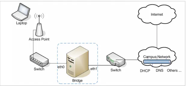
In order to test the correct operation of our CNAC system, we constructed a testbed to conduct a series of experiments. The testbed is shown in Figure 4. The two main goals of the experiments were to verify that (1) an Ethernet bridge is able to connect an initially isolated wireless LAN to a wired network, and (2) the firewall functions of the Ethernet bridge are able to control and filter certain types of Internet traffic.
Figure 4. Testbed environment.
In our experiments, we used a personal computer as the bridge. The computer had three NICs, named eth0, eth1
and eth2, respectively. The computer was installed with the Linux Fedora Core 4 with the 2.6.12 version of the operating system, and the bridge and netfilter modules were enabled. Eth0 and eth1 were associated with the bridge interface br0. Eth0, eth1, and br0 were not assigned IP addresses. Eth2 was assigned a fixed IP address, and this interface was used only for receiving web server-side script commands.
A laptop was used to generate “classroom traffic”. The laptop was configured to obtain its IP address using the Dynamic Host Configuration Protocol (DHCP). There was a DHCP server running in the department network, shown as part of the “campus network” in Figure 4. We conducted four sets of experiments.
• Test #1: the bridging firewall did not exist, i.e., the two switches were connected together directly. The laptop successfully obtained an IP address from the department DHCP server, and all traffic was successfully sent to and from the laptop.
• Test #2: the eth0 port of the bridging firewall was connected to the switch on the left side of Figure 4, and eth1 was connected to the other switch. The firewall rules were set to “block all traffic”. In this case, the laptop failed to obtain an IP address using DHCP, and all attempts to send or receive traffic were blocked.
• Test #3: the topology was the same as in Test #2, but the firewall rules were set to “allow all traffic”. The goal was to show that the bridging firewall could be made to have no effect. The result of the test was that traffic to and from the laptop behaved exactly as in Test #1.
• Test #4: the topology was the same as in Test #2, but the firewall rules were set to “allow secure shell (Port 22) traffic, DHCP, and DNS, but block all other traffic”. The laptop obtained an IP address, and was able to login to a remote computer, but all other traffic was blocked.
From these four tests, we are able to demonstrate that the bridging firewall operates as expected. Another series of tests that are left for future work are to measure the impact of using the bridging firewall, for example, whether key network metrics like delay, loss, and jitter are affected by the bridging firewall.
Conclusions
Computers and networks are entering more and more classrooms. In order to embrace new technology and the accompanying social shifts, we believe a classroom network monitoring and control system will benefit instructors, students, and researchers. In this paper, we have presented the simple but effective CNAC system. It is simple because the transparent and centralized bridging firewall makes installation easy. The control panel provides a simple user interface. It is effective because the bridging functions built into the Linux operating system are powerful and flexible enough to satisfy virtually any access control policy. The successful experiments we conducted show that CNAC functions as designed.
As for future plans, we plan to evaluate CNAC’s network performance in real classroom environment. Furthermore, there is a potential limitation when CNAC is used in certain kinds of wireless networks, e.g. when the radio coverage for an 802.11a/b/g access point covers more than one classroom. In Figure 2, Classrooms 3 and 4 are covered by the same AP; hence, Classrooms 3 and 4 are in the same logical LAN. In this case, the bridging firewall does not have enough information to distinguish which computers are in which classroom. To solve this problem, we will need to utilize lower layer MAC address information to establish a student-to-MAC-address mapping table. By examining the MAC address, the bridging firewall can identify which student is associated with each address. Finally, we plan to add a calendaring system to CNAC so that certain rule sets can be configured to automatically run at specific times. This feature will enable different classes to be configured automatically.
References
Anderson, R., Simon, B., Wolfman, S., VanDeGrift, T. & Yasuhara, K. (2004). Experiences With a Tablet PC Based Lecture Presentation System in Computer Science Courses. SIGCSE Technical Symposium on Computer Science Education, Norfolk, Virginia, March 2004, 56-60.
Anderson, R., VanDeGrift, T., Wolfman, S. & Yasuhara, K. (2003). Promoting Interaction in Large Classes with Computer-Mediated Feedback. Computer Support for Collaborative Learning, Bergen, Norway, June 2003, 119-123.
Bridging, ebtables and iptables. http://www.linuxsecure.de/index.php?action=90/. (Last accessed in December 2005). Calhoun, P., O'Hara, B., Kelly, S., Suri, R., Williams, M. & Hares, S. (2005). Light Weight Access Point Protocol (LWAPP).
IETF Internet-Draft, March 2003.
Campbell, A. & Pargas. R. (2003). Laptop in the Classroom. SIGCSE technical symposium on Computer science education, Reno, Navada, February 2003, 98-102.
Ebtables. http://ebtables.sourceforge.net/. (Last accessed in December 2005).
Efaw, J., Hampton, J., Martinez, J. & Smith, S. (2004). Miracle or Menace: Teaching and Learning with Laptop Computers in the Classroom. Educause Quarterly, 27 (3).
Enterasys. http://www.enterasys.com/solutions/education/prof/. (Last accessed in December 2005).
Fisher, D. & Stolarchuk, E. (1998). The effect of Using Laptop Computers on Achievement, Attitude to Science and Classroom Environment in Science. Western Australian Institute for Educational Research Forum, 1998.
Linux Ethernet Bridge Project. http://linux-net.osdl.org/index.php/Bridge. (Last accessed in December 2005). McWilliams, G. (2005). Laptops in Classrooms Not Working Out As Hoped. The Wall Street Journal. October 2005.
Moody, L. & Schmidt, G. (2004). Going wireless: The Emergence of Wireless Networks in Education. Journal of Computing Sciences in Colleges, 19(4), 151-158.
Netfilter and Iptables: http://www.netfilter.org/. (Last accessed in December 2005).
Robinson, J. (2005). Operating system Korner: Linux as an Ethernet Bridge. Linux Journal, 2005(135), 11.
Ryder, J. (2000). Universal computer access for students – a classroom experiment in computer science. Journal of Computing Sciences in Colleges, 15(5), 52 – 60.
Singh, G., Denoue, L. & Das, A. (2004). Collaborative Note Taking. Proceedings of the IEEE International Workshop on Wireless and Mobile Technologies in Education, March 2004, 163-167.
Yancy, D. (2001). Classroom Network Control System. Educause Quarterly, 2001.
Yang, L., Zerfos, P., & Sadot, E. (2005). Architecture Taxonomy for Control and Provisioning of Wireless Access Points (CAPWAP). IETF Internet-Draft. November 2005.