2013
Cyber security of the smart grid: Attack exposure
analysis, detection algorithms, and testbed
evaluation
Adam Hahn
Iowa State University
Follow this and additional works at:https://lib.dr.iastate.edu/etd
Part of theComputer Engineering Commons, and theLibrary and Information Science Commons
This Dissertation is brought to you for free and open access by the Iowa State University Capstones, Theses and Dissertations at Iowa State University Digital Repository. It has been accepted for inclusion in Graduate Theses and Dissertations by an authorized administrator of Iowa State University Digital Repository. For more information, please [email protected].
Recommended Citation
Hahn, Adam, "Cyber security of the smart grid: Attack exposure analysis, detection algorithms, and testbed evaluation" (2013).
Graduate Theses and Dissertations. 13098. https://lib.dr.iastate.edu/etd/13098
algorithms, and testbed evaluation
by
Adam Lee Hahn
A dissertation submitted to the graduate faculty in partial fulfillment of the requirements for the degree of
DOCTOR OF PHILOSOPHY
Major: Computer Engineering
Program of Study Committee: Manimaran Govindarasu, Major Professor
Venkataramana Ajjarapu Thomas Daniels
Doug Jacobson Johnny Wong
Iowa State University Ames, Iowa
2013
TABLE OF CONTENTS
LIST OF TABLES . . . vi
LIST OF FIGURES . . . vii
ACKNOWLEDGEMENTS . . . ix
ABSTRACT . . . x
CHAPTER 1. INTRODUCTION . . . 1
1.1 The smart grid . . . 2
1.2 Growing threats within cyberspace . . . 4
1.3 Vulnerabilities within the smart grid . . . 6
1.4 Research needs . . . 10
1.5 Thesis contributions . . . 11
CHAPTER 2. SMART GRID BACKGROUND AND LITERATURE SURVEY . . . 13
2.1 Traditional electric grid overview . . . 13
2.1.1 Generation . . . 15
2.1.2 Transmission . . . 15
2.1.3 Distribution . . . 16
2.1.4 Markets and system operators . . . 16
2.1.5 SCADA architectures . . . 16
2.2 Smart grid technologies and communications . . . 20
2.2.2 Substation automation systems . . . 25
2.2.3 WAMS . . . 31
2.2.4 CIM . . . 32
2.3 Cyber threats to the smart grid . . . 33
2.3.1 Communications . . . 34
2.3.2 Systems and devices . . . 36
CHAPTER 3. CYBER ATTACK EXPOSURE EVALUATION FRAME-WORK . . . 38
3.1 Introduction . . . 38
3.2 Related work . . . 39
3.2.1 Attack surface analysis . . . 39
3.2.2 Attack trees . . . 40
3.2.3 Privilege/attack graphs . . . 40
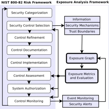
3.3 Exposure evaluation framework . . . 41
3.3.1 Identifying cyber risk . . . 42
3.3.2 Exposure graph development . . . 47
3.3.3 Exposure evaluation . . . 48
3.4 Exposure metric applications . . . 49
3.4.1 Vulnerability analysis . . . 50
3.4.2 Cyber security investment optimization . . . 51
3.4.3 Cyber contingency analysis . . . 51
3.5 Metrics evaluation . . . 53
3.5.1 Simulated environment . . . 53
3.5.2 Simulation Results . . . 55
CHAPTER 4. MODEL-BASED HIERARCHICAL INTRUSION DE-TECTION FOR THE SMART GRID (MHINDS) . . . 59
4.2 Related work . . . 60
4.2.1 Misuse-based IDS . . . 61
4.2.2 Anomaly-based IDS . . . 62
4.2.3 Specification-based IDS . . . 62
4.2.4 Model-based IDS . . . 63
4.3 Threats to substation automation functions . . . 63
4.3.1 Protection schemes . . . 64
4.3.2 Threat model . . . 66
4.4 MHINDS detection methodology . . . 66
4.4.1 Substation level detection . . . 67
4.4.2 System level detection . . . 74
4.4.3 Security analysis and evaluation . . . 77
CHAPTER 5. CPS SECURITY TESTBED FOR THE SMART GRID 84 5.1 Introduction . . . 84
5.2 Related work . . . 85
5.3 Testbed research applications and design . . . 87
5.3.1 Research applications . . . 88
5.3.2 Testbed design elements . . . 92
5.4 ISU’s PowerCyber testbed architecture . . . 95
5.4.1 Control . . . 95
5.4.2 Communication . . . 96
5.4.3 Physical system . . . 98
5.5 Testbed evaluation and experimentation . . . 99
5.5.1 Vulnerability assessment . . . 99
5.5.2 Cyber-physical impacts . . . 99
CHAPTER 6. CONCLUSION AND FUTURE WORK . . . 110
APPENDIX
PUBLISHED WORK . . . 114
LIST OF TABLES
Table 1.1 Roadmaps and security guidelines for cyber security concerns . . 9
Table 2.1 Smart grid communications (I: Integrity, A: Availability, C: Con-fidentiality) . . . 21
Table 2.2 Sample of IEC 61850 LN names and definitions . . . 26
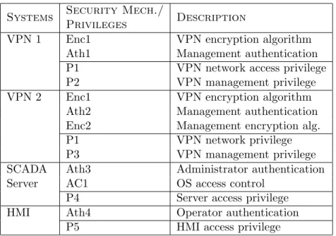
Table 3.1 Example security mechanisms and privileges . . . 45
Table 3.2 Example security mechanism for an AMI architecture . . . 52
Table 3.3 Example set of information objects . . . 54
Table 4.1 MHINDS Petri net places . . . 69
Table 4.2 Detectability of IED malicious control operations . . . 73
Table 4.3 Line and bus protection systems and relays . . . 76
Table 5.1 Research efforts to testbed capability mapping . . . 89
Table 5.2 Evaluated cyber attacks . . . 100
LIST OF FIGURES
Figure 1.1 Power system domains[34] . . . 6
Figure 2.1 Schematic of the smart grid cyber infrastructure . . . 14
Figure 2.2 Commodity vs. SCADA-specific ICT . . . 19
Figure 2.3 61850 control operation . . . 28
Figure 2.4 61850 protection operation . . . 29
Figure 2.5 61850 breaker failure operation . . . 30
Figure 2.6 Attacks to the smart grid . . . 34
Figure 3.1 Attack exposure evaluation framework . . . 42
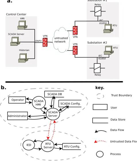
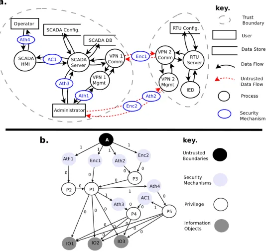
Figure 3.2 a) Testbed network architecture, b) Testbed data flow diagram . 43 Figure 3.3 a) Testbed DFD with security mechanisms, b) Resulting exposure graph . . . 46
Figure 3.4 Exposure metric applications . . . 50
Figure 3.5 Simulation AMI use cases . . . 53
Figure 3.6 Exposure metrics for normal/vulnerable scenarios . . . 55
Figure 3.7 Exposure after security enhancements . . . 57
Figure 4.1 Traditional IT and smart grid IDS approaches . . . 60
Figure 4.2 Threats against grid security and reliability . . . 66
Figure 4.3 MHINDS architecture and logical functionality . . . 67
Figure 4.4 Substation Petri net model . . . 69
Figure 4.6 Power system protection configuration [61] . . . 75
Figure 4.7 Probability of failures in protection scheme operations . . . 79
Figure 4.8 Max. relay pickups to ensure< 5% false positives . . . 80
Figure 4.9 Attacks required to spoof protection operation . . . 81
Figure 4.10 Relay detectable vs undetectable attacks . . . 82
Figure 4.11 Substation detectable vs undetectable attacks . . . 83
Figure 5.1 Testbed applications . . . 85
Figure 5.2 Logical testbed architecture . . . 92
Figure 5.3 PowerCyber testbed architecture . . . 94
Figure 5.4 Generator rotor angles . . . 101
Figure 5.5 DoS impact on control system communication . . . 102
Figure 5.6 RAS physical and cyber system . . . 103
Figure 5.7 DoS protection scheme impact (switch flooding) . . . 105
Figure 5.8 DoS protection scheme impact (relay Syn flood) . . . 106
Figure 5.9 Impact of attack on system voltages . . . 109
ACKNOWLEDGEMENTS
I’d first like to express my thanks to Manimaran Govindarasu for accepting me as a student, providing support for my time as a graduate student, and investing countless hours into my professional development. His motivating personality was fundamental to my success in the Ph.D. program and pushed me far beyond my own expectations.
I’d like to thank Doug Jacobson and Thomas Daniels. They taught my first courses in Information Assurance, were members of my Masters thesis committee years ago, and continued to provide support and encouragement throughout my Ph.D. program. In addition, I’d like to express my appreciation to Venkataramana Ajjarapu and Johnny Wong for their valued contributions to my research as members of my committee.
I’d also like to thank my fellow graduate students, especially Siddharth Sridhar, Aditya Ashok, and Benazir Fateh. Both Siddharth’s and Aditya’s expertise in power systems has been invaluable to my research. They significantly contributed to my under-standing of basic power system operations and future smart grid initiatives. Addition-ally, I’d like to acknowledge Siddharth’s and Aditya’s assistance in the development of the PowerCyber testbed, specifically their help in developing power system simulations, evaluating attack impacts to the physical grid, and helping debug endless technical is-sues. I’d also like to thank Benazir for her many engaging conversations about research, coursework, and running.
Last, but not least, I’d like to thank all of my family and friends whose continual support was paramount to this work. Specifically, Mom and Dad for their tolerance of my continual frustrations. I’d also like to thank the rest of my amazing family, especially Emily, Sam, John, Amy, Max, and Issac for their perpetual encouragement.
ABSTRACT
While smart grid technologies are deployed to help achieve improved grid resiliency and efficiency, they also present an increased dependency on cyber resources which may be vulnerable to attack. This dissertation introduces three components that provide new methods to enhancing the cyber security of the smart grid.
First, a quantitative exposure analysis model is presented to assess risks inherited from the communication and computation of critical information. An attack exposure metric is then presented to provide a quantitative means to analyze the model. The metric’s utility is then demonstrated by analyzing smart grid environments to contrast the effectiveness of various protection mechanisms and to evaluate the impact of new cyber vulnerabilities.
Second, a model-based intrusion detection system is introduced to identify attacks against electric grid substations. The system expands previous research to incorporate temporal and spatial analysis of substation control events in order to differentiate attacks from normal communications. This method also incorporates a hierarchical detection approach to improve correlation of physical system events and identify sophisticated coordinated attacks.
Finally, the PowerCyber testbed is introduced as an accurate cyber-physical envi-ronment to help facilitate future smart grid cyber security research needs. The testbed implements a layered approach of control, communication, and power system layers while incorporating both industry standard components along with simulation and emulation techniques. The testbed’s efficacy is then evaluated by performing various cyber attacks and exploring their impact on physical grid simulations.
CHAPTER 1.
INTRODUCTION
Dependencies on Information and Communication Technology (ICT) have propagated throughout our modern society. While these technologies present resounding benefits across commercial, government, academic, and personal ventures their usage is contin-ually hindered by our inability to engineer systems with adequate levels of security. Malicious actors have continually abused security weaknesses by stealing confidential data, compromising data integrity, and degrading system availability.
Critical infrastructure domains, such as transportation, chemical, medical, and energy have also greatly benefited from ICT as a means to monitor and control various physical domains. However, a successful attack against critical infrastructure may result in a catastrophic impact to the economy, natural resources, and even human safety. These systems often were not engineered to provide the robust levels of security needed to protect against an increasingly hostile cyberspace. In addition, there is a current trend to expand the connectivity of many critical infrastructure systems to provide improved control and monitoring capabilities.
While all critical infrastructure domains inherit some risk from cyber attack, the electric power grid is likely the most critical and vulnerable of these domains. The electric grid is a core foundation of our modern society and is imperative for the operation of all other critical infrastructure sectors. The grid is also more exposed to cyber attack than many domains due to its large number of involved parties, primarily private ownership, and heavily interconnected communications which leave it exposed to attack. In addition, the grid is particularly vulnerable to large cascading failures due to physical phenomena.
However, a cyber attack could potentially initiate equivalent failures.
While the electric grid has long been dependent on ICT to manage the various com-ponents of the generation, transmission, and distribution systems, current smart grid
initiatives are focusing on expanding the use of ICT to modernize the current grid. How-ever, this expanded use of ICT will lead to a greater attack surface which presents a currently undetermined level of risk.
1.1
The smart grid
The U.S. Department of Energy (DOE) has identified seven properties required for a next generation power grid including attack resistance, self-healing, consumer motiva-tion, power quality, generation and storage accommodamotiva-tion, enabling markets, and asset optimization [104]. Smart grid technologies are being used to enhance all areas of the electric grid, including the generation, transmission, distribution, and markets. Many of these advances are enabled by continually improving communication and information processing capabilities. The remainder of this section identifies smart grid initiative impacts which cause significant influences on the use of ICT within the grid.
Advanced Metering Infrastructure (AMI): AMI enhances electricity
distribu-tion by deploying smart meters at consumer locadistribu-tions with a goal to reduce cost, in-crease electricity reliability, and support distributed generation. These meters provide the customer with granular control over their consumption and also facilitate increased integration of Distributed Energy Resources (DER). Utilities benefit from being able to remotely detect outages, perform remote meter readings and offer prepaid options to customers. AMI also enables Demand Side Management (DSM) which exercises di-rect/indirect control over consumer power consumption.
Wide Area Measurements Systems (WAMS): Increased grid monitoring
systems. WAMS are predicated upon Phasor Measurement Units (PMU), which pro-vide high sampling rates and accurate GPS-based timing to enable highly accurate and synchronized phasor readings. While the deployment of PMUs provides increasingly accurate readings, the full potential will not be realized unless these readings can be shared among utilities and regulators. Additionally, power system applications must be reviewed and redeveloped to determine the extent these granular readings may provide to both grid efficiency and reliability. The development of advanced control applications will depend on WAMS that will effectively distribute the information in a secure and reliable manner.
Substation automation systems: To improve the performance and reliability
of device communication within substations, new communications paradigms are being deployed. Older substations often utilized point-to-point communications and serial (RS-232) physical layers. Newer substations deploy faster Ethernet networks which allow multicast transmission of device status to provide real-time awareness of all substation events. Improved field devices, such as Intelligent Electronic Devices (IEDs), can be deployed to perform more sophisticated operations, such as grid protection schemes.
Common Information Models (CIM): The smart grid will also increase the use
of CIMs to provide a common format for expressing and communicating the information required to support the grid [42]. As the interconnectivity of smart grid systems increase, CIMs will ensure the interoperability of these communications. Current CIM standards such as IEC 61968, which primarily focus on distribution systems, and IEC 61970 for transmission systems, are represented as an ontology that formalizes the information and relationships necessary to support the grid [73]. CIMs have been primarily developed to facilitate increased system integration through consistent data representation and exchange formats.
1.2
Growing threats within cyberspace
Early computing technologies such as multi-user systems and networking created a need for secure computer platforms. Since this time, both threats and cyber dependencies have continued to evolve. The 1980’s presented the Morris worm, which was the first example of self-propagating malicious software. This occurrence became prevalent in the 1990’s and early 2000’s with malware such as Slammer and Conficker which infected large numbers of systems and inflicted a substantial economic burden to the victims [90][77].
While many of the early computer worms did not intentionally damage the infected systems, more recently attacks have been used as a means to gain political and economical advantage. In 2007 and 2008, sophisticated Denial of Service (DoS) attacks were launched against the countries of Georgia and Estonia as a means to influence political agendas [100].
While the large scale DoS attacks required highly skilled attackers, recent events sug-gest the presence of increasingly sophisticated attackers. Attacker campaigns identified by high sophistication, determination, and financial support have been coined Advanced Persistent Threat (APT) [43]. Intrusions such as Operation Aurora and Operation Shady RAT represent to specific examples of APT type capabilities. Operation Aurora targeted many large technology companies, such as Google, and exfiltrated large amounts of in-tellectual property [70]. Operation Shady RAT demonstrated similar capabilities and targeted over 70 companies and governments over a five year period [3].
As our nation’s dependency on cyber infrastructure grows, these systems become an increasingly attractive target for well funded nation-state attackers. Many nations are focusing on the development of cyber-based military capabilities [49]. For example, a 2009 report by the U.S.-China Economic and Security Review Commission claimed that China’s People’s Liberation Army (PLA) sponsors cyber attacks targeting U.S. systems, specifically focusing on espionage of military secrets [108]. Similar claims have been
asserted by a recent report by Mandiant which identifies the PLA as the party respon-sible for the infiltration of over 150 U.S. companies for the purpose of stealing valuable intellectual property and other corporate secrets. The report specifically identifies Chi-nese locations, military branches, and even the individuals responsible for many of these attacks [65].
While the efforts of the PLA cyber capabilities are heavily documented, many other sophisticated attacks have been identified within the past few years which suggest nation-state involvement. Malware samples such as Stuxnet, Duqu, Flame, Gauss, and Shamoon all include many advanced features which suggest nation-state involvement [26][11]. While the objectives of Duqu, Flame, and Gauss focus on traditional espionage ob-jectives, Stuxnet presented a foundational shift in malware with its ability to usurp the operation of an Industrial Control System (ICS).
Recent surveys have suggested that most critical infrastructure asset owners have been targeted by some form of cyber attack [6]. However, Stuxnet remains the first example of a sophisticated attack targeting the physical domain. Stuxnet’s key salient feature is its ability to propagate malware into a control system and reconfigure the Pro-grammable Logic Controllers (PLC) to perform potentially harmful actions [36]. While it is speculated that Stuxnet targeted Iranian nuclear refinement facilities in order to damage Uranium centrifuges, a similar attack approach could likely be used to target other critical infrastructures in many domains, including the electric power grid, which depends heavily on similar PLCs.
The U.S. government has recently identified the gravity of the these concerns. Efforts such as Homeland Security Presidential Directive 7 (HSPD-7) have prioritized the pro-tection of critical infrastructures, including the electric power grid [112]. Additionally, the 2013 White House Executive Order, titled “Improving Critical Infrastructure Cy-bersecurity” emphasizes the need for improved cyber security of critical infrastructure, specifically identifying requirements for a “framework to reduce cyber risk to critical
Figure 1.1 Power system domains[34]
infrastructure” and “information security measures and controls, to help owners and operators of critical infrastructure identify, assess, and manage cyber risk” [113].
1.3
Vulnerabilities within the smart grid
The combination of an increasingly interconnected smart grid and growing sophis-tication of cyber threats presents concerns for the grid’s current security posture. As demonstrated in Figure 1.1, threats could target the generation, transmission, distribu-tion, and market domains. In addidistribu-tion, each domain not only has a set of core operational assets to defend, but must also be concerned with the exposure of their critical business and corporate environments.
Unfortunately, as cyber security concerns have grown, researchers have begun to identify many critical vulnerabilities within the communication protocols and software platforms used to support the electric grid. Analysis performed by the Department of Homeland Security (DHS) and Idaho National Laboratory (INL) have determined that serious vulnerabilities are pervasive throughout ICS software platforms and network
con-figurations [45, 46]. Additionally, the U.S. Government Accountability Office (GAO) has reported that these system lack relevant patches, maintain poor system configurations, provide insufficient communication protection, and face a dearth of appropriate intrusion detection capabilities [106][105].
Based on these findings, more secure systems must be developed to provide sufficient resiliency to cyber attack. Although a wealth of research has been performed address-ing traditional cyber security paradigms, many solutions do not adequately address the additional constraints required to support the electric grid. The following list identifies known constraints which result in deficient smart grid cyber security.
• Long system lifespans. Unlike more traditional IT systems, many systems within the smart grid will be deployed for 10-20 years. This means more secure systems cannot be deployed as cyber threats evolve.
• Heavy dependency on proprietary systems. Most proprietary systems do not have well understood operations, which leaves the owners unable to make intelligent decisions concerning their risk and what security mechanisms are appropriate to protect them.
• Geographically disperse resources. Systems are strongly dependent on wide area networks, which are more vulnerable to external attacks.
• Limited physical protections. Many systems are physically exposed, such as sub-stations. This leaves them more vulnerable to physical tampering.
• Real-time requirements. Many security mechanisms, such as cryptography, cause unacceptable overhead on the communication. Therefore, systems with real-time requirements often cannot adopt many security controls.
• Restricted use of “fail-closed” security mechanisms. Systems need to be accessible by operators in critical situations and, therefore, cannot restrict access to operators
if they are unable to authenticate.
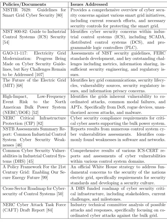
The previously identified concerns have been recognized by both the U.S. government and electric industry. Table 1.1 identifies roadmaps and security guidelines addressing smart grid cyber security. There have been multiple initiatives by both parties to at-tempt to improve the security. For example, the National Institute for Standards and Technology (NIST) published the “Guide to Industrial Control Systems (ICS) Security” specifically identifying threats, vulnerabilities, and security controls required to provide a robust cyber infrastructure [54]. Acknowledging future demands for both cyber security and privacy for smart grid initiatives, NIST has released the NISTIR 7628, “Guide-lines for Smart Grid Cyber Security” document to provide future guidance as cyber assets proliferate throughout the electric grid [80]. This document identifies likely cyber architectures, enumerates required research initiatives, and documents critical security controls.
In the private sector, the North American Electric Reliability Corporation (NERC) has also acknowledged the threat to the electric grid. In 2009 they released the “High-Impact, Low-Frequency Event Risk to the North American Bulk Power System” report which enumerated major threats to the grid, specifically those from coordinated attacks which blend cyber and physical methods [52]. Additionally, NERC created a Cyber Attack Task Force (CAFT) to explore cyber vulnerabilities in the grid and identify feasible detection, deterrence, and response capabilities [84]. NERC also developed and enforces a set of of Critical Infrastructure Protection (CIP) standards which require the identification and protection of all cyber assets supporting the bulk power system [82].
Table 1.1 Roadmaps and security guidelines for cyber security concerns
Policies/Documents Issues Addressed
NISTIR 7628: Guidelines for Smart Grid Cyber Security [80]
Provides a comprehensive overview of cyber secu-rity concerns against various smart grid initiatives, including current research efforts, and necessary security controls for protecting the smart grid. NIST 800-82: Guide to Industrial
Control Systems (ICS) Security [54]
Identifies cyber security concerns within indus-trial control systems (ICS), including SCADA, distributed control systems (DCS), and pro-grammable logic controllers (PLC).
GAO-11-117: Electricity Grid Modernization: Progress Being Made on Cyber Security Guide-lines, but Key Challenges Remain to be Addressed [107]
Assessments of NIST security guidelines, FERC standards development, and key outstanding chal-lenges including metrics, information sharing, in-sufficient security engineering, and regulatory is-sues.
The Future of the Electric Grid (MIT) [68]
Identifies key grid communications, security lifecy-cles, vulnerability sources, security regulatory is-sues, and information privacy concerns.
High-Impact, Low-Frequency Event Risk to the North American Bulk Power System (NERC/DOE) [52]
Identifies the grids inherent vulnerability to co-ordinated attacks, common modal failures, and APTs. Specifically from DoS, rogue devices, unau-thorized access attacks, and malware.
NERC Critical Infrastructure Protection (CIP) [82]
Cyber security compliance requirements for criti-cal cyber assets supporting the bulk power system. NSTB Assessments Summary
Re-port: Common Industrial Control System Cyber Security Weak-nesses [46]
Reports results from numerous control system cy-ber vulnerabilities assessments. Identifies com-monly found weaknesses in software and networks. Common Cyber Security
Vulner-abilities in Industrial Control Sys-tems (DHS) [45]
Comprehensive results of various ICS-CERT re-ports and assessments of cyber vulnerabilities within various control system domains.
A Policy Framework For the 21st Century Grid: Enabling Our Se-cure Energy Future [99]
An official White House strategy to address fun-damental concerns to the security of the nations electric grid, specifically requirements for security standards and developing a security culture. Cross-Sector Roadmap for
Cyber-security of Control Systems [50]
A DHS funded roadmap of cyber security criti-cal infrastructure, including stakeholders, current challenges, and milestones.
NERC Cyber Attack Task Force (CAFT) Draft Report [84]
Industry technical committee analysis of possible attacks and responses, specifically focusing on co-ordinated cyber attacks against the bulk grid.
1.4
Research needs
The development of a secure smart grid requires a vast amount of research in many domains. While many security technologies are available for traditional ICT systems, they frequently aren’t usable for smart grid applications due to excessive overhead or concerns that they may prevent an operator from accessing certain critical functions. Therefore, novel approaches must be explored for these technologies. Additionally, cyber security must be addressed from a cyber-physical perspective, thereby analyzing how the grid’s physical systems attributes influence the need for security and tailors the approaches to security. This research focuses on the latter point, specifically identifying the following three core research needs.
1. Models and metrics for the smart grid cyber security which incorporate:
• the ability to quantify risk to a system,
• incorporates current smart grid information models, and
• provides flexibility for both known and unknown vulnerabilities.
2. Tailored intrusion detection approaches which:
• integrated with smart grid communication protocols,
• incorporates awareness of both cyber and physical anomalies, and
• enables the analysis of sophisticated, coordinated attacks.
3. Smart grid research testbeds that:
• accurately integrate both cyber and physical system properties,
• provides environments to explore cyber vulnerabilities and physical system impacts, and
1.5
Thesis contributions
This dissertation is structured as follows:
• Chapter 2 provides an overview of smart grid technologies and a background of related work for this dissertation. The smart grid overview identifies how the grid currently uses ICT to perform monitoring and control functions. It then introduces new smart grid technologies and provides an overview of cyber attacks and how they may impact the grid.
• Chapter 3 introduces work done on the development of security models and met-rics specifically tailored for the smart grid. It first presents a graph-based model representing the security mechanisms which protect the grid’s critical data from attacks. Then it computes anexposure metric which represents the level of protec-tion for each data item. It then demonstrates the metric’s applicability to various security decisions such as analyzing the impact of a vulnerability and evaluating the efficacy of different security mechanisms.
• Chapter 4 identifies novel approaches to intrusion detection for the smart grids. It demonstrates how attacks to the smart grid differ from traditional attacks by also incorporating smart grid commands. It then demonstrates how a Petri net model can be used to identify whether a device causes a malicious communication by modeling the set of preconditions necessary for an event. It then demonstrates how events can be correlated hierarchically to more accurately analyze events.
• Chapter 5 presents the contributions in the development of a smart grid cyber-physical security testbed. It introduces various research applications which depend on testbeds and analyzes various trade-offs in testbed designs. It then provides an overview of the development of the PowerCyber testbed. Finally, it demonstrates
the testbed’s utility with the execution of various integrity and availability attacks which are then analyzed in terms of their impact on grid stability.
CHAPTER 2.
SMART GRID BACKGROUND AND
LITERATURE SURVEY
The smart grid will combine both traditional electric grid control functions with cutting edge technologies. Fig. 2.1 provides a high-level overview of the smart grid including the various domains and systems found within it. This chapter provides an introduction to the smart grid, known cyber vulnerabilities, and related research to this work. It will first introduce the foundational domains of the electric power grid and provide an overview of the SCADA architectures currently used to perform monitoring and control. It then introduces various smart grid initiatives including AMI, WAMS, CIM, and substations automation enhancements. The chapter then identifies the various protocols used to support the various communications requirements and identifies various cyber attacks that could be used by a malicious individual to damage the smart grid. Finally, it presents a literature survey of works related to this dissertation.
2.1
Traditional electric grid overview
The electric grid can divided into four core domains, generation, transmission, distri-bution, and third parties, such as markets and system regulators. These domains have all been dependent on various ICT systems to support communication with other sys-tems within the domain and externally. This section will explain each domain in greater detail, along with the traditional Supervisory Control And Data Acquisition (SCADA) architecture used to support the communication and computation requirements
Figure 2.1 Sc hematic of the smart grid cyb er infrastructure
2.1.1 Generation
The generation domains focuses on the production of electricity. Electricity genera-tion is primarily done with a spinning turbine; therefore, most of the control algorithms focus on managing the frequency, voltage, and power output of the generator. Multiple control systems are required to support these algorithms. Local control systems include Governor Control, which is used to control the generator’s frequency, and Automatic Voltage Regulator (AVR), which is used to control the generator’s reactive power. In ad-dition to these local control systems, generation must also communicate with third-party balancing authorities to ensure each remains appropriately synchronized. The wide-area Automatic Generation Control (AGC) is used to perform this function by monitoring and adjusting a generator’s frequency as loads change. In addition, generation systems also must implement various protection algorithms to prevent against any physical faults which may occur. This system is explained in more detail in Section 2.2.2.
2.1.2 Transmission
The transmission domain focuses on the transportation of high-voltage electricity from large generators to the distribution domain. Control over the operation of the transmission systems primarily occurs within substations where power lines intercon-nect. Substations primarily support needs to convert power between different voltages on neighboring lines and also provide a place to deploy various control mechanisms. Transmission lines must be continually monitored to ensure that the load on the lines does not surpass their physical limitations. This is performed with state estimation con-trol algorithms, which is a wide-area monitoring system that collects telemetry from power lines and transmits them back to the control center where they are used to cal-culate the flow on the transmission system. Additionally, protection systems are very important in transmission because the lines are physically exposed and are frequently impacted by faults which perturb power flow. Protection schemes are implemented in
both wide and local forms.
2.1.3 Distribution
The distribution domain focuses on transporting electricity from the transmission lines to the consumer through lower voltage lines. Distribution systems have traditionally had less automation than the transmission and generation domains. Traditionally, load shedding has been a primary control function within distribution, which uses breakers to trip relays on distribution feeders. Similar to the generation and transmission domains, the protection systems are heavily used within distribution systems to protect equipment from faults.
2.1.4 Markets and system operators
There are many other functions which are critical to the grid’s daily operations. Specifically, the oversight and management of the various utilities. Independent System Operators (ISO) are authoritative parties that coordinate the generation and transmis-sion amongst multiple utilities to ensure that load remains balanced. ISO also provide markets that are used to balance the supply and demand of electricity between energy producers and consumers. While the systems used to support these functions do not perform control functions, they are critical for the grid’s daily operation.
2.1.5 SCADA architectures
The power grid has historically been dependent on SCADA technologies to perform monitoring, alarms, and control functions throughout the generation, transmission, and distribution domains. SCADA systems utilize a hierarchical paradigm where a central-ized control center manages many geographically distributed field devices [54].
2.1.5.1 Control centers
Control centers provide a central location for analysis and control over some section of the grid, whether it be generation, transmission, or distribution. The control center is typically staffed with operators that make human-in-the-loop control decisions over many grid control functions. Control centers typically include the systems identified below.
SCADA servers - SCADA servers manage the telemetry and control operations
between the control center and the field devices within the various substations. SCADA servers are a critical component as they have the ability to send commands to the remote field devices and are the central means for operators to evaluate the state of the network. To obtain telemetry data, the SCADA server continually polls the field devices for state updates. This collected information can then be shared with other SCADA systems such as the EMS and Historian. Additionally, the SCADA server can also process any alarm data correlating to any anomalous physical events.
Energy Management Systems (EMS)- An EMS utilizes SCADA data to perform
higher level analysis of a system state to analyze potential problems and mitigations. Specifically, EMS are often used to execute generation control, state estimation, fault location algorithms and contingency analysis.
Human Machine Interfaces (HMI) - HMIs provide an interface between the
operator and the SCADA and EMS systems. The HMI is typically a graphical user interface (GUI) based interface that presents operators with the ability to analyze and control the states of various system components.
Historian - A historian is a system which contains a database of events which oc-curred on the physical system. The system is primarily used to analyze events off-line and generally is not used for real-time functions like the other previously identified systems. Control centers are dependent on both local and wide area communications. Local Area Networks (LAN) support communications between all the control center devices.
In addition, Wide Area Networks (WAN) are used to support communication between the SCADA server and the various substations. These WAN connections are primarily used to transmit the telemetry data and commands. Various forms of physical media are used for this communication, however, these often consist of leased lines and wireless microwave links. In addition, control centers often support some communication to non-operational business systems in order to provide awareness about system operations to other corporate entities.
2.1.5.2 Substations
Substations are where the SCADA technologies actually acquire the telemetry and send commands to the various field devices to control the physical grid. Therefore, these field devices provide the primary bridge between the grid’s cyber and physical domains. Field devices typically include PLCs, Remote Terminal Units (RTU), and IEDs.
PLC - PLCs are legacy devices which typically execute some form of programmable
latter logic to control some physical systems. Often these devices have very limited
communication and processing capabilities. These are often implemented as relays in control systems.
RTU- RTUs are also legacy devices which were developed to support communication needs between field devices such PLCs and some other controller. Therefore, these devices should have some ability to communicate over a network to support various control requirements.
IED - While substations historically used PLCs and RTUs to obtain telemetry and control actuators, recent trends are towards IEDs which have more capable computation and communication capabilities. IEDs are currently heavily deployed to perform many different functions such as controlling protection schemes and relaying telemetry from power lines along with send device statuses.
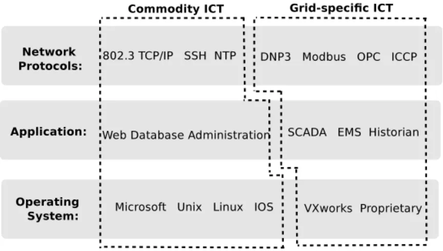
Figure 2.2 Commodity vs. SCADA-specific ICT
Substation Automation (SA) Systems - Modern substations also implement
some SA system which provides a central system to manage the various IEDs, PLCs, and RTUs found within the substation. In addition to providing a central control point, these systems may also provide a human operator with a local interface to the substations.
2.1.5.3 Software platforms and communication protocols
While SCADA systems require many tailored communication protocols and software platforms, they also incorporate many shared elements with traditional ICT systems as demonstrated in Fig. 2.2. SCADA communication protocols are tailored toward trans-mitting commands and telemetry data which requires strong availability and integrity. Common protocols used within the traditional power grid include Modbus, Distributed Network Protocol (DNP), Object Linking and Embedding (OLE) for Process Control (OPC), and Inter-Control Center Communications Protocol (ICCP).
In addition to the tailored SCADA protocols, many standard ICT protocols are also used to provide auxiliary services. Lower level protocols such as Ethernet and Internet Protocol (IP) are common to provide the ability to route packets between networks. Additionally, many higher level protocols are required to support both operations and administrative functions. For example, Network Time Protocol (NTP) is used to ensure
that all systems have synchronized clocks which is imperative when transmitting teleme-try data. Additionally, many administrative and management protocols are needed, such as Telnet, File Transfer Protocol (FTP), Simple Network Management Protocol (SNMP), and Transport Layer Security (TLS).
In addition to the tailored software used for the power grid, these systems all cur-rently depend on many standard platforms and communications found in ICT. Many SCADA specific software products exist which incorporate the various protocols which were previously identified. However, these products are often dependent on many com-modity operating systems and services to support the SCADA applications. Comcom-modity operating systems such as Microsoft Windows and many Unix derivatives are commonly used along with many different embedded operating systems. In addition, these software platforms are also heavily dependent on commodity applications, such as web servers, database servers, and file servers to support the SCADA functions. Therefore, electric grid environments must understand risk from vulnerabilities which impact both com-modity and domain specific systems.
2.2
Smart grid technologies and communications
Each of the previously identified electric grid domains has its own set of communi-cation requirements to support its various control systems. Smart grid initiatives ex-tend this dependency by integrating additional communication and control capabilities throughout each domain. Table 2.1 presents an overview of the communications neces-sary to support each smart grid domain, including the various applications enabled by the protocols. Additionally, it identifies the communication protocols used to support this communication and their needs for integrity (I), availability (A), and confidentiality (C).
Table 2.1 Smart grid communications (I: Integrity, A: Availability, C: Confidentiality)
Domain Networks Application Security Protocols
AMI
Home Areas
1. Consumption monitoring I - Med ZigBee
Network 2. Pricing information A - Med
C - High
Field Area 1. Usage data I - High ANSI C12.22,
Network 2. Update energy pricing A - Med ZigBee
3. Meter maintenance/mgmt. C - High
Distribution
Distribution 1. Distribution Automation I - High IEC 61850,
SCADA 2. Fault detection/mgmt. A - High DNP3,
3. Distributed energy resources C - Low Modbus
Distribution 1. Protective relaying I - High IEC 61850
Substation A - High
C - Low
Transmission/Generation
Transmission 1. Telemetry and control data I - High IEC 61850,
SCADA 2. EMS functions A - High DNP3,
C - Low Modbus
Transmission 1. Protective relaying I - High IEC 61850
Substation 2. Special protection schemes A - High C - Low
WAMS 1. Publish PMU readings I - High IEC 68150-90-5,
2. Process external PMU data A - High C37-118 C- Med
Inter-control
1. Generation scheduling I - High ICCP
center 2. Transmit grid status A - Med
an overview of the these technologies, their communications requirements, and potential security concerns.
2.2.1 AMI
AMI attempts to reduce cost and increase electricity reliability through the deploy-ment of smart meters at consumer locations. These meters provide the customer with granular control over their consumption and facilitate increased integration of distributed generation. Utilities benefit from being able to remotely detect outages, perform remote meter readings, and offer prepaid options to customers. Because AMI requires that smart meters be deployed at all consumer locations, deployments can range into hundreds of thousands of devices for a large city. Each meter requires network connectivity back to the utility in order to transmit usage, status, and control information. Therefore, AMI deployments require large cyber infrastructures and many new technologies to meet these demands.
While utilities will deploy smart meters to consumer locations, the meters also provide consumers the option to deploy Home Area Networks (HAN) in order to integrate all their devices and appliances. This will then provide the devices and appliances with the ability to obtain real-time pricing which can then be used to schedule operations around energy costs. However, HAN deployments will require communication interfaces between the consumer and meter.
In addition to the HAN-meter interface, meters must also be able to communicate with the utility to transmit control, pricing, and consumption data. This communication is supported with a Field Area Network (FAN) that connects the smart meters back to a AMI headend device. The FAN will support the communication requirements of a large number of meters and must be a geographically disperse environment throughout both urban and rural environments. Numerous wired and wireless communication protocols have been proposed to support FAN requirements.
AMI will also require additional communication and control technologies to manage the large number of smart meters under their control, specifically the billing and meter management functions. This includes methods to support communication between the AMI headend, billing systems, and Meter Data Management Systems (MDMS). This communication will likely occur within the segmented utilities network and will more closely resemble traditional ICT systems.
2.2.1.1 Protocols
Multiple new network protocols have been developed to support the HAN and FAN communication demands. This section introduces two leading protocols, ZigBee Smart Energy Profile (SEP) and ANSI C12.22, along with their security attributes.
ZigBee SEP This provides a full protocol stack standard for HAN and FAN
com-munications, including link, network, transport, and application layers [118]. This stan-dard natively supports AMI functions such as dynamic pricing, billing, and DER. Zig-Bee SEP provides support for two different physical/data link layers including wireless 802.15.4 and power line carrier-based HomePlug. The network layer implements IPv6-based routing protocols instead of mesh network approaches commonly found within other ZigBee networks. The SEP application protocol is based on Hypertext Trans-fer Protocol (HTTP) utilizing Representational State TransTrans-fer (REST) web services to define domain specific event messages.
The standard also identifies numerous layers of security mechanisms to support AMI communications. It proposes AES-based symmetric encryption algorithms, SHA family hash functions, and various public key mechanisms (e.g., elliptic curve, RSA, Diffie-Hellman). Additionally, the protocol provides support for secure transport layers with TLS, secure network layers with IPSec, and a secure link-layer base on AES-CCM.
ANSI C12.22 Another competing standard for AMI infrastructures is ANSI C12.22, which extend upon previous meter reading standards, ANSI C12.18. ANSI C12.18 presents a standard for two-way meter communication, but focuses on optical ports, C12.22 extends this standard to enable networked communication [4]. The standard identifies various devices, including end devices (or meters), and communication relays and gateways required to support routing. Security within C12.22 is supported with symmetric key ciphers which utilize the EAX’ protocol to support both encryption and authentication of meter data [76].
2.2.1.2 Security concerns
Specific cyber security concerns within AMI stem from the large-scale device deploy-ments, dependency on embedded systems, and constrained network bandwidth which limit security monitoring. Because the meter allows interactions from multiple parties, specifically consumers and utilities, it will likely need to support remote access which could be abused by an attacker. Additionally, because these meters are deployed through-out urban and rural environments, the devices and communications are both physically exposed leaving them more vulnerable to both physical tampering and cyber attack.
Traditional meters have long been a target for tampering by consumers in an attempt to steal energy. This trend will likely continue with the transition to smart meters. While tampering with traditional meters only allows energy theft, these techniques could prove more damaging within AMI. Since a meter must be able to authenticate itself to the headend devices, it must maintain some shared key or password within the meter. This will be a likely attack target as it will allow the user to fabricate valid meter commands and responses to utility requests.
The large scale of AMI deployment depends on a substantial number of authentication keys. Therefore, key compromises must be considered probable occurrences and should be engineered into system designs. Additionally, automated methods to update meter
software and communication protocols are imperative to ensure security failures can be quickly mitigated.
Unlike many other grid resources, data confidentially becomes increasingly important as granular meter readings have been shown to strongly infer consumer’s at-home activi-ties. Privacy issues currently hinder consumer acceptance due to concerns that data will be provided to marketers, law enforcement, or other third parties. [33].
2.2.2 Substation automation systems
Substation communication previously relied heavily on dedicated wiring between PLCs, RTUs, and physical devices such as transformers and circuit breakers. The IEC 61850 standard has been developed to support a networked approach in order to re-duce costs and improve reliability [1]. This section provides a brief description of the IEC 61850 protocol which is being used to incorporate increased ICT within substations. IEC 61850 is unlike many protocols in that it also defines the following network elements:
• data models for devices,
• Substation Configuration Languages (SCL),
• the substation network architecture, and
• multiple communication protocols.
2.2.2.1 IEC 61850 data models
The IEC 61850 protocol implements a standard data model that provides a common naming format for all devices, data objects, and attributes used to support the neces-sary substation automation communication functions. This common naming structure ensures interoperability of many different devices and presents easily understood naming conventions for human interpretation.
Table 2.2 Sample of IEC 61850 LN names and definitions
LN Definition
XCBR Switch with circuit breaker
TCTR Instrument transformer/transducer for current CSWI Switch/breaker control
PDIS Distance protection
PTRC Protection trip conditioning IHMI Human machine interface RREC Recloser
RBRF Related function breaker failure
Physical devices are functionally divided intological nodes(LN) based on the different functions of the device. Each LN has a standard naming convection (i.e., XCBR) and includes a set of data objects necessary to support the operation of that specific logical node. Additionally, each data object possesses a set of data attributes necessary to represent the operation of that data object. Data attributes can contain information such as the object’s data type, valid ranges, and time stamps. Table 2.2 identifies common logical nodes used in this paper and defines their name.
2.2.2.2 Communication protocols
IEC 61850 presents three different communication protocols for various communi-cation needs. These are Generic Object Oriented Substation Event (GOOSE), Sample Values (SV), and Manufacturing Message Specification (MMS) [75].
GOOSE is tailored for fast intra-substation communication with a focus on trans-mitting information about substation events. GOOSE is based on a publish/subscribe network architecture where each LN can choose the set of messages it subscribes to. Communication is performed directly using broadcast and multicast Ethernet messages between devices. Additionally, systems statuses are continually transmitted; therefore, devices can identify when other device’s statuses change [2]. SV are used primarily to transmit measurements from sensor to devices such as relays and IEDs. SV
communi-cation requires low latency and is generally only transmitted across the local network; therefore, SV packets are also transmitted directly in Ethernet packets. Finally, MMS is used for client-server communication as opposed to the multicast Ethernet used in GOOSE and SV. This supports needs to communication substation data with devices on different networks, such as control centers or other substations.
Numerous substation automation functions are required to perform the required con-trol, monitoring, and protection functions. Within IEC 61850 each function is supported through various LNs communicating together. The remainder of this section will demon-strate how various substation automation functions are performed with the IEC 61850 GOOSE protocol.
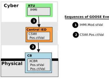
Control operations The remote operation of a circuit breaker is a basic
sub-station automation requirement. The breaker command, as demonstrated in Fig. 2.3, originates fromep an operator located at a HMI, represented by the IHMI LN [75]. The operator sends the command to the control IED, which is responsible for managing a circuit breaker’s control state with the CSWI LN. The control IED then updates its status, CSWI.Pos.ctlVal, to tell the circuit breaker to operate by updating the status of XCBR.Pos.ctlVal. After this has occurred, the breaker should update open and its current status, XCBR.Pos.stVal, should change to represent its new state.
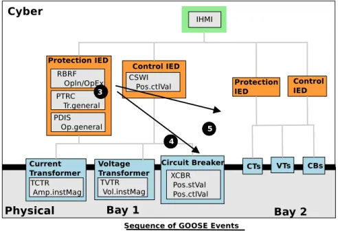
Protection scheme operation: Fig. 2.4 demonstrates how a protection scheme
operation can be enabled by IEC 61850 based on work demonstrated in [2]. As demon-strated in Fig.2.41a and 1b, a protection IED continually receives the current and voltage level from transformers. If the fault identification LN (e.g., PDIS) identifies a fault on the line , it will update its fault status signaling the operation of the protection trip con-troller, PTRC (2). When the protection trip control LN receives the fault identification (3), it updates its status and sends a message to the circuit breaker. Once the circuit breakers receives this command, it will trip to clear the fault and then update its status,
Figure 2.3 61850 control operation
XCBR.Pos.stVal (4).
Because most faults are transient, once the breaker trips and the fault clears, the breaker can be reclosed and the line can be re-energized. To enable the breaker reclosing, a reclosure LN (RREC) will be enabled when it receives the PTRC trip status (3). This initiates a timer in RRC which waits for the fault to clear. Once the timer expires, the reclosure IED updates its status to identify the breaker of the reclosing (5). Upon receiving this update, the circuit breaker will reclose and then update its status (6).
Breaker failure protection: Protection schemes must also incorporate methods to deal with failures of circuit breakers. Various circuit breaker failures can occur, such as a breaker not opening appropriately, or a breaker opening successfully, but not clearing the fault. Circuit breaker failure functions attempt to mitigate both situations by sending a breaker trip command to backup breakers which can then be tripped in order to clear a fault. A breaker failure operation is initiated as soon as a fault is discovered by a protection relay. Once this occurs, a timer is started to provide sufficient time so that the primary protection relays to clear the fault. If the fault has not been cleared in this time period, a command will be sent to operate backup circuit breakers.
Figure 2.5 61850 breaker failure operation
strated in [21] and [115]. Fig. 2.5 demonstrates the sequence of a breaker failure opera-tion. It begins similar to a normal protection function, except the added RBRF device is enabled by the PTRC status (3). Once the RBRF timer expires, it verifies that the breaker’s status has been updated to reflect the trip. If the fault has not been cleared, a retrip packet will be first sent to the primary circuit breaker (4). If this does not clear the fault, an external trip request is sent to the backup breakers with the RBRF.OpEx packets (5). Once this data has been sent, the backup breakers should operate to clear the fault.
2.2.2.3 Security concerns
Substations automation systems are critical to the reliability of the electric power grid, especially in the transmission and generation domains. Substation communications must also provide high performance. Many substation applications, such as protective relaying, which requires tripping breakers to protect physical equipment from spikes in
current, must be executed within milliseconds. Additionally, because substations are geographically dispersed and often maintain limited physical network protections, they are often very exposed to attackers.
An attack against a substation could have a major impact to the power grid. Research in [15] proposed methods to compute how cyber attacks against a substation could result in a loss of load. In addition, real-world situations have demonstrated that attacks to relays could cause instabilities to generators and the grid’s voltage [117].
2.2.3 WAMS
Increasing strain on bulk transmission, dynamic generation due to renewable energies, and increased sensing capability has instigated the development of WAMS to provide increased awareness of grid status. PMU’s provide high sampling rates and accurate GPS-based timing to provide highly accurate and synchronization of phasor readings. While the deployment of PMUs provide increasingly accurate readings, the full potential will not be realized unless these readings can be shard among utilities and regulators. Additionally, power system applications must be reviewed and redeveloped to determine the extent these granular readings may provide to both grid efficiency and reliability. The development of advanced control applications will depend on WAMS that will effectively distribute the information in a secure and reliable manner. Recently, the NASPInet initiative has focused on developing an architecture sufficient for a North American based WAMS deployment [20]. NASPInet has identified publisher/subscriber access control mechanisms to support the dynamic sharing of PMU data.
Unfortunately, the development of a WAMS presents numerous cyber security con-cerns [13]. The infrastructure must provide both high availability and integrity of the PMU data, while also providing some confidentiality of certain utility data. The develop-ment of such an architecture presents numerous constraints on the cyber infrastructure. The support for confidentiality and integrity will be primarily based on cryptographic
primitives specifically, asymmetric, public key cryptography. It must also provide sup-port for publisher/subscriber access control mechanisms and multi-cast communications.
2.2.3.1 Protocols
IEC 61850-90-5 WAMS deployments will depend on the availability of effective
standards to storing and communicating PMU measurements. While the IEC 61850 standard primarily focuses on the substation automation identified in Section 2.2.2, IEC 61850-90-5 is an emerging standard that will support the need to transmit PMU mea-surements across a network [67]. The standard expands upon the IEEE C37.118 standard which focuses on data storage formats to also provide support of both serial and IP-based multicast transmission. IEC 61850-90-5 maps PMU data formats into current IEC 61850 protocols to support communications with Phasor Data Concentrators (PDC) and other PMU devices.
2.2.3.2 Security concerns
The deployment of a WAMS presents numerous cyber security concerns [12]. The infrastructure must provide both high availability and integrity of the PMU data, while also providing some confidentiality of certain utility data. The infrastructure must si-multaneously send PMU readings to many different parties to ensure everyone has a real-time system view. Therefore, the infrastructure must utilize multicast traffic to conserve network bandwidth. The design of adequate access control and authentication is also challenging. Malicious individuals must not be able to spoof or modify PMU messages as this would result in inaccurate utility estimations of the grid’s state.
2.2.4 CIM
The smart grid presents an increased need for CIMs to provide a common format for expressing and communicating the information required to support the grid [73]. The
development of standard data models provide consistent data representation to help facil-itate improved interoperability, configuration, and management. Current CIM standards such as IEC 61968 and IEC 61970 present ontologies that formalize the information and its relationships. IEC 61790 presents a standard of the data objects necessary to sup-port the transmission system. Data classes for this model include loads, measurements, topologies, wires, generators, SCADA, and protection. Similar to IEC 61970, IEC 61968 provides an equivalent standard for the distribution systems. Core data classes for this model include assets, consumers, work flows, and documentation.
The models provide a standard for data objects which may be stored and transmitted in multiple different formats. Therefore, the use of CIMs also requires mappings to many other data formats used in the smart grid. For example, Section 2.2.2.1 introduces the data model used for the IEC 61850 protocol. Objects in this model can be mapped to those in IEC 61790 to provide an overarching view of data used in various domains and systems [42].
While CIMs have primarily been developed as a mechanisms to support grid inter-operability, they also present a key element to understanding the security requirements of the system by providing a mapping of data to the networks and systems that must protect it. This research leverages these properties as a key component in understanding impacts from cyber security failures.
2.3
Cyber threats to the smart grid
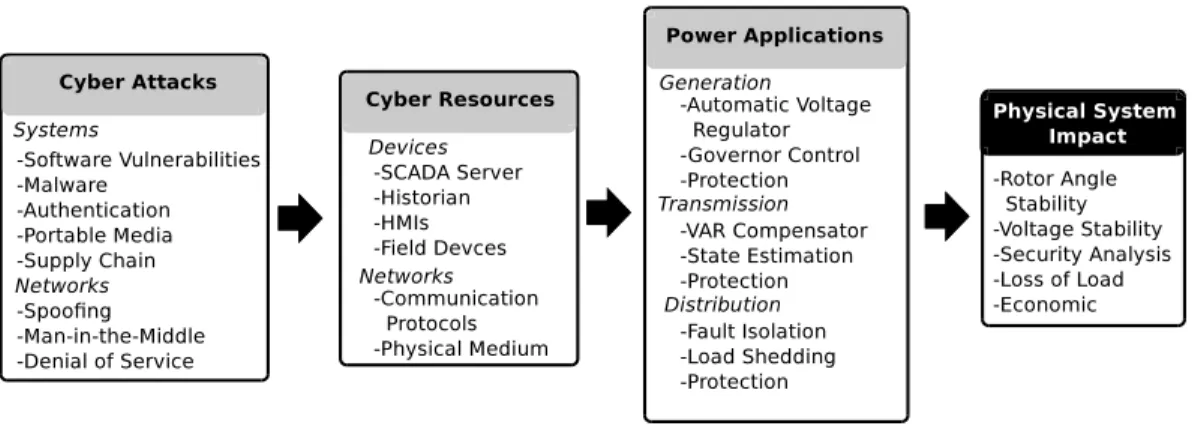
Attacks against the smart grid will likely differ from many traditional attacks against cyber environments. First, an attacker must be able to compromise the grid’s cyber elements. However, in order for the attack to cause negative system impact, the attacker must also know how to control the cyber elements in order to manipulate the physical system. Fig. 2.6 demonstrates this relationship.
Figure 2.6 Attacks to the smart grid
An attacker could potentially use a number of approaches to compromise the grid’s cyber resources. These resources will be the same set of devices and communications previously identified. By compromising some set of cyber resources, an attacker can then gain some degree of control over the various power applications. Depending on that set of compromised power applications, an attacker may then be able to cause physical system impact. Physical impacts could include grid instabilities, loss of load, and influencing market prices. Work in [94] more thoroughly explores the set of power applications used to support the various smart grid domains along with weaknesses in the supporting cyber infrastructure.
This section will introduce potential attacks which could impact the communications of smart grid, along with those that could compromise the sets of systems and devices.
2.3.1 Communications
As demonstrated in Table2.1, the smart grid depends on many different communica-tion flows which have varying importance and security requirements. If an attacker is able to manipulate these communications, they could control the computations performed by various connected systems which would then impact the physical grid. Potential attack against communications include the following items:
Spoofing - A spoofed message is one that an attacker injects into the network to make it appear as if it originates from a trusted system. While this is possible in both wired and wireless systems, the latter remain more vulnerable as the attacker can more easily access the physical medium. Spoofing is generally prevented by employing some form of cryptographic authentication which requires that the attacker sign or encrypt the spoofed message with a shared or private key in order to verify its integrity. However, the smart grid communications present numerous concerns, specifically because many protocols were designed with inadequate authentication [47]. Additionally, the high availability requirements and large number of devices present challenges when applying more secure approaches [38].
Denial of Service (DOS) - Networks are vulnerable to DoS attacks if an attacker is able to inject large number of packets into the network which cause congestion and limits the network’s availability to the intended functions. While both wired and wireless networks are vulnerable, wireless networks remain extremely vulnerable to DoS because the physical medium cannot be more easily accessed by an attacker. Additionally, DoS can also occur if a malicious packet causes the server to crash when attempting to process the packet.
Man-in-the-Middle (MitM) - The network is also vulnerable to many different
MitM attacks if the physical medium is not protected or the attacker can manipulate some network address (e.g., Address Resolution Protocol (ARP)) or routing mechanisms (e.g., Border Gateway Protocol (BGP)). If an attacker performs a MitM attack they would be able to manipulate the authentic communications in transit. Because the smart grid incorporates many new protocols for systems such as AMI, there are documented concerns about possible routing layer vulnerabilities which may enable DoS attacks [80].
Misconfigurations - Network misconfigurations also present serious vulnerabili-ties to communication networks. Configurations in devices such as firewalls focus on segmenting trusted and untrusted portions of a network. Therefore, a misconfiguration of these devices may result in an untrusted user gaining access to critical system com-ponents. Incorrect and insufficient network segregations have been identified as a core concern throughout the smart grid [80].
2.3.2 Systems and devices
In addition to the communication networks, the systems and devices used to control the grid are also vulnerable to attack. This section previously enumerated the common types of devices found within the smart grid. The remainder of this section will identify attacks against these systems.
Software vulnerabilities - Software vulnerabilities, such as buffer overflows, in-teger overflows, and structured query language (SQL) injection, can provide an attacker with the ability bypass authentication to usurp control of a system. Numerous recent studies have suggested software vulnerabilities significantly plague smart grid systems [47][24]. Additionally, control systems, such as the smart gird, are especially difficult to patch due to a need for high up-time. This constraint will likely leave systems extremely vulnerable to software vulnerabilities.
Authentication issues - Many devices within the smart grid do not use strong
methods to authenticate users. While devices are configured with default or weak pass-words, additionally, many system features often completely lack authentication support [114]. Authentication issues could provide unauthorized users with the ability to manip-ulate system settings and operations.
Malware - Malware is any malicious software which an attacker is able to execute on a target system in order to usurp its control. While malware is frequently used for data exfiltration in tradition ICT environments, malware which manipulates or denies control of a physical system will likely be more damaging against the smart grid. While researchers have proposed that malware could impact SCADA systems by injecting ma-licious control communications [37], Stuxnet introduced the first real-world instance of malware specifically infecting and performing nefarious actions within field devices [36].
Portable medial - Most smart grid devices are not directly connected to the un-trusted Internet. While this significantly increases the difficulty for an attacker to ac-cess the system, it does not provide complete security. A sophisticated attacker may be able to transfer malware into the system use some form of portable media. Stuxnet demonstrated that malware could infect air-gapped control systems by spreading through portable media [36].
Supply chain - A supply chain attack could include any attacker technique that compromises a system’s integrity before it is deployed. While attacking the supply chain requires high sophistication, recent reports suggest many foreign network devices may contain back-doors that provide access to unauthorized users [109]. Supply chain attacks are similar to portable media in that they do not require an attacker to have physical system access. Supply chain issues also incorporate the need for trusted system updates and patches which have been used in sophisticated cyber attacks [27].
CHAPTER 3.
CYBER ATTACK EXPOSURE
EVALUATION FRAMEWORK
3.1
Introduction
The coupling of the power infrastructure with complex computer networks substan-tially expand current cyber attack surface area and will require significant advances in cyber security capabilities. Strong security metrics are necessary to ensure security-based decisions accurately reflect a realistic understanding of cyber risk. NIST specifically ad-dresses this requirement and recommends research in “tools and techniques that provide quantitative notions of risks, that is, threats, vulnerabilities, and attack consequences for current and emerging power grid systems” [80].
Attack trees and graphs have previously been used to model network security, un-fortunately these models will not scale to large networks. While they provide detailed information on potential attack methods, their development is based on an understanding of potential attacker goals. Current trends show attackers increasingly rely on exploiting zero-day vulnerabilities [101], which reduces the accuracy of models depending on the evaluation of known vulnerabilities.
Developing security models for a large, networked environments such as the smart grid should focus on the critical information necessary to support the grid and the resulting se-curity mechanisms deployed to protect it. The electric grid can typically be categorized into d
![Figure 1.1 Power system domains[34]](https://thumb-us.123doks.com/thumbv2/123dok_us/441959.2551124/17.918.277.667.115.449/figure-power-system-domains.webp)