Construction and experiment on micro-gyroscope detection balance
loop
Wang Xiaolei
1,2,a *, Zhao Xiangyang
3, Cao Lingzhi
1, Liu Yucui
1, Zhang Jitao
11
College of Electric and Information Engineering, Zhengzhou University of Light Industry, Zhengzhou 450002, China;
2
Southeast University, Nanjing 210096, China;
3
Henan Mechanical and Electrical Engineering College, Xinxiang 453003, China
Keywords:micro-gyroscope; detection balance loop; Coriolis effect; closed-loop control
Abstract. In order to overcome the defect of open-loop detection of micro-gyroscope, based on comb capacitance detection of micro-structure, the working principle of electrostatic force suppressing capacitance comb vibration was analyzed. The Coriolis signal vibration amplitude of micro-gyroscope was extracted; with the Coriolis vibration amplitude as the control variable, the detection balance loop of micro-gyroscope was constructed. The experimental result shows that the constructed detection balance loop is able to balance the Coriolis force and suppress the Coriolis vibration. The scale factor linearity and symmetry have greatly enhanced, and the measurement range, the threshold and resolution have improved at some extent.
Introduction
Micro-gyroscope is a MEMS (Micro-Electro-Mechanical-System) inertial sensor to measure the angle rate of the rotating body. Because of the small volume, light mass, low power and low cost, the micro-gyroscope is widely used in automobile attitude control, robot autonomous navigation, optical image stable platform and other fields[1].
Micro-gyroscope is composed by drive mode and detection mode. Drive mode is the prerequisites of the micro-gyroscope working normally, whose vibrating frequency and amplitude are controlled at the closed-loop mode[2]. In detection mode the Coriolis vibration most use the direct demodulation at the open loop, which is simple and easy to realize. However, micro-gyroscope may work at the extreme condition, such as strong vibration and shock, and the external disturbance enters into the detection mode, which introduces the error, even leads to system working abnormally.
In order to overcome the defect of open loop detection, some experts start to explore the closed-loop detection method. Y. Dong[3] presents a novel 6th order continuous-time, force-feedback band-pass sigma-delta modulator control system for the detection mode of micromachined vibratory gyroscopes. S. Sung[4] investigates a new loop design approach of force balance control for the vibratory rate sensor, which takes advantages of the modified automatic gain control configuration in controlling the system’s oscillating dynamics. B. Eminoglu[5] introduced a new baseband equivalent model for sense mode dynamics of a MEMS gyroscope providing a more accurate force-feedback controller design. J. Cui[6] presents a design method of force rebalance control for the sense mode of a micro-machined vibratory gyroscope, which is based on constraining sensitivity margin specifications via numerical optimization approach. But most of these research stay in theoretical stage.
In this article, a novel detection balance loop of micro-gyroscope is constructed and designed, which utilizes external force to balance the Coriolis force at the detection direction, and make the vibrating mass tend to equilibrium state. Experimental result shows that the linearity, symmetry, measurement range and other performance of micro-gyroscope has greatly improved.
Micro-gyroscope detection and balance loop
Line vibratory micro-machined gyroscope adopts capacity coupling to drive and detect mass vibration, a simplified microstructure schematic of doubly decoupled micro-gyroscope is showed in Fig. 1. There are two groups of combs in the drive mode, slide-film drive combs and drive-sense combs, which constitute a closed-loop control system. Here, in order to implement the closed-loop control in detection mode, a group of balance comb is added to suppress the Coriolis vibration. If imposing voltage on the balance combs, the electrical energy forms between the fixed combs and movable ones, and a tangential force generates at the detection direction, which acts on the mass to balance the Coriolis force.
mass balance
comb
detection comb
drive comb drive-sense comb
y x z drive comb detection comb movable fixed
Fig. 1 Simplified microstructure schematic of doubly decoupled micro-gyroscope
In the balance comb microstructure, the comb gap is x0, the overlapping length between fixed
comb and movable comb is y0, and the comb thick is z0. As an example on the left side of the
microstructure, when the up and down comb applied the voltage are Vd + Vacos(ωdt) and Vd - Vacos(ωdt), the tangential electrostatic force is caused by the electrical energy in the y axis is
( )
0 0 4 cos y yu yd d a d z F F F V V t x ε ω = + = . (1) Where, ε is the dielectric constant of the comb capacity.Therefore, when the frequency and phase of electrostatic force are identical with that of the Coriolis force, the electrostatic force size can be regulated through changing the external voltage Vd and Va value, until the Coriolis force is balanced and the Coriolis vibration is suppressed.
Construction on micro-gyroscope detection balance loop Coriolis amplitude extraction
According to the Coriolis Effect principle, when there is an input angle rate Ωz along z axis, vibration velocity in x axis will couple to y axis direction and the Coriolis force fc generates. Assume the vibration displacement x is Axsin(ωdt), Ax and ωd are the vibration amplitude and vibration frequency respectively, then the Coriolis force is
( )
2 2 cos
c c z c z x d d
f = − mΩ = −x& mΩ Aω ω t . (2) Where, mc is the Coriolis mass, which is the effective mass of the mass block. The negative sign represents the direction of Coriolis force is opposite to the y axis positive direction.
When the Coriolis force acts on the mass of micro-structure, there is vibration displacement output in y axis direction. After displacement-capacitance to voltage conversion, the voltage signal which reflects y axis comb vibration is obtained. The weak voltage is amplified, regulated and demodulated, and the Coriolis vibration amplitude can be extracted. The detailed process is shown in Fig. 2.
Fig. 2 Coriolis amplitude extraction Where
( )
(
)
2 2 1 y s y y y m G s s ω Q s ω =+ + is the transfer function in detection mode, my is the effective
mass in detection direction, Qy is quality factor in detection mode, kin is the interface gain, Lf(s) is low pass filter.
Micro-gyroscope output represents
( )
cos(
)
c y d y s t = A ω t+ϕ . (3) Where(
2 2)
2 2 2 2 2 c z x d y y d y y d y m A m A Q ω ω ω ω ω Ω = − +is the vibration amplitude,
(
2 2)
arctan d y y y d y Q ω ω ϕ ω ω = − − is the detection phase.The output after demodulation is
( )
(
)
( )
(
)
(
)
cos cos 1 cos 2 cos 2 c in y d y d in y d y y y t k A t t k A t ω ϕ ω ω ϕ ϕ = + = + + . (4) Through low pass filter and filter out the high frequency component, the demodulation signal becomes( )
1 cos 2 c in y y r t = k A ϕ . (5) Where rc(t) is the Coriolis signal corresponding to the input angular rate.Balance loop construction
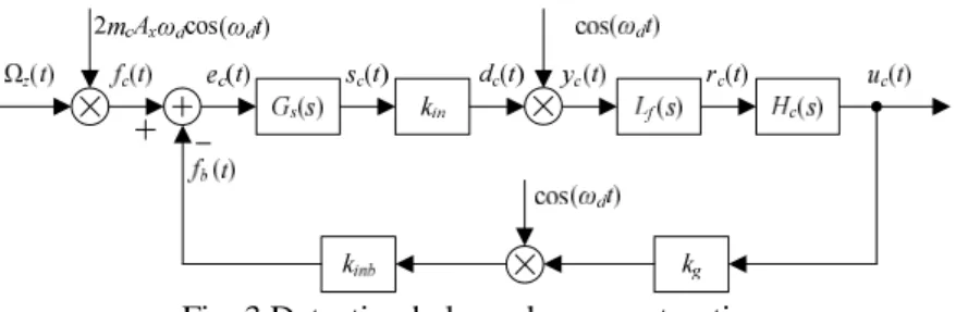
On the basis of the open loop solving the Coriolis signal principle, the Coriolis signal is seen as the control variable for the balance comb to suppress the Coriolis vibration. The whole balance loop is constructed, shown as the in Fig. 3.
Fig. 3 Detection balance loop construction
Where, Hc(s) is the control law for correcting and optimizing the performance index of control loop. kg is the external gain, which amplifies the control signal to the appropriate range. kinb is the interface gain of balance force, which is related to detection interface micro-structure. uc(t) is output function, which is not only the control signal for stopping the Coriolis vibration but also in proportion to input angular rate.
The feedback balance force is
( ) ( )
cos( )
b inb g d
f t =u t k k ω t . (6) The error function is
( )
( )
( )
c c b
e t = f t − f t . (7) In order to reduce the error and improve the stability, a lag correction segment is connected at the function rc(t). The lag corrector contains proportional and integral function, which has good performance of increasing the open-loop amplifier gain, reducing the system error and improving system stability. However, the introduction of lag segment confines the bandwidth of closed-loop
system. In order to expand the closed-loop system bandwidth and improve the system dynamic performance, it is necessary to cascade the lead correction segment. So, the control law Hc(s) adopts lead-lag correction, whose transfer function is
( )
1 3 2 4 1 1 1 1 c p T s T s H s K T s T s + + = + + . (8) Where Kp is gain coefficient; T1, T2, T3 and T4 are correction parameters, in addition, T2 > T1 > T3 >T4. By adjusting the correction parameters, the closed-loop system can meet the performance
requirements for stability margin and bandwidth.
Experiment and analysis
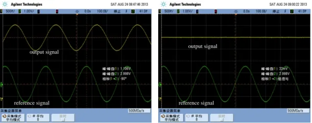
According to the scheme proposed by the above, a micro-gyroscope detection balance circuit is designed, the corresponding PCB board is manufactured, and the vacuum sealed micro-gyroscope is mounted on the PCB. Place the micro-gyroscope on a single axis rate turntable and test the main performance. Fig. 4 is the uc(t) output comparison between open loop and closed loop mode.
a) open loop output b) balance closed loop output Fig. 4 Output comparison between open loop and closed loop
The partial test data comparison between open loop and balance closed loop is shown as table 1.
Table 1 Partial test data comparison of open loop and balance closed loop Test item Open loop Balance closed loop Non-linearity of scale factor (ppm) 516 87.3 Asymmetry of scale factor (ppm) 595 43.1 Measurement range (º/s) ±200 ±300 Threshold value (º/s) 0.005 0.003 Resolution (º/s) 0.005 0.004
Therefore, we can summarize that balance closed loop detection technique, compared with the open loop detection, makes mass vibrating near the equilibrium position, which is beneficial to suppress the external disturbance. The scale factor has a great improvement, linearity increases 5 times and symmetry increases 13 times; Measurement range, threshold value, resolution and other performance have different degrees of improvement.
conclusions
In this article, the principle of micro-gyroscope detection balance mechanism is analyzed, which is used to suppress the Coriolis vibration, the micro-gyroscope detection balance loop model is constructed, and the detection balance loop is designed. The experiment result shows the detection balance loop can effectively suppress the Coriolis vibration, improve the linearity and symmetry of scale factor, expand the measurement range, and improve threshold value and resolution and other performance.
reference signal reference signal
output signal output signal
Acknowledgements:
This work was supported by Doctor Research Funded Projects of ZZULI (2014BSJJ046), and I expressed my thanks for this.
References
[1] D. K. Shaeffer, MEMS inertial sensors: A tutorial overview, Communications Magazine, IEEE. 51(2013) 100-109.
[2] Xiaolei Wang, Hongsheng Li, Bo Yang, Design and implementation of digital closed-loop drive control system of a MEMS gyroscope, Journal of Southeast University(English Edition). 28 (2012) 35-40.
[3] Y. Dong, M. Kraft, N. Hedenstierna, et al, Microgyroscope control system using a high-order band-pass continuous-time sigma-delta modulator, Sensors and Actuators A: Physical. 145 (2008) 299-305.
[4] S. Sung, S. Yun, W. T. Sung, et al, A novel control loop design and its application to the force balance of vibratory rate sensor, International Journal of Control, Automation and Systems. 7 (2009) 545-552.
[5] B. Eminoglu, S. E. Alper, T. A. Akin, A new baseband equivalent model for sense mode dynamics and its effects on force-feedback controller design for mems gyroscopes, IEEE Sensors. (2011) 157-160.
[6] J. Cui, Z. Guo, Q. Zhao, et al, Force rebalance controller synthesis for a micromachined vibratory gyroscope based on sensitivity margin specifications, Journal of Microelectromechanical Systems. 20 (2011) 1382-1394.