’94-‘95 Mustang GT 5.0 HO Smog System Removal
This is a ‘How To’ article to remove the smog system from a ’94-’95 SN95 5.0 HO Mustang GT and installing a delete pulley kit in its place. I tried to include everything as best as possible but take note that some of the elements may not be outlined. Use this article at your own risk. Consult your local laws regarding emissions prior to proceeding with this project. Should you require any further information in regards to this ‘How To’ see my contact info at the end of the article and I will help to the best of my knowledge.
Things You Will Need:
o Assortment of Metric and Standard Tools the more you have the easier it will be. o 2 - 9/16”x1” NC GR5 bolts.
o 6 - Washers for the above bolts o Delete Pulley Kit
o 2 – screws or bolts to plug vacuum lines o Penetrating Spray
o Loc-Tite (Blue stuff – you may need to reverse this someday)
o Hammer, screwdrivers, needle nose, vise grips, utility knife, rags…..all the basics. o Grinder or File
o Coolant
o Heater Hoses (if you can’ t get the old ones off without cutting them) o Gloves & Safety Glasses
o Electrical tape o Jack & Jack Stands o Drain Pan
o A second car – not necessary but good to have incase you need something. Thank you winter beater.
1. Disconnect negative battery terminal. 2. Remove the strut tower brace if applicable
3. Locate all the bolts you will be removing and spray with penetrating oil. I advise spraying the bolts located at the back of each head a day in advance. See Figures 4 & 5.
Figure 1. This is the best penetrating spray I’ve tried to date. Don’t drink & Drive!
Tip: Get some jars or containers with lids to put all the removed bolts into to prevent losing one. I like glass jars so I can see what is in it at a glance.
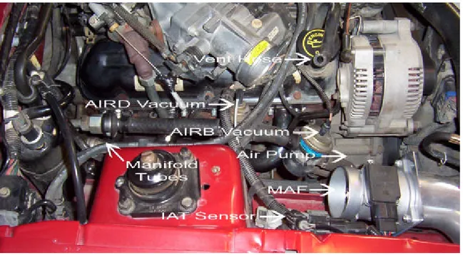
4. Remove the air inlet tube from the MAF to the Throttle Body or whatever CAI you have in order to get to the smog components. See Figure 2.
Tip: Mark all connections removed in order to prevent forgetting to reconnect one and end up chasing some simple problem for a week. I tie a piece of survey tape around each one and remove the tape only after reconnection is complete.
Figure 2. Air inlet tube removed. Unplug the Vent hose and IAT sensor from the inlet tube and loosen the clamps at either end and remove the inlet tube. You can now clearly see the AIRB (Bypass) and AIRD (Diverter) valves and most of the associated hoses that will be removed.
5. Unplug the AIRD and AIRB va lve vacuum lines then loosen the clamps at the back of the smog system where the hoses connect to the manifold tubes. Also loosen the clamp on the backside of the AIRB valve and remove the AIRD valve and connected hoses as an assembly. See Figure 3
FYI: One manifold tube runs around the back of the block and injects air into the back of each cylinder head and the other runs under the car to the passenger side of the exhaust.
6. Loosen the clamp at the air pump that connects the hose from the AIRB valve to the air pump. Remove the AIRB valve assembly. See Figure 3.
7. Remove the bolt from the back of the Alternator that holds the bracket which supports the AIRB valve. Remove bracket. Tape bolt to the bracket or put bolt back into the alternator to prevent losing it.
Figure 3. Shows location of all clamps and connections to loosen to remove system. Remove the AIRD portion first which will allow access to the clamp on the air pump where the AIRB valve hose connects.
8. Next I turned my attention to the manifold tube that wraps around the back of the block. It is held on by two bolts. One into the back of each head, which require a ½” wrench or socket. The hardest part here, assuming you sprayed the bolts with pene tration oil earlier, is getting the wrench/sockets on the bolts and still having leverage. For the drives side I just moved the A/C lines and other vacuum lines out of the way the best I could and managed to pull it off. I have large hands so if I can get at this stuff just about anyone can. I figured this would be the hard side but its not. See Figure 4.
Figure 4. Shows the drivers side location of manifold tube bolt to be removed. It’s a lot easier to get to than it looks.
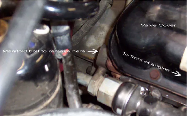
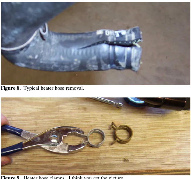
9. Next remove the manifold bolt on the passenger side from the back of the head. I tried to get this bolt out without removing the heater hoses but in the end….by by hoses. See Figure 5, 6, 7, 8 & 9.
10. Before removing the heater hoses drain the coolant so the level in the radiator is below that of the hoses. The petcock for draining the radiator is located on the passenger side of the radiator. My coolant was due for a change so I just drained the entire system. I was going to try to save the hoses and just reinstall them but I just couldn’t get them free from the lines that run along the lower intake manifold. So I just cut them off with a utility knife.
Caution: Do not use a screw driver or other object to try to pry the hoses off. This will damage the soft steel lines to which they mount and will most likely leave you with a leaky system. They are fairly inexpensive so just get new ones. For these hoses I had to go directly to ford as other local parts suppliers didn’t carry them.
Figure 5. Shows the passenger side location of manifold tube bolt to be removed. This looks to be the easy side but it wasn’t.
Figure 6. Shows the heater hoses to be removed.
Figure 7. Shows the heater hoses removed. You can see the mark the knife left when I cut the top hoses off. This shows how soft and easily damaged the steel lines are. There was some rust on the lines at the back of the manifold. Use some emory cloth to clean up the connection prior to reinstalling hoses.
Figure 8. Typical heater hose removal.
Figure 9. Heater hose clamps. I think you get the picture.
11. Now I was able to get to the passenger side bolt with a little more ease. All that work and this is what you get. See Figure 10.
12. To get the tube out that runs under the car to the exhaust pipe will require some cutting and welding to plug the hole which an exhaust shop should do for around $10.00 cash. You can drive the car with this tube on and nothing connected to it. It has a one way check valve, just like the manifold tube in Figure 10, which will prevent exhaust from coming up and out the tube into the engine compartment. If you have a welder and the room to get under your car, go for it. Fortunately for me, I had a custom x-pipe put on last fall and the shop just plugged the line and tacked it to the pipe so I just busted it off.
13. Now I started on the air pump. Start by removing the serpentine belt. Next, to make removing the pump easier, remove the alternator. Now in order to remove the air pump you must take the pumps pulley off to get the top bolt out. This is simply achieved by removing the three bolts on the front of the pump which use an 8mm wrench. See Figure 11.
Figure 11. Remove the three bolts shown to remove pulley.
14. Now remove the 2 bolts holding the pump in. The air pump will have to be removed from the underside of the car. Now the entire smog system is out. See Figure 12.
Figure 12. Here it is. You can see how my tube that goes to the exhaust under the car was already cut off, crimped and welded shut. I just had to break the tack weld that held it to the exhaust. Normally this would need to be cut off and the hole in the exhaust welded shut.
15. The next thing is to plug the holes in the back of the heads where the manifold tube once injected the air. A bolt will only thread in approximately ¾” but standard bolts only come as short as 1”. So cut them off or use washers as I did (need three on each side). My heads required a 9/16” NC (coarse thread) bolt. 9/16” is the bolts size not the bolts head size. See Figure 13.
Figure 14. Showing the washers taped onto the bolt for ease of installation.
17. Now I plugged the AIRD and AIRB valve vacuum lines. I found a small bolt in my shop close to what I needed and headed off to the bolt store again. The two vacuum lines are different sizes and one requires a smaller bolt than the other. Bolts and screw are like 15-30 cents each in bulk so I just picked up a bunch of different ones and tried them all until I found a best fit. See Figure 15.
18. With the heads and vacuum lines now plugged you can install the heater hoses and refill the coolant to the proper level. The outside firewall mount connects to the lower tube on the intake manifold and the inside firewall mount connects to the upper tube on the intake manifold. Remember to have the clamp on the steel line or over the hose itself prior to pushing the hose into place. Use a vise grip to hold the clamp open until you get the hose positioned and release the vise grip. See Figure 16.
Figure 15. Showing the vacuum lines plugged. The bolts or screws should be large enough to require a screwdriver to turn them in, this will ensure a positive seal.
Tip: Dip the ends to the new heater hoses in new coolant to ease the installation. This will provide a lubricant to slide the hose on easier and slide the clamps over the hoses easier.
Figure 16. Use a vise grip so you don’t have to try to hold the clamps open. These clamps require quite a bit of force to hold open.
19. Now take some electrical tape and tuck the vacuum lines away and tape them securely into place away from any heat. I left the plug bolt/screw exposed should I need to get at them for some unforeseen reason.
20. Next put the delete pulley on. The pulley used here is from ASP (Auto Specialties Performance). First test fit the pulley. I found that a corner of the mounting block interfered with the OEM mounting bracket and a little talking to with the side grinder fixed things nicely. See Figure 17.
Figure 17. Showing the removed corner from mounting block. I used a side grinder but this could be accomplished with a file as well.
21. Once you have removed enough material to prevent any binding install the pulley assembly and torque the bolts.
22. Put the alternator back in and reconnect the wiring and reinstall the serpentine belt.
23. Reinstall the air inlet tube from the MAF to the Throttle Body or whatever CAI you may have.
24. Do a final check over the entire engine compartment to make sure you have reconnected any and all sensors, lines, hoses & belts. Check for tools or anything else lying around the engine.
25. Reconnect the negative battery terminal and start the car. Take the car for a short trip and return. Check to see if the delete pulley is causing any exponential wear on the belt.
Summary:
The bang for your buck on this UNinstallation can’t really be considered here. You do a lot of work for what seems like nothing but I’m very happy I did it.
They say this procedure doesn’t produce any real power gains, but I did notice how my engine seems to turn a bit more effortlessly now, and it took care of that annoying air pump sound. This is also the beginning of a diet for the front end of my stang. I did this entire project without lifting the car off the ground except for removing the manifold tube that runs under the car. Whenever going under a car be sure it is properly supported with jack stands and block the tires still on the ground.
This is only one of the possibilities for removing the smog system. There are several possibilities from removing the entire system or just some of the components but I feel this UNinstallation is by far one of the cleanest methods.
I would recommend this project just for the simple fact that you can learn a lot about the basics of how some of systems work within the engine compartment and it also provides a chance to thoroughly go over a lot of the mechanical systems in the car.
If you require any further information in regards to smog system removal my email is sbschwartz@hotmail.com or look me up on allfordmustangs.com. I’m under the user name Flintstone.
Edit: Now that I have driven the car a fair amount after the UNinstallation I’ve noticed how my exhaust tone changed as well. The o/r x-pipe used to pop on deceleration but no longer does. It also lowered the tone a fair amount and the growel is quite a bit more aggressive. Just another bonus to the project.
DILUTION IS NOT THE SOLUTION TO POLLUTION…EFFICIENT ENGINES ARE Future ‘How Tos’ – Air Condition Removal
- Battery to Truck Relocate
Glossary:
MAF – Mass Air Flow Sensor
IAT – Intake Air Temperature Sensor
AIRB – AIR Injection Bypass Valve
AIRD – AIR Injection Diverter Valve
CAI – Cold Air Intake
ALT – Alternator