ARCHITECTURE ANALYSIS OF A THREE-DIMENSIONAL
HIGHWAY REAL-TIME SYSTEM
Xinsha Fu1, Haifeng Li1, Juan Zhu2 and Xuejun Xu1
1
College of Traffic and Communications, South China University of Technology 2
College of Computer Science & Engineering, South China University of Technology Guangzhou 510641, Guangdong, China
ABSTRACT
With the rapid development of freeway construction in China and the increasing demand for the improvement of the landscape and for safety in the highway system, the traditional method of the highway alignment design can no longer meet these needs. A new method, the three-dimensional highway real-time system (3DHRTS), is being developed to simulate the scene of the highway system, which has many advantages with regard to highway alignment, landscape and safety design by means of fly-through and interactions with the virtual scene. By analysing the disadvantages of the widely used current design method, the required performance and expansible architecture of 3DHRTS has been developed. The functions of the modules and the relationship between them, which determine the system action, is analysed in detail based on the architecture. In addition, the idea of object orientation and UML as a method are used to analyse, design and realise the system in the abstract as well as the relationship between the classes, including the terrain, the highway and how the data should be logically organised. Finally, data on the Guang-Wu expressway from Shanwei in Guangdong province to Qingshui in Yunnan province are used to test the 3DHRTS method, which is a prototype system whose main function is the three-dimensional rendering of the highway scene, such as the terrain, road and vegetation.
1. INTRODUCTION
With the rapid development of road construction in China, the concept of “safety, environmental protection, comfort and harmony” is regarded as the aim of highway design and construction. In fact, traditional highway design methods can no longer meet the increasing requirements regarding landscaping, road alignment and safety. As a result, as an improved method, three-dimensional visualisation is being increasingly used to aid in design, and to display and evaluate the design results.
The traditional highway design method is to use two dimensions (mainly including the horizontal, vertical and cross-section) to simulate three-dimensional information, which has reasonably simplified highway geometry design in past years (Fu Xinsha and Gong Dejun, 1998). However, due to this simplification, three-dimensional information cannot be presented, resulting in the non-availability of information on harmony between highway and environment, and the inability to make an objective evaluation of the relationship between road alignment and safety. It is believed that the traditional method leads to a disadvantage in evaluating the highway landscape, alignment and safety, which will eventually have an unfavourable effect on future highway construction with regard to the environment, the economy and society (Fu Xinsha and Gong Dejun, 1998).
In China, many studies have been done in the field of highway three-dimensional simulation (Cao Zhenyu and Qi Hua, 2004; Chen Dongsheng, 2004; Zhao Jianjun et al., 2005). Basically, the order of work used in these studies is: first, the highway meshes are created based on the design data using road CAD software, generally on an AutoCAD platform; second, other models are generated, including the terrain, the vegetation, and the highway accessories; third, all of these models are integrated by means of the 3D modelling software, such as 3dMax, Maya and Blender; and finally, after a long time of non-real-time rendering, the video files are produced for the purpose of evaluating the landscape and road alignment. This type of method is called "static 3D visualisation" – it is able to render the highway and scene in a realistic way but still has some limitations as follows:
> Limited angle of view – Dynamic, arbitrary and interactive fly-through is impossible since scanning can only be done along a pre-scheduled track.
> Inability to expand and limited support functions – All the functions and paths have to be scheduled beforehand. Moreover, expanding more functions based on the original one not only requires re-starting all over again but also is time-consuming.
> Lack of an interactive function – Consequently, it is impossible to obtain any additional information, except pre-requested information.
> Low efficiency in aiding design. – Setting up this kind of animation often takes a lot of time. Any modification to the design means one has to start all over again. In general, the rendering of a real-time scene only takes a few minutes, while 3DMax or another program takes a few days or even longer.
With the development of computer and Cg technology, it is feasible to build a real-time system that allows for free fly-through and for dynamic interactive queries about any information the users want in order to improve design quality. The aim of the three-dimensional highway real-time system (3DHRTS) is to integrate the highway model made up of horizontal, vertical and cross-section information with the models of the terrain, the vegetation and the accessories around the highway to form a virtual environment, enabling designers to figure out the defects in the design. The development of 3DHRTS will therefore actively improve the level of design and the quality of evaluation in highway construction (Gamma, 2000). This paper focuses on the analysis of the system architecture and the functions, as well as the system modelling, the hierarchy and the inherent relationship between classes provided by the object-oriented method. The paper therefore does not cover the system realisation and mathematics.
2. THE ARCHITECTURE OF 3DHRTS
2.1 Objective of the System
Based on the Digital Terrain Model (Lee and Schachter, 1980; Shewchuk, 1996; Li Zhilin and Zhu Qing, 2003; Liu Xue Jun and Fu Xin Sha, 2001), and Road CAD (Fu Xinsha and Gong Dejun, 1998), 3DHRTS allows for fly-through and queries about ground attributes and attributes of road design, offering dynamic design results in 3D with a view to appraising the quality of the design and the harmony between the road and the environment. This system can be integrated with digital photogrammetry on the data level to render a virtual after-construction landscape. Simulated driving in this environment allows objective experience of the quality of the alignment, the landscape along the road and the harmony with the previous ones. With the geological database set up, and with the aid of 3DHRTS, it is easy to select a geological alignment.
3DHRTS can manage various complex data sets; this makes it superior to the digital terrain model system that can only handle terrain but cannot display objects such as bridges,
roads and vegetation. As a result, it can display the specific structural attributes of roads, bridges and accessories. In addition, since it is a physical simulation system, 3DHRTS can exactly reproduce road accidents and assess the quality of the alignment design in terms of safety.
2.2 System Construction Design
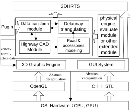
The well-designed architecture is the basis of a flexible, extendable and maintainable system. According to the principle of structured frames, the system has been designed with the following hierarchies:
> Hardware and operating system (regarded as a virtual machine) to control the hardware operation, process management, memory management and I/O attempter.
> The graphic API and foundation class library layer uses mainly OpenGL, the industrial standard in the field of computer graphics API, and C++ Standard Library, which is a foundation library including containers, iterators, function objects and algorithms in standard C++. It serves as a bridge between the application and the OS or Hal.
> 3D graphic engine and GUI layer. The 3D graphic engine is written in standard C++ and OpenGL, the core module for the 3D rendering, for managing the objects in the scene, the textures, the normal and graphic primitives, and for controlling the data flow between the CPU and the GPU. GUI, an interactive system between the user and the OS, captures the user’s commands and transforms them into system messages to activate different functions.
> The application layer is the core module for data acquisition, transformation and handling. It consists of data transformation between all the different kinds of file format, the modelling in 3D for the road, the terrain, the buildings and so on, the evaluation system for the relationship between the highway alignment and safety aspects, and the physical engine for the drive emulator. The 3DHRTS construction is shown in Figure 1 (the hollow arrows denote the hierarchy of each module, and the solid arrows denote the communication between the data).
3D Graphic Engine
OpenGL C++ STL
3DHRTS
GUI System
OS, Hardware(CPU, GPU) Highway CAD Module Delaunay triangulating Data transform module Road & accessories modeling vertex, norml, texture data physical engine, evaluate module or other extended module Abstract, encapsulation Abstract, encapsulation PugIn
3. SYSTEM FUNCTION DESIGN
3.1 Analysis of system function
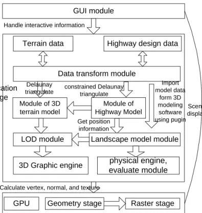
According to the design of the system architecture mentioned above, the function of 3DHRTS is categorised as follows: GUI module, the data transforming module, the module for the 3D terrain model, the highway model module, the landscape model module, the level of detail (LOD) module, the module of the 3D graphic engine and the physical engineering module.
Terrain data
Module of 3D terrain model
Highway design data
Module of Highway Model
Landscape model module
Delaunay triangulate Get position information constrained Delaunay triangulate LOD module Application stage Geometry stage
GPU Raster stage
Calculate vertex, normal, and texture
GUI module
3D Graphic engine
Data transform module
Import model data form 3D modeling software using pugin Handle interactive information
Scene display
physical engine, evaluate module
Figure 2. System construction of modules.
The GUI module includes the functions of data display and interaction with the user. Through the GUI module, fly-through can be achieved. In addition, the information concerned is available through interaction with the user who can, for example, obtain the geological attributes of the terrain, with support from the database, when picking up a terrain object on the screen.
The data transforming module. It is through data transformation that 3DHRTS can be integrated with other systems and that expansion of functions can be also accomplished. (See details in Figure 3.) Data transforming mainly includes:
Reading, refining and transforming of terrain data. Terrain data can be obtained by means of outdoor surveys, digitalisation of terrain maps and photogrammetry, and so on. These data need to be distilled to obtain useful information and eliminate "noise" data, sampling in line with the requirements and the required precision, and transforming the data into a format recognised by 3DHRTS because of the differences in data formats.
Reading and recognition of data of Road CAD software. The 3D model is built on the data on the horizontal, vertical and cross-section details of the highway available through this interface. However, these data also contain a lot of potential spatial data, including the highway reserve boundary lines, the median strip, the guardrails, the vegetation and the street lights. With these spatial data available, the model can be built automatically.
Importing the static model from the 3D model software. Importing the completed model from the 3D model software with strong functions can expand the compatibility and expandability of the system.
Module of the 3D terrain model. The system is mainly based on triangulation irregular net (TIN) (Liu Xue Jun and Fu Xin Sha, 2001; Voronoi, 1988). Empirical evidence shows that simulating the terrain surface by means of triangles as the basis can satisfy the project’s practical requirements. In this case, the system includes Delaunay triangulating from discrete terrain points and constrained Delaunay triangulating (CDT) with the data on the highway reserve boundary line as the constrained region.
Module of highway model. The highway 3D model is created from data on the horizontal, vertical and cross-section details of a highway. A highway network can be well described by means of departing integration. The highway is abstracted as a collection of segments (i.e. sections of the highway) and nodes (i.e. the connections between the segments, such as an intersection or a bridge). The segments and nodes are linked by fitting their cross-sections together, like the teeth of two gears. The highway network can be well described in this way. The constrained Delaunay triangulating method is also used to implement a seamless join between the highway and the terrain together (Lee and Schachter, 1980; Song Zhanfeng et al., 2003; Tan Kim Heok and Daman, 2004).
Module of landscape model. This includes the modelling of highway accessories, i.e. objects of simple structure that are either continuous or regularly distributed, such as vegetation, anti-crash guardrails, wave-shaped guardrails and street lights, and the modeling of other objects. These other objects, such as buildings and bridges, are relatively complex and are randomly distributed. Consequently, the model is created in 3D model software in the form of files read by the users by means of interaction and imported into the scene.
The level of detail (LOD) module (Tan Kim Heok and Daman, 2004). In order to meet real-time needs, it is necessary to adopt LOD technology to simplify a huge mass of terrain data and object data because of the length of the highway. Continuous view-dependent LOD is adopted to deal with terrain data and discrete LOD is applied to respectively deal with every object model.
Module of the 3D graphic engine (Eberly, 2001). The 3D engine can solve such problems as scene construction, dealing with objects, scene rendering and collision detection. It decides on the efficiency and reality of the rendering of a scene, so it acts as an engine to bind together all the elements of the scene and then command them to make a simultaneous, rendering channel. While the scene is being rendered, one of the most important sub-modules deals with lighting, texture mapping and so on. It can therefore be concluded that the quality of the graphic rendering module depends on the performance of
the 3D graphic engine.
Physics engine module. This module is responsible for modelling the dynamic behaviour of vehicles and vehicle collisions. Through this module, with reference to the data obtained from quantifying the performance and path of a vehicle, a check is made of the highway design parameters, providing the basis for assessing the coherence between driving safety and road alignment.
3.2 Object-oriented system design
The system uses object-oriented design. The difficulty resides in the decomposition of the system into object connections as the many elements concerned, such as encapsulation, granulation, dependency, relationships, flexibility, evolvement and results, affect the decomposition of the system and may conflict with each other. A complete system requires the definition of classes with clear structures and the design of effective co-operative relationships between these classes to reflect the process of development of the software, placing emphasis on improving the system structure. Visual modelling is done on the relationship between system classes through UML, effectively abstracting the structure of the whole system.
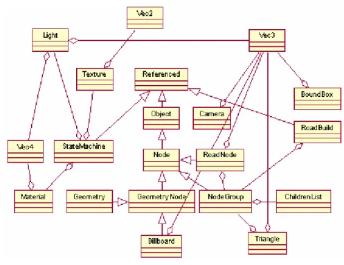
Based on experience with object-oriented design ideas and patterns (Gamma, 2000), the main class drawings defined by the system are shown in Figure 4. These classes are: ¾ Reference Class The base class used as a reference.
¾ Object Class The base class for object copying; requests I/O.
¾ Bound Box Class Calculates and saves the bound box information that is used for collision detection through a rectangle or circle.
¾ State Machine Class Encapsulates the OpenGL state machine.
¾ Node Class The base class for the object in the scene, based on a logic group divided and abstracted (Eberly, 2001).
¾ Node Group Class This class controls the object that can be grouped as a whole, or it can take a similar or relational action. It is a logic partition that can improve the efficiency of the real-time rendering (Eberly, 2001).
¾ Geometry Node Class This denotes the leaf node in a scene graphic that is real objects with a group of vertices, texture and normal data.
¾ Camera Class This describes the camera actions and attributes.
¾ Billboard Class This is a way of rendering based on images; it is responsible for the rendering of trees in a scene and is an effective way of displaying a great many trees. ¾ Triangle Class This contains the discrete points of the Delaunay triangle and renders
the terrain.
¾ Road Node Class The road node models the highway as a kind of node, as mentioned above.
¾ Road Build Class This class manages the highway design data and organises them logically to display the highway in the scene.
¾ LOD (level of detail) Class: It includes two types of simplifying model: one is the continuous view-dependent LOD used for terrain and the other is the discrete LOD involved in the case of single models such as bridges, trees, buildings, rendering a difference, resolving or even not rendering at all.
Figure 4. The relationship between the main classes of the system. 4. BUILDING AND TESTING OF THE SYSTEM
4.1 System development and run-time environment
3DHRTS was developed on the basis of the results of the system architecture and analysis of functions, using the idea of object-oriented and design patterns; some software development programs were used to assist in the development. However, 3DHRTS is now a prototype system that has already largely achieved the aim of being able to render objects in a scene (such as the terrain, roads and vegetation) in three dimensions, although the physics engine module and the safety evaluation module have not yet been fully completed. The run-time environment is showed in Table 1.
Table 1. The run-time environment of the system.
Hardware or software Configuration
CPU Intel Pentium 4 3.0G
Main memory 1G
GPU NVIDIA Quadro4 980 XGL;100%
OpenGL 1.5 supported, partly 2.0 supported
Operating system Windows XP
Software development kits (mainly) STL, OpenGL, MFC
Road CAD software iRoad
4.2 System testing
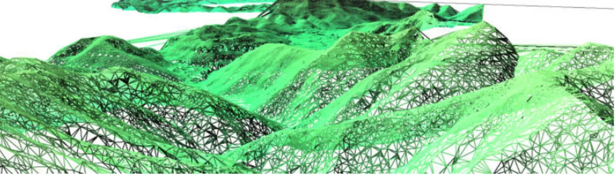
The 3DHRTS was tested with the terrain and highway design data from Guang-Wu expressway, from Shanwei in Guangdong province to Qingshui in Yunnan province. The triangulation irregular net digital terrain model is shown as Figure 5, the seamless join between highway modelling and the terrain model is shown as Figure 6, and the final result of the landscape rendering is shown as Figure 7.
Figure 5. Triangulation irregular net digital terrain model.
(a) The terrain model after CDT (b) The terrain model after the highway was added
Figure 6. The highway modelling.
Figure 7. The landscape after rendering. 5. CONCLUSION
With the development of computer hardware, computer graphics and the 3S (GIS, RS, GPS) technology, including these into the Road CAD system to improve the design result is both feasible and effective. This paper has explained the extendable and efficient system architecture and has analysed the function modules with which the system should be provided and the relationship between them. Based on the system architecture described above, the 3D terrain and highway models were built, integrated and rendered. 3DHRTS, although still a prototype system, demonstrates the advanced idea of using the real-time three-dimensional method to assess highway design results.
6. REFERENCES
[1] Cao Zhenyu and Qi Hua, 2004. 3D Geometrical modeling for highways. Railway Investigation and Surveying, 29, pp. 89-91.
[2] Chen Dongsheng, 2004. Application of 3D-animation to highway landscape design. Journal of Central South Highway Engineering, 29, pp. 89-90.
[3] Eberly, DH, 2001. 3D Game Engine Design: A Practical Approach to Real-Time Computer Graphics. Morgan Kaufmann Publishers, pp. 141-144.
[4] Fu Xinsha and Gong Dejun, 1998. Development of highway survey and design tchnology in China. China Journal of Highway and Transport, 11, pp. 26-28.
[5] Gamma, E, 2000. Design Patterns: Elements of Reusable Object Oriented Software. Addison Wesley Publishers, pp. 1-19.
[6] Lee, DT and Schachter, BJ, 1980. Two algorithms for constructing a Delaunay Triangulation. International Journal of Computer and Information Sciences, 9, pp. 219-242.
[7] Li Zhilin and Zhu Qing, 2003. Digital elevation model. Wuhan University Press, pp. 2-5, 15-20.
[8] Liu Xue Jun and Fu Xin Sha, 2001. Development and status quo of the theory and methods of digital terrain model based on triangulation irregular net (TIN). Journal of Changsha Communications University, 17, pp. 24-31.
[9] Shewchuk, J, 1996. Triangle: Engineering a 2D quality mesh generator and Delaunay triangulator. Proc. 1st Workshop on Applied Computational Geometry, pp. 124-133. [10] Song Zhanfeng, Zhan Zhenyan and Pu Hao, 2003. Study on method of constructing
road integrated 3D model. China Railway Science, 24, pp. 107-109.
[11] Tan Kim Heok and Daman, D, 2004. A review on level of detail. Proc. International Conference on Computer Graphics, Imaging and Visualization, CGIV 2004, 26-29 July 2004, pp. 70-75.
[12] Voronoi, G, 1998. Nouvelles applications des parameters continus, a la theorie des formes quadratiques, Deuxieme Memorie: Rechetches sut les Parrallelloedres Primitifs. Journal fur die Reine and Angewandte Mathematik, 134, pp. 198-287.
[13] Zhao Jianjun, Wang Qifu and Wang Xiaogang, 2005. Real-time 3D road animation based on digital terrain model. Computer Engineering, 31, pp. 196-197.