Vol.14, No.2 December 2003
2
Continued on page Yoichiro Matsumoto Professor, Department of Mechanical Engineering, The University of TokyoIntroduction
Ultrasound is widely applied in the clinical field today, such as ultrasound contrast agent imaging, High Intensity Focused Ultrasound (HIFU), Extracorporeal Lithotripsy, sonodynamic therapy. Some of these have a close relation to the dynamic behavior of micro bubbles and that of a bubble cloud. In an ultra-sound imaging, micro bubbles are used as contrast agents.
Extracorporeal Focused Ultrasound Lithotripsy
− Cavitation Control Lithotripsy −
4
Continued on page Mamoru MitsuishiProfessor, Department of Engineering Synthesis, School of Engineering The University of Tokyo
1. Introduction
Tele-medicine is expected to contribute to teamwork medical care, emergency care, local medical service difference correction, home care, patient load reduction, doctor load reduction and high-level medical education. There are several kinds for the tele-medicine such as tele-radiology, tele-pathology, tele-mentoring, tele-surgery and tele-education. This paper describes the construction of a minimally invasive sur-gical system as an example of remote surgery, and its results.
Development of a Remote Minimally-Invasive Surgical System
with Operational Environment Transmission Capability
6
Masaaki SatoProfessor, Program Leader
Department of Bioengineering and Robotics, Graduate School of Engineering, Tohoku University
Introduction
The 21st century COE(Center of Excellence)program was first-ly planned out in FY2002 by the Ministry of Education, Culture, Sports, Science and Technology(MEXT)according the proposal reported by the University Council in 1998,“A Vision for Universities in the 21st Century and Reform Measures”to be Distinctive Universities in a Competitive Environment.
The 21st Century COE Program“Future Medical Engineering
based on Bio-nanotechnology”in Tohoku University
7
Ryutaro HimenoDirector, Advanced Center for Computing and Communication Riken(The Institute of
Physical and Chemical Research)
We started Computational Bio-Mechanics research project(CBM project, here after)in 1999 at RIKEN. This project is five-year project but the second CBM project will follow it from April, 2004. The ultimate goal of this project is developing a live human model on computer system. The human model should breath, have a beating heart and blood flows inside, and walk. He should become sick or be injured. Yes, we are going to develop a human simulator.
Human Simulator
(a)High 46 ms,(b)High 46 ms + Low 2 cycles(CCL), (c)High 46 ms + Low 5 cycles (CCL), (d)Low 2 cycles,(e)Low 5 cycles,(For all the cases, high fre-quency is 3.82 MHz, low frefre-quency is 545 kHz.
Continued from page 1 In a HIFU treatment, micro bubbles are used to enhance the heating of the tis-sues. The acoustic cloud cavitation has a close rela-tionship with the efficiency of Extracorporeal Lithotripsy. There is a need to understand more pre-cisely the amplitude and the power spectrum of acoustic emission from micro bubbles to visualize the tissues and organs, to determine the heat deposition rate for the treatment of modeling tumors and to find the emitted shock pressure from the collapsing bub-ble cloud. In a HIFU application, high intensity ultrasound causes acoustic cavitation near the focal area. The violent collapse of cavitation bubble has a potential of causing tissue traumas, especially in the case in which the bubbles form a cloud. The maximum pressure in the cloud that reaches order of GPa is reported both in numerical and experimental studies. On the other hand in the study of ESWL (Extracorporeal Shock Wave Lithotripsy), the com-plex effect of cavitation has been known in the early stage of its research history and many researchers have investigated the role of the cavitation in ESWL. The studies were conducted both as the factor of tis-sue damage, and of stone comminution accelerator. In recently, cavitation control techniques by applying
skillful shock wave combinations have been proposed and effective results have been achieved. However, the main force that breaks the stone is still consid-ered to be the incident plane shock wave that has a 10∼60 mm focal region. Moreover cavitation col-lapse is utilized only to accelerate the stone com-minution.
Cavitation Control Lithotripsy
By utilizing two frequencies focused ultrasound, extracorporeal lithotripsy method, Cavitation Control Lithotripsy(CCL)is being developed, that can erode and chip away the renal stone solely by the violent collapse of the cavitation that is induced by focused ultrasound. If the cavitation phenomena are well controlled in time and space only at the stone sur-face, the extremely high-energy and high-pressure con-centration can be utilized as a main factor of renal stone disintegration. The concept of the method and the phenomena in the CCL protocol are explained and the results of the stone crushing are also dis-cussed. Fig.1 shows the schematic of CCL. First, higher frequency ultrasound is focused at the stone surface(Fig.1-1). It has a range about 1∼5 MHz in its frequency for a shorter wavelength than the characteristic length of the renal stone. It creates a hemispherical bubble cloud consisting of very tiny bubbles only at the stone surface(Fig.1-2). Immediately after the higher frequency is stopped, a short pulse of lower frequency ultrasound that has 100 kHz∼1
Extracorporeal Focused Ultrasound Lithotripsy
−
Cavitation Control Lithotripsy
−
Yoichiro Matsumoto Department of Mechanical Engineering, The University of Tokyo
Fig.1 Schematic of cloud cavitation control
Fig.2 Experimental set-up
Fig.3 Stable bubble cloud at different frequencies
MHz in its frequency is focused at the hemispheri-cal bubble cloud(Fig.1-3). The lower one reso-nantly forces the bubble cloud to oscillate(Fig.1-4). Accompanied with the bubble cloud forced oscilla-tion, shock wave propagates inward from the hemi-spherical bubble cloud(Fig.1-5). At the center of the bubble cloud, the bubbles near the center col-lapse violently while they emit an extremely high-pressure wave that reaches order of GPa. Therefore, only at the stone surface the stone is crushed result-ing in scoop-like indentations, with a high-energy con-centration and also with the minimum amount of cav-itation. The typical cavitation control ultrasound waveform is as follows:As indicated previously, high frequency ultrasound(bubble cloud creator)is imme-diately followed by low frequency ultrasound(cloud collapse inducer). The interval time should be long enough to dissolve all of the cavitation bubble into liquid. If this scheme can be finely controlled with-in cavitation area with-in space and the occurrence time of the bubble cloud collapse, a lithotripsy method uti-lizing only cavitation erosion can be developed that produces less tissue damage and more tiny fragments than conventional ESWL.
Behavior of the bubble cloud in CCL method The experimental set up is shown in Fig.2. The concave PZT ceramic diaphragm that have the nat-ural frequencies of 500 kHz is used for the ultra-sound transducer. It transmits higher amplitude of ultrasound at the frequencies of(2n+1)times of the fundamental frequencies than the other frequencies. Appropriate higher order harmonics coupled with fun-damental frequency is used to realize CCL waveform by one PZT transducer. The aluminum ball or arti-ficial stone, which is used as the crushing test mate-rial of the ESWL machine, is fixed at the focus point. The cavitation phenomena at the focal point of the ultrasound are photographed by the ultra high-speed camera. Needle type hydrophone is placed near the focal region to detect the synchronized signal of the shock wave emitted by the cavitation collapse.
High frequency focusing phase: Stable bubble cloud
Fig.3 shows the stable bubble clouds made by the single frequency ultrasound at the focal point. After 100 - 200 ms irradiation of the single frequency ultra-sound, stable bubble clouds are observed. With the bubble cloud growing in size, at its surface, almost the entire pressure wave is scattered and pressure wave does not proceed into the bubble cloud. At some point, the bubble cloud stops growing and becomes stable size. Then, there is a strong rela-tionship between the size and the ultrasound wave-length. At the focal point, because the standing wave field that is created by the incident and reflected ultrasound wave determines the pressure field, the size of stable bubble cloud is considered to be depen-dent on the wavelength. Fig.3 shows that the sizes of the area generated by the bubble cloud can be controlled with respect to the ultrasound frequency in the area restricted within some 100 mm, i.e., in the focused ultrasound field, acoustic cavitation at the solid surface can be well controlled in space.
Low frequency focusing phase:Collapse of bub ble cloud
The photographs of the bubble cloud forced into oscillation are shown in Fig.4. Immediately after 100 ms irradiation of 2.75 MHz ultrasound, 545 kHz pulse ultrasound is focused upon the cloud. The sta-ble bubsta-ble cloud is forced to oscillate by 545 kHz ultrasound. The bubble cloud shrinks at the positive phase of 545 kHz ultrasound decreasing each bubble radius, and then at the 4th frame, the bubble cloud is forced to collapse. Fig.5 shows the acoustic sig-nal that is taken 1.6 mm away from the focal point. In Fig.5, 4 points of peak amplitude against the occur-rence time that overlap the acoustic signal time his-tory are shown. This figure shows the CCL method triggers the bubble cloud collapse with a very high reproducibility. The standard deviation of the occur-rence time is 65 ns. The maximum pressures are about 3 MPa at 1.6 mm away. It is shown that
Figure5 Shock wave signal and peak amplitude occurrence Figure5 time of the cloud cavitation collapse
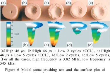
(a)High 46 ms,(b)High 46 ms + Low 2 cycles(CCL),(c)High 46 ms + Low 5 cycles(CCL),(d)Low 2 cycles,(e)Low 5 cycles, (For all the cases, high frequency is 3.82 MHz, low frequency is
545 kHz.
Figure 6 Model stone crushing test and the surface plot of Figure 6 the erosion shape
Continued from page 1
2. Overview of the developed system
The developed remote minimally invasive system consists of surgery site, multi-media cockpit and com-munication system. Images from the endoscope, the whole operation room, and of vital sign are displayed on the large display and the small display located close to the operator in the multi-media cockpit. Master manipulators for the left and right hands were also developed(Fig.1). They are equipped with multi-axis force sensors to feedback the force infor-mation detected at the slave manipulator. Position and orientation information from the master manipu-lator is transmitted to the slave manipumanipu-lator in the surgical site. The foot pedal is used to switch between the endoscope control and the forceps con-trol modes. Using the master manipulator, it is pos-sible to change the viewing direction of the endo-scope. The slave manipulator has three arms;the left and right arms hold the forceps and the middle
one holds the endoscope( Fig.2). Each arm is designed to hold the insert position of the trocar mechanically fixed for safety. During the operation, the insert position is fixed as the first step. Then three rotational, one translational and the grasping degrees of freedom are controlled.
3. Operational environment transmission and display To perform the tele-surgery, visual information of the whole operational room as well as visual infor-mation from the endoscope should be transmitted to the multi-media cockpit. The information of the assistant at the surgical site, status of the slave manip-ulator and the vital signs of the patient should also be transmitted.
Therefore, in our system, the combination or the selection of the visual information from the endo-scope, visual information of the abdominal region of the patient, visual information from the assistant and the slave manipulator and vital signs, such as an
elec-Development of a Remote Minimally-Invasive Surgical System with
Operational Environment Transmission Capability
Mamoru Mitsuishi Professor, Department of Engineering Synthesis, School of Engineering The University of Tokyo
cloud cavitation collapsing phenomena can be well controlled in time with a high pressure and energy concentration at the solid surface.
In vitro stone crushing tests
The crushing tests of model stone(diameter 10 mm, height 10 mm), which are used as the test mate-rial of ESWL machine, are conducted. The PRF (Pulse Repetition Frequency)of the ultrasound pulse and the amplifier voltage are fixed at 20 Hz and 1.6 kV(peak-to-peak). The irradiation time of the each waveform is 3 minutes. Fig.6 shows the picture and the plot of the indentation shape of model stones. The waveforms, high frequency only,(a), erode the stones a little, 1 mm in depth. In the case low fre-quency only waveforms,(d)and(e), erodes the stone more. 2 cycles and 5 cycles of low frequen-cy erode the stone 2.5 mm and 4.3 mm. In case (c)and(d), high and low frequency combination waveform, CCL waveform, the depth of the scoop indentation reaches 6 mm by cloud cavitation col-lapse. Especially in case(b), very acute hole is created, and there seems to be no damage at the sur-rounding surface of the stone. These results show by controlling acoustic cavitation phenomena,
high-pressure and high-energy concentration is realized within a fine spatial and timing resolution, in case (b). The estimated total break up time by CCL is comparable to the conventional ESWL methods. Also the resulting fragments are sufficiently small to pass through the urethra.
Concluding Remarks
An extracorporeal lithotripsy method, Cavitation Control Lithotripsy(CCL)is being developed utiliz-ing two frequencies focused ultrasound. By control-ling cloud cavitation phenomena, high-energy and high-pressure concentration only at the stone surface is obtained. Cavitation phenomena are well con-trolled both in time and space. The occurrence time of the bubble cloud collapse can be controlled with-in 65 ns, and the cavitation area that is generated by high frequency ultrasound can be controlled within 100 mm in space. A model stone is efficiently chipped away. The stone comminution mechanism is attrib-uted solely to the cavitation erosion. Compared with conventional ESWL, cavitation spatial range is nar-rower and total input energy is also smaller. The CCL method has the potential to provide a less inva-sive and more controllable lithotripsy system.
trocardiogram(ECG), can be transmitted(Fig.3). The transmitted visual information of the total oper-ation room environment is displayed on the large dis-play behind and the small disdis-play close to the oper-ator.
4. Active forceps with multi-axis force sensor The active forceps developed in this paper has the functions of rotating the forceps around its axis and grasping an object at the tip. It is possible to sep-arate the actuation and sensing, and the tool part. The tool part can be changed, for example from for-ceps to a radio knife.
The tool part is inserted in the human body. The tool part consists of only mechanical elements for easy sterilization and washing. The attachment unit was developed using a thrust bearing where the rota-tional motion around the forceps and grasping motion at tip can be independently transmitted. Translational motion of the rod for grasping is realized using a rack and pinion and a linear guide.
The grasping motion of the forceps is realized by pushing and pulling the rigid rod attached with the link mechanism at the forceps tip. A force sensor is located between the rod and the actuator(Fig.4). The pulling force is detected to estimate the grasp-ing force. In the developed system, a 1-axis force sensor based on a parallel plate structure is attached between the attachment unit and the linear actuator. A torque sensor where 4 thin plates are radially located is attached between the attachment unit and the motor for the rotation. It is possible to detect the torque around the forceps axis.
A 6-axis force sensor is attached between the active forceps and the slave manipulator. It is possible to detect the 3 directional forces and 3 moments. In the implemented system, all force sensors were orig-inally developed using strain gauges.
5. Experiment and results
In the experiment, the multi-media cockpit and the surgical site were located at the University of Tokyo and the animal experiment institution located in the Shizuoka, respectively. The distance between the
sites is approximately 150km. In the experiment, the gallbladder of a pig was removed. 3 ISDN lines were used in the experiment. 2 ISDN lines(256kpbs) and 1 ISDN line(128kbps)were used to transmit the visual and auditory, and control information including force information, respectively.
In the experiment, after trocars were inserted at the surgical site, the endoscope and forceps were insert-ed. Then the operation was executed from the remote multi-media cockpit. At first, the gallbladder was grasped using the left hand forceps. Then it was exfoliated using the right hand forceps. The fol-lowing operations were executed subsequently:cut-ting off the cystic duct and gallbladder, and collect-ing it. A radio knife was attached to the right slave manipulator while the cystic duct and gallbladder were cut off(Fig.5).
Using the developed system, it was possible to accomplish the series of operations. The measured time delays were approximately 350ms and 50ms, for the visual and auditory information, and control infor-mation transmission, respectively.
6. Conclusions
(1)Construction method of the remote minimally invasive surgical system was presented. The sys-tem was actually implemented.
(2)Using the developed system, a cholecystectomy for a pig was successfully executed over a dis-tance of approximately 150km.
(3)Time delay for the various information trans-missions was measured.
Fig.1 Master manipulater Fig.2 Slave manipulator Fig.5 Cholecystectomy for a pig Fig.3 Operational environment
Fig.3 transmission
Fig.4 Force sensors at the Fig.4 slave manipulator
Continued from page 1 In FY2002 applications were done in five different major fields, 1. Life Sciences, 2. Chemistry, Material Sciences, 3. Information Sciences, Electrical and Electronic Engineering, 4. Humanities, and 5. Interdisciplinary, Combined Fields, New Disciplines. Superb 113 proposals were in total selected for promoting advanced education and research in Japanese universities. Only our program was selected from purely engineering-oriented pro-posals in the field of life sciences. The main aim of our program is to promote the advanced educa-tion for students in Ph.D. course through advanced high technologies in biomedical engineering by sup-porting them financially as well as educationally.
Backgrounds
Technology is widely expected to provide answers to some of the medical and other problems faced by people in our aging society. Traditionally, Tohoku University has developed new technologies for the life sciences through cooperative research that has been undertaken by its engineering and medical schools. Advanced research at Tohoku University has led the way in the fields of cell function and biomolecular technology, nanomedicine, imaging and structure of biomolecules, and medical informatics. It is now crucial that we combine these advanced research activities into a systematic approach so that future biomedical engineering can be applied to sophisticated medical research and practice. This program aims to unite various technologies in order to develop the ultimate in prophylactic measures for age-dependent diseases, using tailor-made diagnostic and therapeutic procedures. The overall objective of this program is to form a global center of excellence in biomedical engineering. The active 18 members of this program widely belong to various departments from engineering to medical schools. To facilitate this process, the program will be rigorously assessed
by an independent committee composed of external members.
Plan for Formation of Research Center
a.Star t-up:The Administrative Center. In the first fiscal year, the Bionanotechnology Research Center in Mechanical Engineering, the Center for Translational and Advanced Animal Research on Human Diseases in the Graduate School of Medicine, and the Center for Interdisciplinary Research, formed the basis for the new center as shown in Fig.1. The Unit of Life and Biomedical Engineering in the Graduate School of Engineering will constitute the base for this center in the second year. Cooperative research centers will be established abroad.
b.Steering committee:Members include a chairper-son, four vice-chairs, and several active members. This committee deals with important issues con-cerning the administration.
c.Assessment committee:The members(five per-sons)of this committee are experts from other universities, and from related institutions or com-panies, who assess our activities at the end of each fiscal year.
d.Employment of foreign researchers:Active researchers, professors(full, associate or assistant)will be invited to undertake cooperative research at Tohoku University, as well as to discuss subjects of mutu-al interest and to teach students through confer-ence presentations and debates.
e.Research groups:Four research groups were imple-mented and cooperative research between the groups will be actively encouraged. The groups will study Cell function and biomolecular technology, Nanomedicine, Imaging and structure of biomolecules, and Medical informatics as shown in Fig.2. As one of the research projects in the nanomedicine group, a
3D-The
21
st Centur y COE Program
“
Future Medical Engineering
based on Bio-nanotechnology
”
in Tohoku University
Masaaki Sato Professor, Program Leader Department of Bioengineering and Robotics, Graduate School of Engineering, Tohoku University
stacked retinal prosthesis has been developed (Fig.3).
Education Implementation Plan
a. Faculty meetings:Educational policy, self-assess-ment, and an advisory system for students are dis-cussed and implemented.
b. New curriculum:A new curriculum for students was developed to enable students to acquire the necessary experience and knowledge of biomedical engineering.
c. Education center:An administration office for educational purposes was built where faculty and students can conduct research and further their edu-cation.
d. Nomadic education system:By means of compe-tition, students will be selected to participate in cooperative research at universities abroad. Students from overseas universities will also be selected and invited to our center.
e. Itinerant education system:By means of compe-tition, self-reliant students will be selected and trained individually under a special apprenticeship program with individual professors.
Summary
Advanced research in the field of biomedical engi-neering is undertaken in four areas:1. Cell function and biomolecular technology, 2. Nanomedicine, 3. Imaging and structure of biomolecules, and 4. Medical informatics. Students in the doctoral program are able to obtain funds, including funds to study abroad, by means of a competition among applicants. Students are expected to undertake original research and to be self-motivated in their work. Through this program, we intend to establish a unique, high-level center for research and education in biomedical engi-neering.
Human Simulator
R yutaro Himeno Director, Advanced Center for Computing and Communication Riken(The Institute of Physical and Chemical Research)
Continued from page 1 Of course, we do not know much about human physiology. We started the devel-opment in subjects of which governing equations we have already known. Those are 1)soft and hard tis-sue simulation, 2)circulatory system simulation and 3)human motion simulation based on kinematics.
1)Soft and hard tissue simulation
Fig.2 Three dimensional internal structure microscope and an output sample
image with 20micron resolution Fig.3 Strength testing device for Fig.3 medical materials
Eye ball and bone are our current targets of sim-ulation. A silicone band is fitted onto the wall of eye ball in the retina detachment operation. The band squeezed the eyeball. This process is simulat-ed to tell doctors to choose optimum properties of the band(Fig.1)For this simulation, we have devel-oped not only simulation software system but also a high-resolution geometry measurement system:3-D
Fig.1 Simulation of retina detachment operation
Editors: Yoichiro Matsumoto, Chisachi Kato Fax:81-3-5360-3508 International Activities Committee
Published by The Japan Society of Mechanical Engineers All Rights Reserved, Copyright ○c 2003 Shinanomachi-Rengakan Bldg, Shinanomachi 35, The Japan Society of Mechanical Engineers Shinjuku-ku, Tokyo 160-0016, Japan URL http://www.jsme.or.jp/English
14
2
Fig.4 Micro CT device to capture 3D structure of Cancellous bone
Fig.6 Fluid-structure coupling simulation for blood vessel Fig.6 and stenosis.
Fig.7 Flow vectors and pressure distribution in the left ventricle
Fig.9 Human gait motion Fig.8 Flow around the coil in an aneurism.
Internal Structure Microscope(Fig.2)and a strength testing device(Fig.3).
It is essential to know detailed inside structure of the bone for precise prediction of its strength. We have developed a micro CT device to get fine 3-D inside structure of the bone(Fig.4). Fig.5 shows a
result of an implant simulation.
2)Circulatory system simulation
We are developing not only basic algorithm for fluid-structure coupling model(Fig.6)but also prac-tical blood flow simulation system from medical images by MRA, CT or Ultrasonic imaging devices. Fig.7 shows flows in the left ventricle whose chang-ing geometry was taken by a ultrasonic imagchang-ing device. Fig.8 shows a simulation of inserted coil in aneurism of cerebral artery.
3)Human motion analysis
A musculoskeletal model is used for simulating human motion. Fig.9 shows a simulation of human gate motion when a muscle of the leg is damaged. This kind of simulation will help rehabilitation of patients.
We will start the second CBM project from April, 2004. We will integrate above three simulation to achieve a whole human body with various organs, bones, muscles, blood vessels and skins.