This is an
Accepted Manuscript
, which has been through the
Royal Society of Chemistry peer review process and has been
accepted for publication.
Accepted Manuscripts
are published online shortly after
acceptance, before technical editing, formatting and proof reading.
Using this free service, authors can make their results available
to the community, in citable form, before we publish the edited
article. We will replace this
Accepted Manuscript
with the edited
and formatted
Advance Article
as soon as it is available.
You can find more information about
Accepted Manuscripts
in the
Information for Authors
.
Please note that technical editing may introduce minor changes
to the text and/or graphics, which may alter content. The journal’s
standard
Terms & Conditions
and the
Ethical guidelines
still
apply. In no event shall the Royal Society of Chemistry be held
responsible for any errors or omissions in this
Accepted Manuscript
or any consequences arising from the use of any information it
contains.
Accepted Manuscript
ChemComm
Journal Name
RSC
Publishing
COMMUNICATION
Cite this: DOI: 10.1039/x0xx00000x
Received 00th January 2012, Accepted 00th January 2012 DOI: 10.1039/x0xx00000x
www.rsc.org/
Facile hydrothermal synthesis of CuFeO
2
hexagonal
platelets/rings and graphene composites as anode
material for lithium ion batteries
Yucheng Dong,
a,b*Chenwei Cao,
bYing-San Chui,
a,bJuan Antonio Zapien
a,b*Delafossite CuFeO2 hexagonal platelets/rings and graphene composites were synthesized by a low temperature hydrothermal method. The formation mechanism of CuFeO2 hexagonal platelets/rings follows the combined effects of both GO and NaOH. The obtained composites as anode material display a good battery performance with high reversible capacity, good rete capability and cyclic stability.
In recent years, lithium ion batteries (LIBs) have become the dominating power sources for portable electronics due to their high energy density and long cycle lifespan.1 Recently, the application for LIBs is expanding to a large scale, particularly electrical/hybrid vehicles and grid storage.2 However, graphite as the conventional anode material for LIBs cannot satisfy the increasing demands due to its low theoretical capacity (372 mAh g-1). Therefore, seeking alternative anode materials with a better electrochemical performance has become an instant task. Ternary transition metal oxides, such as CuFe2O4, CuCo2O4, and ZnFe2O4, have been widely studied as very appealing anode materials to replace graphite due to their high theoretical capacity.3 Compared with them, CuFeO2, the first known delafossite structure compound possesses stable compositions in the Cu-Fe-O ternary system, has seldom been investigated as anode materials for LIBs.4 The delafossite structure is constructed from alternate layers of two-dimensional close-packed copper cations with linear O-Cu+-O bonds and slightly distorted edge-shared Fe3+O
6 octahedra, and each oxygen is coordinated by four cations (one Cu+ and three Fe3+).5 Most of the synthesis methods of CuFeO2 involve high temperature process, such as high temperature solid state reactions,6 sol-gel method with an after-treatment at high temperature,7 or high temperature hydrothermal method.8 The delafossite CuFeO2 has attracted much attention due to its unique crystal structures and potential applications in catalyst, p-type conducting oxide, and antimicrobial material.5, 9 Recently, Qiu
et al. developed a low temperature hydrothermal method to prepare CuFeO2 crystals as an antimicrobial material.
9a
The feasibility of CuFeO2 crystals as anode material has been proved by Liu’s group in 2011.7b However, the particles aggregation occurs during the
cycling process and low conductivity lead to fast capacity fade and poor cycling performance, which limit its application in LIBs. Graphene is widely used to prepare various hybrid materials due to its unique electrical, mechanical, and surface properties. Graphene-based transition metal oxide composites have been widely reported in LIBs, the improved electrochemical performance due to the synergetic effect between graphene and transition metal oxides.10 The functional groups attached on graphene oxide (GO) sheets play an important role in nucleation and growth of nanomaterials.11 Recently, Bando et al. reported that the acidic functional groups (-OH and -CO(-OH) on GO can be used as etchants to fabricate a layered metal oxide nanoring-graphene hybrid.12 The nanoring on graphene would increase surface area and short Li+ ions transport length that lead to high electrochemical performance.
Here, we present a facile, one-pot, and low temperature (180 oC) hydrothermal method to prepare delafossite CuFeO2 hexagonal platelets/rings and graphene (CuFeO2/G) composites by using propionaldehyde as a reducing agent (see ESI for experimental details). The electrochemical performance of CuFeO2/G composites as anode material in LIBs was investigated. Compared with CuFeO2 crystals, the as-prepared CuFeO2/G composites exhibit better electrochemical performances, such as high specific capacity, good rate capability and cyclic stability.
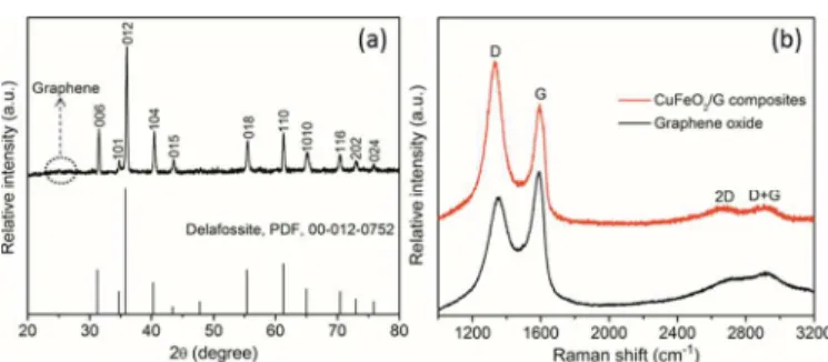
The typical XRD pattern of CuFeO2/G composites, Fig. 1(a), shows that all of the diffraction peaks and relative intensities are consistent with standard crystallographic data (Delafossite, PDF, 00-012-0752) which confirm the good crystallinity of the CuFeO2 phase. The CuFeO2/G composites crystallize in a rhombohedral structure and belong to the space group R-3m with a=3.031 Å, c=17.140 Å. An unconspicuous diffraction hump appearing in the range of ~24-28o was ascribed to the stacking of graphene sheets. The structural change of the carbon network occurring during the chemical processing form GO to graphene were characterized by Raman spectroscopy. Raman spectra of GO and CuFeO2/G composites are shown in Fig. 1(b). The Raman spectrum of GO has typical G and D bands located at 1592 and 1349 cm-1, respectively. A general characteristic of the reduction of GO is that the G band shifts to lower wavenumber. Raman spectrum of CuFeO2/G composites
ChemComm
Accepted
COMMUNICATION Journal Name
Fig. 1 (a) XRD pattern of CuFeO2/G composites; (b) Raman spectra of
GO and CuFeO2/G composites.
also possesses G and D bands, while the G band shifts to 1588 cm-1 suggesting the reduction of GO. The second benchmark of the reduction of GO is increase in peak intensity ratio between D and G bands (ID/IG). The ID/IG ratio for CuFeO2/G composites was calculated to be ~1.33 which is higher than that of GO (~0.84), further confirming the reduction of GO. The presence of a peak at 2667 cm-1 correaponds to the overtone of the D band and the peak at 2909 cm-1 ascribed to the (D+G) band which also shows a substantial increase in the disorder degree in graphene sheets.13
The morphology and microstructure of CuFeO2/G composites were characterized by SEM, TEM, and HRTEM. The typical SEM image of pure CuFeO2 crystals with well-defined edges, corners, and smooth surfaces of rhombohedra structure in overall size of ~0.8-2.5 µm is shown in Fig. 2(a). Fig. 2(b) and Fig. S1 (see ESI for details) present the representative morphology of CuFeO2/G composites, clearly revealing that the CuFeO2 crystals possessing hexagonal platelets and rings hybrid structures with a size range of ~1-3.0 µm are mixed with graphene sheets in the composites. The formation mechanism of CuFeO2 hexagonal platelets/rings follows the combined effect of both GO and NaOH. The CuFeO2 crystals with rhombohedra structure were obtained in the absence of GO (Fig. 2 (a)), thus we speculate that the oxygen-containing sites/defect sites on graphene sheets play as heterogeneous nucleation centers. In the hydrothermal process, the graphene may be functions as catalyst and surfactant to promote the formation of CuFeO2 crystals and limit the size of crystals.14 The concentration of alkali plays an important role in controlling the morphology of final products, and NaOH was used as catalyst and reagent in this reaction.15 The contrast experiments using GO (25 mg) and NaOH (0.4 g) were performed, respectively, while keeping other experiment conditions the same. No hexagonal rings were formed as shown in Fig. S2 (see ESI for details). The appropriate concentration of GO and NaOH is a crucial factor to obtain CuFeO2 hexagonal platelets/rings and graphene composites. Therefore, it is believed that the formation of hexagonal rings due to the introduction of crystal defects into the hexagonal platelets, and then the defects were etched more easily by NaOH to form irregular hexagonal rings. The ratio of obtained platelets and rings might be determined by the concentration of oxygen-containing surface groups of GO. The typical TEM images of single hexagonal platelets and rings in Fig. 2(c) further reveal the structure feature of CuFeO2 crystals in the composites. HRTEM image of the edge of an individual CuFeO2 crystal is shown in Fig. 2(d) and the corresponding Fourier transform of the high-resolution image is shown in its inset. The lattice spacing of 0.224 and 0.284 nm are in good agreement with the d-spacing of (104) and (006) planes of the delafossite CuFeO2. The result demonstrates the well-textured and single-crystalline nature of CuFeO2 in the composites.
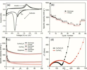
In order to demonstrate the feasibility of CuFeO2/G composites as anode material for LIBs, we conducted investigations on their electrochemical performance. The CV analysis was applied to
Fig. 2 SEM images of (a) CuFeO2 and (b) CuFeO2/G composites; (c)
TEM images of typical single CuFeO2 crystal; and (d) HRTEM image
of the edge of CuFeO2 crystal and its corresponding Fourier transform.
present the electrochemical details at a scan rate of 0.1 mV s-1 within a voltage window of 0.005-3 V (vs. Li+/Li), Fas shown in Fig. 3(a). The broad peak at ~0.73 V with an onset at ~1.15 V for the first cathodic cycle should be assigned to the reduction process CuFeO2 + 4Li+ + 4 e- → Cu0 + Fe0 + 2Li2O, 2C + Li
+
+ e- → LiC2, and the irreversible reaction related to the decomposition of the electrolyte.7b, 16 The first broad anodic peak appeared at ~1.68 V should be attributed to the oxidation of both the Cu0 and Fe0 to Cu2O and Fe2O3, respectively. After the first cycle, both cathodic and anodic peaks shift to the higher voltage ranges and the current decreases revealing the existence of certain degree of irreversibility of the redox reaction.17 In addition, the CV curves almost overlap after the first cycle, suggesting the insertion/extraction of lithium ions taking place to the same extent. The similar characteristics were also performed in the galvanostatic discharge-charge voltage profiles of CuFeO2/G composites at a current density of 100 mA
-1
between 0.005 and 3 V (Fig. S3, see ESI for details).
The rate capability (Fig. 3(b)) of CuFeO2/G composites was tested at various current rates from 0.1 C to 2 C for 10 cycles at each current rate (1 C=708 mAh g-1). It can be found that the capacities decrease as cycling current rates increase, which is caused by the low diffusion rate of the Li+ ions into anode at high rates.18 The first discharge and charge capacities of CuFeO2/G composites are 1571 and 944 mAh g-1 higher than the theoretical capacity of bulk CuFeO2 (708 mAh g-1), which are attributed to the formation of a pseudo-capacitive gel-like film.19 The initial capacity loss may result from the incomplete conversion reaction and irreversible lithium loss caused by the formation of a solid electrolyte interphase (SEI) layer.20 When the current rate was brought down to 0.2 C after 50 cycles, a stable highly reversible capacity of 607 mAh g-1 could be recovered. To further evaluate the cyclic stability, new cells were assembled and cycled at 0.2 C as illustrated in Fig. 3(c). For the CuFeO2 crystals, the reversible capacity gradually dropped to ~117 mAh g-1 after 100 cycles. The poor cycling performance of CuFeO
2 crystals could result from the inherent poor electronic and ionic conductivity. In contrast to CuFeO2/G composites, the reversible capacity decreased to ~640 mAh g-1 after 50 cycles, and then steadily increased to ~670 mAh g-1 after 100 cycles. The reversible capacity was maintained at ~440 mAh g-1 after 100 cycles tested at 1C as in Fig. S4 (see ESI for details). The capacity rises after prolonged cycling is a widespread phenomenon for transition metal
ChemComm
Accepted
Fig. 3 (a) CV and (b) rate capability of CuFeO2/G composites; (c)
cyclic stability of CuFeO2, graphene, and CuFeO2/G composites; and
(d) Nyquist plots (Z’ vs. –Z”) of CuFeO2 crystals and CuFeO2/G
composites.
oxides anode materials, which should be ascribed to a possible reactivation process.21 In order to investigate the electrochemical performance contribution of graphene in CuFeO2/G composites, we also measured the cycling performance of pure graphene electrode tested under the same electrochemical condition. As we can see, the capacity of pure graphene electrode dramatically decreased from 1320 to 230 mAh g-1 after 10 cycles. The morphology of CuFeO
2/G composites after 100 cycles at a current rate of 0.2 C is shown in Fig S4 (see ESI for details), which reveals that the structure of CuFeO2 crystals is still kept during cycling process. The stabilized structures result in enhanced electrochemical performance. Compared with the previous reported CuFeO2 as anode materials for LIBs,7b the materials reported here exhibit higher specific capacity, better rate capability and cyclic stability.
EIS was used to illustrate the origin of the improved electrochemical performance of CuFeO2/G composites. The Nyquist plots (Z’ vs. –Z”) of CuFeO2 crystals and CuFeO2/G composites were presented in Fig. 3(d). The semicircle at high frequency due to a passivation layer formed which creates corresponding impedance at the surface of working electrode and electrolyte.22 The semicircle dominating in medium frequency describes the charge transfer impedance (Rct) through the electrode/electrolyte interface, which is
considered as a large proportion of overall cell’s kinetic impedance.23 The inclined line known as Warburg impedance, represents the Li+ ions diffusion/transport in the electrolyte to the electrode surface.24 It is obvious that the semicircle diameter for the CuFeO2/G composites is smaller than that of CuFeO2 crystals, showing a lower Rct. In the low frequency region, the smaller
inclination of CuFeO2/G composites is a further evidence of the faster Li+ ions diffusion/transport behavior.
The enhanced electrochemical performance of CuFeO2/G composites should be originated from their structure features. The graphene sheets in the composites function as conductive network to improve the conductivity and as structural buffer to maintain the structure integrity during cycling process. The structure of platelets/rings could enlarge the contact area between electrolyte and active material, shorten Li+ ions transport length, and the pores in the oxide rings can buffer the volume variation during lithiation/delithiation process.12 Thus, the synergetic effect of conductive graphene and CuFeO2 hexagonal platelets/rings are
responsible for the enhanced electrochemical performance of CuFeO2/G composites.
In summary, we developed a facile, one-pot, and low temperature hydrothermal route to prepare CuFeO2/G composites as feasible anode material for LIBs. The CuFeO2/G composites exhibit enhanced electrochemical performance with high specific capacity of ~670 mAh g-1 up to 100 cycles at a current rate of 0.2 C, good rate capability and cyclic stability. The enhanced electrochemical performance originated from the synergetic effect between graphene and CuFeO2 hexagonal platelets/rings. Accordingly, we believe that the delafossite CuFeO2/G composites can be used as suitable anode candidate for LIBs and the preparation method could be extended to fabricate other delafossite-type oxides and graphene composites.
Acknowledgement
The authors acknowledge support by a grant from the Research Grants Council of the Hong Kong Special Administrative Region, China (Project No. CityU 103409).
Notes and references
a Center of super-Diamond and Advanced Films (COSDAF), City
University of Hong Kong, Hong Kong
b Department of Physics and Materials Science, City University of Hong
Kong, 83 Tat Chee Avenue, Kowloon, Hong Kong SAR, PR China E-mail: [email protected], [email protected]
Electronic Supplementary Information (ESI) available: [Experimental and characterization details, and Fig. S1-S5]. See DOI: 10.1039/c000000x/
1 Y. Idota, T. Kubota, A. Matsufuji, Y. Maekawa and T. Miyasaka, Science, 1997, 276, 1395.
2 B. Dunn, H. Kamath and J.-M. Tarascon, Science,2011, 334, 928. 3 (a) L.M. Jin, Y.C. Qiu,H. Deng, W.S. Li, H. Li and S.H. Yang,
Electrochim. Acta, 2011, 56, 9127; (b) Y. Sharma, N. Sharma, G.V. Subba Rao and B.V.R. Chowdari, J.Power Sources, 2007, 173, 495; (c) Y.F. Deng, Q.M. Zhang, S.D. Tang, L.T. Zhang, S.N. Deng, Z.C. Shi and G.H. Chen, Chem. Comm., 2011, 47, 6828.
4 W. Soller and A. J. Thompson, Phys. Rev., 1935, 47, 644.
5 W.C. Sheets, E. Mugnier, A. Barnabé, T.J. Marks and K.R. Poeppelmeier,
Chem. Mater., 2006, 18, 7.
6 (a) A.M. Sukeshini, H. Kobayashi, M. Tabuchi and H. Kageyama, Solid State Ionics, 2000, 128, 33; (b) D.H. Choi, I.B. Shim and C.S. Kim, J. Magn. Magn. Mater., 2008, 320, 575.
7 (a) H.Y. Chen and J.H. Wu, App. Sur. Sci., 2012, 258, 4844; (b) L. Lu, J.Z. Wang, X.B. Zhu, X.W. Gao and H.K. Liu, J. Power Sources, 2011, 196, 7025.
8 R.D. Shannon, D.B. Rogers and C.T. Prewitt, Inorg. Chem., 1971, 10, 713. 9 (a) X.Q. Qiu, M. Liu, K. Sunada, M. Miyauchi and K. Hashimoto, Chem.
Comm., 2012, 48, 7365; (b) C.G. Read, Y. Park and K.S. Choi, J. Phy. Chem. Lett., 2012, 3, 1872; (c) X.Y. Zhang, Y.B. Ding, H.Q. Tang, X.Y. Han, L.H. Zhu and N. Wang, Chem. Eng. J., 2014, 236, 251.
10 (a) M.J. Allen, V.C. Tung and R.B. Kaner, Chem. Rev., 2009, 110, 132. 11 H. Wang, J.T. Robinson, G. Diankov and H. Dai, J. Am. Chem. Soc., 2010,
132, 3270.
12 C. Nethravathi, C.R. Rajamathi, M. Rajamathi, X. Wang, U.K. Gautam, D. Golberg and Y. Bando, ACS Nano, 2014, 8, 2755.
ChemComm
Accepted
COMMUNICATION Journal Name
13 Z.H. Ni, H.M. Wang, J. Kasim, H.M. Fan, T. Yu, Y.H. Wu, Y.P. Feng and Z.X. Shen, Nano Lett., 2007, 7, 2758.
14 M.M. Liu, Y.Z. Lu and W. Chen, Adv. Funct. Mater.,2013, 23, 1289. 15 (a) T. Sugimoto, S. Waki, H. Itoh and A. Muramstsu, Colloids Surfaces A:
Physicochem. Eng. Aspects, 1996, 109, 155; (b) Y.P. Fan, G.J. You, Y. Li, Z. Zheng, H.R. Tan, Z.X. Shen, S.H. Tang and Y.P. Feng, J. Phys. Chem. C, 2009, 113, 9928.
16 Y.Z. Piao, H.S. Kim, Y.E. Sung and T. Hyeon, Chem.Comm., 2010, 46, 118.
17 Y.C. Dong, M.J. Hu, R.G. Ma, H. Cheng, S.L. Yang, Y.Y. Li and J. A. Zapien, CrystEngComm, 2013, 15, 1324.
18 N.Q. Zhao, S. Wu, C.N. He, Z.Y. Wang, C.S. Shi, E.Z. Liu and J.J. Li,
Carbon, 2013, 57, 130.
19 S. Laruelle, S. Grugeon, P. Poizot, M. Dolle, L. Dupont and J.M. Tarascon, J. Electrochem. Soc., 2002, 149, A627.
20 W.L. Yao, J. Yang, J.L. Wang and Y. Nuli, J. Electrochem. Soc., 2008,
155, A903.
21 T Zhu, J.S. Chen and X.W. Lou, J. Phys. Chem. C, 2011, 115, 9814. 22 M.D. Levi and D. Aurbach, J. Phy. Chem. B, 1997, 101, 4630.
23 S.A. Needham, G.X. Wang, K. Konstantinov, Y. Tournayre, Z. Lao and H.K. Liu, Electrochem. Solid-State Lett., 2006, 9, A315. 24 A.D. Fabio, A. Giorgi, M. Mastragostino and F. Soavi, J. Electrochem.
Soc., 2001, 148, A845.
ChemComm
Accepted