Towards automated provenance collection
for runtime models to record system history
Owen Reynolds
Antonio García-Domínguez
Nelly Bencomo
[email protected] [email protected] [email protected]SEA research group, EAS, Aston University Birmingham, United Kingdom
ABSTRACT
In highly dynamic environments, systems are expected to make decisions on the fly based on their observations that are bound to be partial. As such, the reasons for its runtime behaviour may be difficult to understand. In these cases, accountability is crucial, and decisions by the system need to be traceable. Logging is essential to support explanations of behaviour, but it poses challenges. Con-cerns about analysing massive logs have motivated the introduction of structured logging, however, knowing what to log and which details to include is still a challenge. Structured logs still do not necessarily relate events to each other, or indicate time intervals. We argue that logging changes to a runtime model in a provenance graph can mitigate some of these problems. The runtime model keeps only relevant details, therefore reducing the volume of the logs, while the provenance graph records causal connections be-tween the changes and the activities performed by the agents in the system that have introduced them. In this paper, we demonstrate a first version towards a reusable infrastructure for the automated construction of such a provenance graph. We apply it to a multi-threaded traffic simulation case study, with multiple concurrent agents managing different parts of the simulation. We show how the provenance graphs can support validating the system behaviour, and how a seeded fault is reflected in the provenance graphs.
CCS CONCEPTS
•Software and its engineering→System modeling languages;
Integration frameworks;Model-driven software engineering.
KEYWORDS
Provenance, runtime models, multi-threading, adaptation, self-explanation
Permission to make digital or hard copies of all or part of this work for personal or classroom use is granted without fee provided that copies are not made or distributed for profit or commercial advantage and that copies bear this notice and the full citation on the first page. Copyrights for components of this work owned by others than ACM must be honored. Abstracting with credit is permitted. To copy otherwise, or republish, to post on servers or to redistribute to lists, requires prior specific permission and/or a fee. Request permissions from [email protected].
SAM ’20, October 19–20, 2020, Virtual Event, Canada
© 2020 Association for Computing Machinery. ACM ISBN 978-1-4503-8140-6/20/10. . . $15.00 https://doi.org/10.1145/3419804.3420262
ACM Reference Format:
Owen Reynolds, Antonio García-Domínguez, and Nelly Bencomo. 2020. Towards automated provenance collection for runtime models to record system history. In12th System Analysis and Modelling Conference (SAM ’20), October 19–20, 2020, Virtual Event, Canada.ACM, New York, NY, USA, 10 pages. https://doi.org/10.1145/3419804.3420262
1
INTRODUCTION
Increasing complexity of software systems makes it difficult to determine the causes of behaviour at runtime [11]. An example of this can be seen with systems that offer concurrent activities, which present uncertainty about the order of events and interaction of activities that may occur at runtime [8]. In other cases, a system may need to make a decision over a body of information, and it may be difficult to discern exactly why that decision was made [5, 33]. Algorithmic accountability and the right to explanation is an important topic for software developers and society in general [34]. Explaining system behaviour requires runtime data to support the explanations [33, 37]. Event logging is a typical approach to col-lecting runtime data, where logs are therefore analysed to establish sequences of events or states [35]. However, analysis of logging data can be difficult and resource-intensive due to size-related issues. Structuring log files eases analysis of large logs [20]: by organising data (for example, into typed columns), analysis can be simplified through sorting and filtering.
Current approaches to logging can be time consuming: they are hard to build and refine [39]. Structured log files assist with analysis, but seem to offer little assistance when implementing logging. Part of the challenge with logging is knowing which events to log, and what content to use as a description [13]. Log files are sequential by nature, which presents additional challenges when trying to represent concurrent activities. Developers are left to overcome those problems by themselves, such as indicating time intervals or relationships between events.
A runtime model [7] provides an abstraction of the runtime system at a certain level, which discards details not relevant for its scope. Such a runtime model is available to the system itself to perform analysis [9]. The system is, therefore, self-aware of those aspects represented and abstracted by that runtime model [26]. By logging the changes to the model, rather than the changes to the system, we can abstract away details and therefore reduce the volume of the logs. Knowing theprovenanceof the changes [31], (i.e. who made those changes and for what reasons), creates the
needed causal connections that can help answer questions about the system’s behaviour. Such questions can be answered using provenance graphs, which relate systementitiesto theagentswho produced them, and theactivitiesthey were performing at the time.
We argue that runtime models combined with provenance graphs can create a logging-based infrastructure that solves some of the present issues with structured logs. For each change, it is possible to track who did it, and which activity caused it, within a concrete time interval. This approach to creation of logs can, therefore, be automated using a reusable provenance metamodel as a base, with system descriptions derived from a runtime model.
We propose the creation of a reusable infrastructure that captures the changes of a runtime model into a provenance graph, which can, later on, be queried to explain causes for behaviour. In this paper we present a first version of the architecture and evaluate a proof of concept implementation, applying it to a simple, but credible, multi-threaded system that uses a runtime model. The infrastructure produces logs related to changes and transforms them into a provenance graph that is ready and amenable to be queried. Reusability is also offered as the provenance graph conforms to a metamodel based on W3C PROV-DM [18] that is independent of the system’s runtime metamodel. The infrastructure also offers the concept ofprovenance scopes, a mechanism to automatically capture the model access events and changes produced by an agent performing an activity in the system. With the reusable provenance infrastructure, it is possible to reduce the effort needed to build a provenance graph of the evolution of the system over time: the number of lines of code in the case study grew by less than 3%.
This paper is structured as follows. Section 2 presents the con-cepts that underlie our research. Section 3 presents our approach to automated provenance collection for runtime models to record system history. Section 4 applies the approach to a traffic controller, states the research questions and show the experimental results. Section 5 further discusses the results obtained using the case study. We discuss related works in Section 6. Section 7 presents the con-clusions from these results, and outlines the areas of future work.
2
BACKGROUND
The ideas behind the present work emerge from several areas which we present as background. Autonomous and self-aware systems and the limitations of event logging motivate our work. Concepts from provenance and runtime models are used in our approach.
2.1
Autonomous and self-aware systems
Kephart and Chess presented their vision forautonomic computing back in 2001 [23], as they envisioned a future where systems be-came large and complex enough that architects would not be able to fully anticipate all the interactions in advance. Instead, many of these concerns would need to be dealt with during execution. They presented a system architecture known as the MAPE-K loop (Monitor, Analyze, Plan, Execute — over a Knowledge base) [3], where the system ran on top of models of its environment, its deci-sions, and their consequences, built over a feedback loop. The paper listed a number of self-management aspects of interest, such as self-configuration, self-optimisation, self-healing, or self-protection.
In more general terms, the research onself-aware systemsis pro-ducing systems that make decisions while explicitly taking into account (i.e. being aware of) their goals [36], requirements [33], or the time dimension [4]. A relevant self-awareness aspect is (self-) history-awareness. In [30], the authors argue that systems should be able to access their adaptation history to tailor future adapta-tions accordingly, and they call it history-awareness (HA). Further, they present four levels of HA that serve to frame explanation capabilities: 1) forensic self-explanation, 2) live HA explanation, 3) externally-guided and HA decision-making with explanation capabilities, and 4) automated HA systems.
This ability to make decisions on their own complicates their validation and verification, and in general introduces a problem of trust. This was already identified in [33], where it is argued that the system must garner the confidence of its users and developers by explaining why the system acted in a particular way at a certain time. Otherwise, they may not be adopted by the general public [1].
2.2
Event logging
One way to obtain explanations is to record what the system was seeing, doing, and “thinking” each time it made a decision. Tradi-tional logging frameworks (e.g. Log4j for Java [2]) can be used to produce a log of various events in the system. Log data may be used to identify system states or sequence of steps in a process for analysis after an event. This process has its own difficulties, as Yuan et al. [39] identified in a study of several high-profile open-source programs. Developers typically do not get their log messages on the first try: many have to be modified as afterthoughts, being changed in 18% of all revisions. 26% of those are related to the verbosity level, 27% are related to logging new variables, and 45% are about modifying the static text. With better tools, this time could have been saved and reinvested into the system itself.
Structured loggingtries to produce better logs by making them easier to parse with other tools (e.g. by using JSON/XML formats instead of plain text), and by providing more guidance on how to design the logged information. Legeza, Golubtsov, and Beyer briefly mention the use of JSON/XML for logs, and focus more on the guidance about their content [27]. They consider that a log message is divided into metadata (when, where, and its severity), and content (what happened, why, what’s next, and additional details). Legeza et al. say that when/where can be automated, the severity needs to be manually picked, and the content itself must be manually crafted in an iterative process.
Legeza et al. also mention the difficulties in correlating logs from different microservices in the same system, suggesting the addition of unique request IDs which are passed along all data paths for this purpose. In general, relating events (e.g. the start and end of an activity) can be difficult, especially in a highly concurrent system.
2.3
Provenance
When tracking the reasons that motivated an autonomous or self-aware system to make a decision, it may be useful to follow a more principled approach than inserting log statements at the own dis-cretion of the developer. The field ofdata provenancecan provide these principles. Pérez defined provenance to be “all the informa-tion and relainforma-tionships that contributed to the existence of a piece
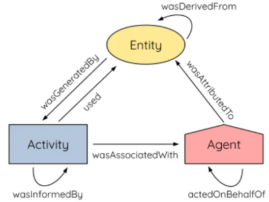
Figure 1: W3C PROV provenance graph structure
of data” [31]. Within that field, the Open Provenance Model (OPM) provides a standard reusable ontology to record provenance infor-mation [29]. OPM was the foundation for the W3C PROV prove-nance ontology, which is available in various notations: one of those is the PROV Data Model (PROV-DM) [18], which is used in our proposal (Section 3.1).
As shown in Figure 1, W3C PROV provenance graphs are formed by Agent nodes, Activity nodes, and Entity nodes. These nodes are connected with various kinds of edges that establish causal rela-tionships, such as“used”,“wasGeneratedBy”, or“wasDerivedFrom”. •Agentsidentify who is performing an activity ( “wasAsso-ciatedWith”): the exact level of granularity depends on the system. In a multi-threaded system, for example, each thread could be an agent. Delegation can be described as a rela-tionship of trust between two agents (“actedOnBehalfOf”), which may occur as the result of a user interaction that re-sults in a scheduled task. Agents generate entities through their activities (“wasAttributedTo”).
•Activitiesidentify high-level tasks performed by the sys-tem, and can be nested at multiple levels to represent sub-task relationships. Activities are related to entities through their inputs (“used”) and outputs (“wasGeneratedBy”). An activity using an entity generated by another activity “was-InformedBy”that activity. An activity takes place during a certain time interval.
•Entitiesrepresent system model features at the attribute and value level. When the value for an attribute changes, a new entity is created and related to its previous version (“wasDerivedFrom”). These entities could be grouped or cat-egorised like sub-assemblies, which enable higher level of abstraction through a reduction in details.
Provenance can be automatically generated by a system at run-time. We compare our approach with other automated provenance collection methods in Section 6.
2.4
Runtime models
Models have been used for a long time to support the documen-tation, development, and deployment of systems. More recently, models have started to be used during the execution of the system itself. Self-aware systems need to have a way to reflect upon their own behaviour or goals, and manipulate them to adapt as needed
to meet their goal. To do this, they maintain aruntime model[9]: “a causally connected self-representation of the associated system that emphasizes the structure, behavior, or goals of the system from a problem space perspective”. “Causally connected” means that a change in the runtime model will impact the system, just like a change in the system will be observable through the runtime model. A recent survey from Bencomo, Götz and Song [7] identified and classified 275 papers on runtime models. Many of these papers (123) used runtime models to build self-adaptive systems. 41 papers used runtime models to assure certain non-functional properties in a system, and 32 used runtime models for self-optimisation and self-organisation. The survey reports that most runtime models operate at high levels of abstraction (specifically, 131 at the archi-tecture level, and 32 at the goal level). However, there are still some runtime models at the process (12), context (20), and/or code (16) levels. Looking at these from a logging perspective, if our system maintained a causally connected runtime model at the desired level of abstraction, automatically recording the reasons for its changes would produce logs at that same level of abstraction. For instance, tracking changes in an architectural runtime model would produce architecture-level logs, while tracking changes in a process-level runtime model would produce process-level logs. Further abstrac-tion can potentially reduce storage and processing demands to the levels appropriate for the situation.
3
PROPOSED APPROACH
In the previous section, we provided a background on the chal-lenges presented by the need to explain the complex behaviour of autonomous and self-aware systems, and how traditional logging was difficult to get right in practice. We considered more principled ways to collect causal information with provenance ontologies. We also discussed how the causal connection and the use of higher levels of abstraction, provided by runtime models, offer support for more appropriate approaches for recording and treatment of logs. In this section, we outline our proposal for a reusable infras-tructure to capture the provenance of changes to the system in an automated manner and using runtime models. Our aim is to reduce the cost of adding this capability to an existing system. We first dis-cuss how to represent this information in a way that allows storage and processing demands to be adjustable to the current needs. We also outline the software architecture for such an instrumentation.
3.1
Data representation
In this paper, we consider systems that are self-aware, i.e. they explicitly maintain and use abstractions of their state as they run [6, 26]. Specifically, we use the termsystem modelfor such runtime models [10]. Tracking the changes of a model has already been studied in the literature (e.g. via model versioning [19] or filmstrip models [22]). However, to produce explanations about the system from those changes, their reasons (i.e.provenance) need to be explic-itly stated. Provenance, in our case, is underpinned by a structure able to record both the changes and their reasons, while keeping storage demands at a reasonable level.
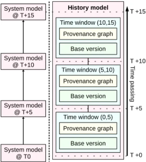
Figure 2 illustrates our design for ahistory model, which rep-resents the history of the system as a sequence oftime windows
Figure 2: History model
related to the system’s execution in chronological order. This his-tory modelis created alongside the system model and provides the basis for tracking. Each window has a reference to itsbase version of the system model, which represents its state when the time win-dow started, and aprovenance graphof the changes to the system model during that window laid on top of it. The use of windows independent from each other allows for “forgetting” past history, which is no longer relevant, by simply deleting those windows from the history model: for instance, we could keep one window per day, and only keep the windows for the last week.
By replaying the changes tracked in the provenance graph on top of the initial state, it is possible to recreate the base version of the following window. Beyond the concrete changes, the provenance graph also tracks the reasons for those changes, which can be used to provide explanations. In order to define what constitutes the reasons or provenance of a change, the following pieces of information are relevant:
•Who made the change?This may be either a part of the system (e.g. one of its execution threads), or a human in-teracting with the system. Therefore, the graph must keep track of the variousagentsparticipating in the system. •What was happening when the change was introduced?
On the one hand, the consumers of the explanations will likely only have a high-level view of all the activities taking place in the system. Therefore, rather than pointing them to a specific line in the code, it may be more useful to think about the high-level activity that this line was part of. On the other hand, most modern systems will have several activities taking place concurrently, e.g. through the use of multi-threading and/or multiple processes being run in the same or different machines. This means that tracking the order of the activities and their overlap is also necessary. •Which parts of the system model informed the change?
One way to identify problems in a system, or gain trust by providing explanations, is to examine which pieces of information guided a given decision. This can be done by capturing model accesses along with the changes made.
Figure 3: Reusable provenance collection layer components
In order to provide a formal structure for a provenance graph that integrates these pieces of information, a provenance ontology can be used. We have chosen W3C PROV-DM for this [18], as it is an established and validated standard which provides a usable data model that can be easily implemented (Section 2.3).
3.2
Data collection
After proposing a representation for the information, the next step is to show how to populate that history model. Manually modifying the system to produce the history model is a cumbersome and error-prone activity, where some of the interactions may not be captured. Instead, we propose to develop an instrumentation layer to be added into the system; this layer automatically populates the history model as the system interacts with its system model.
Figure 3 outlines the high-level components involved and their interaction. A set ofobserverswatch the writing and reading ac-tions performed by theagentsin the system model (e.g. execution threads). The agents send this information to amessage queue. The message queue is meanwhile read by acuratorthat runs on its own thread, and which populates the history model according to the structures shown in Figures 2 and 1.
The current proof-of-concept of our architecture follows the pro-cess described above. The design makes some assumptions about the system. The system is assumed to run on a single machine, and the model is shared in memory between threads in the same oper-ating system process. Further, model transactions ensure isolation between threads. Dealing with distributed models is part of our future work as explained later.
3.2.1 Observer. Theobserverintercepts any access to the system model by the agents, and records who performed the access. Record-ingwhodid it (the agent) implies the identification of which agent was doingwhat(the activity) when the agent read/modifiedwhich part of the model (the entity). This interception is dependent on the specific modelling technology used. For example, in the case of the well-known Eclipse Modeling Framework, the use of a spe-cialised EObject implementation may be an option. Another avail-able approach is the use ofaspect-oriented programming, where the interception would be treated as an aspect [24].
In our current version, we require all our model elements to inherit from a specialised EObject implementation which will in-tercept any model access and notify thethread observer for the
Listing 1: Java try-with-resources for activity scopes 1 try (var aScope = new ActivityScope (" ActivityName")) { 2 // ... model reads and writes ...
3 }
agent in question. Since each agent runs on its own thread, we automatically identify the agent through the name of its thread.
There are also different ways of identifying the activity. For example, it can be done via stack trace analysis, method- or class-level annotations, or with the use of dedicated "blocks" oractivity scopesthat span the code for the activity at hand. The specific syn-tax for these blocks would be language-specific. As suggested by Section 2.3, there is a tradeoff between level of detail and under-standability when choosing automatic or manual approaches to identify the activity. A fully-automated approach via stack traces could provide more detail, but manually added activity scopes may be closer to how a domain expert thinks about the system.
In the current prototype, we chose to manually add activity scopes for that reason. Our activity scopes are implemented through Javatry-with-resourcesblocks (see Listing 1), where resource acqui-sition marks the start of an activity, and resource release marks its end. It is important to note that scopes can be nested, as activities may have sub-activities within them. The observer keeps track of the stack of activity scopes, and associates model accesses with the activity at the top of the stack.
As mentioned before, each agent runs on its own thread, with its own thread observer collecting the notifications from the custom EObject instances. The observers communicate with the curator thread (detailed below) by addingmessagesto a thread-safe bounded blocking queue in the curator. Messages are tuples of the form(id, agent, activity, oldEntity, newEntity, commitTime):
•iduniquely identifies the message (mostly for debugging). •agentis a description of the Agent, with its name (the name
of the thread), and optionally the type and group.
•activitydescribes the Activity, which has its unique ID, name, and its start and ending time (if set).
•oldEntityandentitydescribe the entities associated to the old and new values of the accessed model element fea-ture. Entity descriptions include i) a unique ID, ii) the name, feature, and ID of the feature, iii) the value in question, iv) the access type, and v) the storage and in-memory version numbers for the object.
Our provenance layer makes a distinction between entity versions that are reflected on disk in the versioned model store (“storage versions”), and interim versions that are only kept in memory during the execution of the activity (“mem-ory versions”). Each modification to a model element feature increments its memory version, and a commit resets it to 0. Memory versions can be useful to track the exact sequence of values that a feature took during an activity, rather than just the values it took before and after the activity executed. •commitTime is only used when reporting acommit of a
model transaction, pointing to that instant.
3.2.2 Curator.The curator runs on its own thread as a loop that extracts and processes the messages arriving at its blocking queue.
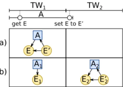
Figure 4: Options for representing an activity𝐴 spanning time windows𝑇 𝑊1and𝑇 𝑊2: a) keeping activities within the time window they started in, b) letting messages populate different time windows.
The curator operates in a stateless manner: it only uses the infor-mation in each message to update the provenance graph. When receiving a message, the curator follows these steps:
(1) If a model transaction has just been committed and enough time has elapsed, a new time window is started. This new time window uses the just-committed version in the model store as its base version, and has its own provenance graph. If not using a versioned model store, a base version may require a costly full copy of the system model.
(2) The provenance graph nodes for the agent and activity are searched by ID, and created if missing.
(3) If a model element feature has been read, search for the entity node and create it if missing. Add a“used”relation with the Activity in question. If the entity“wasGeneratedBy” another Activity, add a“wasInformedBy”relationship be-tween the current Activity and that one. Finally, if this required loading a model element from storage into memory, search or create an Entity for the stored version and add a “wasDerivedFrom”link with the memory-based entity node. (4) If a model element feature has been set, search or create the entity nodes forentityand foroldEntity(if set). Add a “wasAttributedTo”relation betweenentityand the Agent, and a“wasGeneratedBy”relation betweenentityand the Activity. IfoldEntityhas been set, add a relation “was-DerivedFrom”fromentitytooldEntity.
The time windows are memory-based in the current prototype for simplicity: this also helps speed up node searches. When a time window ends, it is moved into an Eclipse Connected Data Objects (CDO) repository to free memory [12]. The ability to dynamically unload and load parts of a large model is crucial for long-running systems, which may span over many time windows.
This use of multiple windows raises the question of how to distribute the provenance nodes across them. Figure 4 shows the two options that were considered. In this example, an activity𝐴 is spanning over both time windows𝑇 𝑊1 and𝑇 𝑊2, getting the value of entity𝐸during𝑇 𝑊1and setting it to𝐸′at the beginning of𝑇 𝑊2. Option a) is to record the time window in which𝐴started, and record𝐸and𝐸′in that time window. This complicates the curator, and can present problems if an activity never finishes (e.g. a continuously running background task in the system). Option b) creates a first pair of provenance nodes (𝐴1and𝐸1) for “get𝐸” in 𝑇 𝑊1, and then simply allows𝐴to continue into𝑇 𝑊2. When “set𝐸
Figure 5: Screenshot of the SUMO-based traffic simulation
to𝐸′” is processed, option b) will search for the nodes of𝐴,𝐸, and 𝐸′in the provenance graph of𝑇 𝑊2. Since they are not there, it will create a new set of provenance nodes for them:𝐴2for𝐴,𝐸2for𝐸 and𝐸′
2for𝐸
′. This increases the storage costs, but it simplifies the
process of “forgetting” past history: a time window strictly contains what happened in the system model during a certain interval.
Continuing with option b), it is important to note that activities and entities record their start and end instants. Thanks to this, it is possible to know during a query if an activity or entity existed before a certain time window. It is also possible to find out how many windows a particular activity spans (which may help with pruning), or check if an entity was created in a pruned time window.
4
CASE STUDY
The previous section described the general approach for our reusable provenance layer. This section will apply the provenance layer to an existing traffic simulation controlled by several agents that co-ordinate through a shared system model. The rest of the section introduces the case study, sets out the research questions, explains the experimental process, and provides the results.
4.1
Description of the case study
The system to be extended is a traffic simulation running on the open-source SUMO engine [16]. Figure 5 shows a partial view of the simulation at hand, which consists of two 4-way junctions; each managed by its ownjunction controllers. The controllers run concurrently, each using its own thread, and they share a connection to SUMO. The traffic lights in each intersection follow a cycle of phases: when a phase ends, the next one starts. The controllers can intervene to end phases earlier than the regular schedule. Each controller runs its own MAPE feedback loop:
•Monitor: reads the number of cars (yellow triangles) stopped at each lane area detector or LAD (blue rectangles). Reads the current state of the traffic lights, and checks the last plan that the other junction controller used (it may want to copy it). Records both pieces of information in the system model. •Analyze: checks if traffic is “jammed” at one of the LADs, by comparing the number of cars against a threshold𝐽(initially set to 3). Checks if the other controller ended a phase for its traffic lights in its last MAPE loop iteration. Records both pieces of information in the system model.
• Plan: based on the number of jammed LADs, it creates a plan for incrementing𝐽by one (if more than 2 are jammed), or decrementing𝐽by one (if less than 2 are jammed). If more than 2 LADs are jammed, or if the other junction controller ended a traffic light phase in its last iteration, then it creates a plan to end the current traffic light phase. Records current plans in the system model.
• Execute: conducts valid plans set out in Plan by communi-cating to SUMO and updating the system model. To protect against thrashing, Execute will block a phase change plan if the phase has been running for less than half of its duration. A class diagram for the metamodel that the system model con-forms to is shown in Figure 6. In general, aManagerprogram runs several concurrentSmartControllers. Each of the MAPE phases is represented by a type that collects its inputs (e.g. Monitor-Controls), and a type that collects its outputs (e.g.MonitorResults). There are also entities which represent the elements managed by each controller: theTrafficLights and theLaneAreaDetectors. This simulation is a proof-of-concept of a simple traffic manage-ment scenario, yet it captures the basic elemanage-ments of a more realistic simulation of city traffic. For the purposes of the case study, it shows a system which monitors the environment, analyses the situation, sets out plans to adjust itself, and attempts to execute those plans by interacting with the other participants. This creates information flows within the system that users and developers will want to follow through a provenance graph (e.g. to answer questions such as “why did the traffic lights end their phase at this point?”). It also has multiple concurrent agents interacting with the system model.
4.2
Research questions
A goal of this case study is to answer the following research ques-tions about our proposed reusable provenance layer:
(RQ1) What are the costs involved in the use of the provenance layer? This includes developer effort, additional processing time, and use of system memory and disk space.
(RQ2) How can we take advantage of the collected information? Given that visualisation will not scale past a certain com-plexity degree in the graph, we should be able to perform queries to trace the provenance of the changes in the system, or to test hypotheses about its behaviour over time. RQ1 will be evaluated by running the simulation with and with-out the instrumentation for the reusable provenance layer, com-paring space/time usage and the number of lines of code involved. RQ2 will be evaluated by developing sample queries illustrating common use cases.
4.3
RQ1: costs involved
In terms of developers’ efforts, the integration of the reusable prove-nance layer required adding the use of 16 activity scopes in two levels. First, an activity scope defines each of the MAPE phases. Next, each phase contained a further 3 nested activity scopes (e.g. Monitor had “monitor traffic light”, “monitor LAD”, and “moni-tor phase end from the other controller”). This required wrapping the relevant parts of the junction controller code in 16 try-with-resources blocks, as in Listing 1. Commits to CDO were modified so they would go through theThreadObserverfor the current agent:
Figure 6: Class diagram for the metamodel of the system model
Metric Provenance? Mean SD
Time No 32.34s 0.26s
Yes 32.34s 0.30s
Memory No 8.95MiB 0.04MiB
Yes 18.50MiB 0.21MiB
Table 1: RQ1: means and standard deviations of execution times and maximum memory usage, over 10 simulations across 200 ticks without/with the provenance layer.
this is needed to manage the distinction between memory and stor-age versions. The base class for the generated classes implementing the system metamodel was changed from the default CDOObject-Implto ourLoggingCDOObjectImpl. Finally, the simulation had to notify the curator about its completion.
The simulation grew after these changes from 823 lines of Java code to 846, as measured bysloccount2.26 [38] while ignoring generated code. This represents less than a 3% increase in code. The reusable observer and curator components are independent from this codebase, measuring at 943 lines (ignoring as well code automatically generated by EMF).
In order to measure changes in disk usage, the instrumented ver-sion of the simulation was run, and the sizes of the Derby databases used by CDO to store models were measured. The system model database took 864KiB and the history model database took 16MB. This shows that a history model can be much larger than its system model, and therefore, it justifies the need for pruning old history to manage storage demands.
To compare time and memory demands, the simulation uses a background thread to record total heap memory usage with the memory pool management beans present in Java ( MemoryPool-MXBean), once per second and once at the end of the execution. The simulation was run 10 times over 200 ticks with and without the reusable provenance layer. These executions were done on an Ubuntu 20.04 system with a Linux 5.4.0-42-generic kernel, using Oracle JDK 11.0.6, SUMO 1.4.0, and CDO 4.10 (as included in Eclipse 2020-06). The system ran on a Thinkpad X1 Carbon laptop with an i7-6600U CPU (dual-core with hyperthreading), with 16GB of RAM
and an SSD. Java was run with an initial heap size of 256MiB, and a maximum heap size of 512MiB.
Table 1 has the results for each option. The execution times have not been affected, showing that the time is dominated by the simulation itself and that the curator can run in the background without a noticeable impact. Peak memory usage has noticeably increased (roughly doubled), though as this is a small system model, it remained small as well. In general, the availability of CPUs with higher core counts may allow for additional services such as prove-nance to run on the background with less impact. However, more memory will undoubtedly be required.
4.4
RQ2: leveraging provenance
Provenance graphs can become very large and complex. There are various ways to extract information for them. In our previous work [32], graph visualisations were used to explore the informa-tion, however these quickly grew too large and complex to be of practical use. For that reason, this work focuses on query-based approaches to extracting information. For example, the survey by Herschel [21] mentions searching by item/time/type of element tracked, navigation (e.g. by following relationships or changing granularity levels), and structured query languages. Among these languages, common examples are XPath, SQL, SPARQL, or spe-cialisations of those. As we are using CDO with its default Derby backend, we could use SQL, but it would not translate to other CDO backends. Instead, we can write the query with any of the existing model query languages, such as OCL (supported out of the box by CDO), or the Epsilon Object Language (EOL) [25]. For the case study at hand, we have chosen to work with EOL, as it has recently gained support for transparent parallel execution [28]. Further, EOL can access models stored in CDO through the use of an Epsilon extension developed by one of the authors of this paper [14].
With the infrastructure ready, we can illustrate an example of how the provenance graph could be used to both identify the root cause of a defect we had deliberately introduced in the junction controllers, and to check that it has been fixed. Suppose that we are a new developer in Smart Traffic Inc., and on our first day we are
Listing 2: Excerpt of query Q1: find information used when a phase was ended
1 // 1. When was PhaseEnded set to true? 2 varePhaseEnded = Entity.all.select(ed |
3 ed.attr() == 'PhaseEnded'anded.bool()anded.isWrite()); 4 for(entJTinePhaseEnded) {
5 entJT.printLayer(0);
6 // 2. Where did the EndPhase this activity used come from? 7 for(entUsed1inentJT.wasGeneratedBy()?.Used 8 ?.selectOne(e | e.attr() == 'EndPhase')) { 9 entUsed1.printLayer(1);
10 // 3. What information was used when EndPhase was set?
11 for(entUsed2inentUsed1.wasGeneratedBy()?.Used) {
12 entUsed2?.printLayer(2);
13 }
14 '\n=end='.println(); 15 }}
Listing 3: Example of output of Q1 with faulty system 1 L0: PhaseEnded true > GenBy > executeEndPhase
2 L1: EndPhase true > GenBy > planEndPhase 3 L2: AnalysisResults AnalysisResults@OID268 4 L2: PlanToExecute PlanToExecute@OID267 5 L2: LADsJammed 5 > GenBy > analysisLADJammed 6 =end=
told to investigate an issue with a recent update to a smart junc-tion controller. The report says that the traffic lights are changing too often. All the developer knows is that the junctions follow a feedback loop, and that they have a provenance graph.
The developer would query the provenance graph to find the activity where the phase changed (PhaseEndedin ExecutionRe-sultswas set to true). Then, the developer would ask for the information used to make such a change, at several levels or lay-ers. The developer would run the EOL query in Listing 2: the
printLayerEOL context operation prints the name and value of the entity, and the name of the activity that generated it. The query would produce outputs such as those in Listing 3. The outputs show thatPhaseEndedwas set to true in theexecuteEndPhase
activity, which was informed byEndPhase, which was set to true inplanEndPhaseafter checkingLADsJammed, which was set to 5 inanalysisLADJammed. This is odd:LADsJammedshould never be larger than 4, the number of LADs at each junction.
The developer then knows that the problem is in the analysis-LADJammedactivity. At this point, the developer can look at the code (see Listing 4), to find out that someone inadvertently commented out an important line which resets theLADsJammedcounter before recalculation. After fixing the query, the developer can then let the system run further, to then re-run the query and check that the phases are ending for the correct reasons, producing an output such as in Listing 5. The output shows valid cases when the phase should end, i.e. when LADsJammed is above the threshold (set at 2 by default), as in line 4, or when copying the behaviour of the other controller as in line 10.
Listing 4: Excerpts of seeded fault located by Q1 1 // activity scope
2 try(var s =newActivityScope("analysisLADJammed")) { 3 analysisLADs(sc.getLaneAreaDetectors(),
4 sc.getMonitorResults(), sc.getAnalysisControls(), 5 sc.getAnalysisResults());
6 }
7 // method being called
8 public voidanalysisLADs(...) {
9 //sysAR.setLADsJammed(0); //←FAULT
10 for(LaneAreaDetector sysLAD : sysLADs) {
11 if(sysMR.getLADSeen().contains(sysLAD.getSumoID())) { 12 if(sysLAD.getJamLength() > sysAC.getJamThreshold()) {
13 sysAR.setLADsJammed(sysAR.getLADsJammed() + 1);
14 }}}}
Listing 5: Examples of output of Q1 with fixed system 1 L0: PhaseEnded true > GenBy > executeEndPhase
2 L1: EndPhase true > GenBy > planEndPhase
3 ...
4 L2: LADsJammed 3 > GenBy > analysisLADJammed 5 =end=
6 L0: PhaseEnded true > GenBy > executeEndPhase 7 L1: EndPhase true > GenBy > planEndPhase
8 ...
9 L2: LADsJammed 2 > GenBy > analysisLADJammed
10 L2: PlanToCopyPhaseEnd true > GenBy > analysisPhaseEndEvent 11 =end=
To save space, in this example we had the developer write the query in Listing 2 all at once. However, in practice the developer would most likely follow a number of steps to iteratively build the query: i) look for the cases whenPhaseEndedwas set, ii) look for what informed those cases, and finally iii) focus onEndPhaseat layer 1 and then look for what informed its value at the time. From Herschel’s point of view, there are elements of search, step-wise navigation, and structured querying in the example. As such, we believe EOL is expressive enough to cover most scenarios, and the ability to extend types with context operations (such asprintLater
orattr, which are not part of the history metamodel) would make it feasible to create a reusable library of functions to cover various scenarios. It may be possible to package these queries themselves into a UI for domain experts that covers the most common cases. Still, EOL may not be the most concise language for certain queries: for instance, a user may just want to see if there is a connection from a particular entity to a particular activity. For that case, the path expressions in graph query languages may be better suited. Evaluating these languages is part of our future work.
5
DISCUSSION
The reusable provenance layer has been applied to a traffic simu-lation case study with concurrent junction controllers operating on a shared system model in a CDO repository, using transactions to isolate threads. Applying this layer only required extending the simulation code by less than 3%, and did not have impact on the
simulation time. In the current version, the extensions were done manually, introducing activity scopes to the system. However, to improve that, we plan to use aspect-based programming [24] to introduce provenance as an orthogonal concern. This would keep the existing codebase unchanged, and would also remove its cur-rent dependency on the Eclipse Modeling Framework. As for the lack of impact on execution time, we consider it was largely due to the default rate set by SUMO. We will pursue further studies with simulations with higher data throughput.
The provenance layer did increase the storage demands (with a 16MB provenance layer for a 864kB system model) and the mem-ory demands (from 8.95MiB to 18.50MiB on average). While the absolute values are small, the relative increases suggest that fur-ther improvements can be done to reduce storage and memory overheads. Internally, the provenance graph records all individual accesses for each entity (e.g. two reads from the same activity): this history could be compressed, e.g. by only keeping the first read in a repeated series of reads from the same activity.
While this first version has stored provenance graphs in CDO, leveraging the additional capabilities of dedicated graph databases (e.g. path-oriented queries and mature graph-based visualisations) may be of interest. For that reason, we are considering creating an abstraction layer over the provenance graph storage, to therefore switch between CDO, graph databases, or other technologies (e.g. triple stores [40], popular in the provenance community).
The case study demonstrated how the provenance graph can be queried using EOL, traversing layers of explanation by asking for the entities that were used during a particular change. In its current version, the approach requires an expert user who has the knowledge to write EOL queries. We plan to study several ways to support non-expert users, such as the construction of a library of reusable queries for common scenarios, or the use of alternative query approaches such as the path-oriented queries in graph databases. We will also consider the relationships between nested activities, and provide ways to increase or decrease the level of granularity at which we study activities.
6
RELATED WORK
Our approach could be compared with other forms of automated provenance. The survey by Herschel et al. on provenance [21] states that there are largely three groups of solutions for automated collection of provenance in general programming languages. The first group requires explicit annotations to be added to the code. The second group collects provenance without requiring changes (e.g. via static analysis). A third group combines both approaches, with the more abstract and easier to understand information from manual annotations acting as a summary and the transparently collected information as a detailed record that can be explored. Ideally, a provenance collection approach should use this third approach as we have done in this work.
Two similar implementations of automated provenance collec-tion are D-TRACE and SPADE. D-TRACE automatically creates provenance graphs for the interactions between an application and the operating system, tracing system calls [17]. SPADE is an open-source provenance middleware with more flexible capabilities [15]: while running as a system service in the background, it can capture
operating system-level provenance (e.g. open files and connections), or application-level provenance. For application-level provenance, SPADE allows developers to manually introduce provenance infor-mation in a dedicated DSL, or to use compiler instrumentation to automatically track the provenance of certain function calls (e.g. via LLVM compiler options). Like SPADE, our approach enables application-level provenance, but we do not capture at an operating system level like D-TRACE. We are unique compared to both in our use of runtime models as a subject for provenance collection.
Parra et al. [30] showed a system that could turn the structured logs of a system into a temporal graph, giving users the ability to write structured queries about its evolution. They framed their approach into a gradual 4-level roadmap for introducing time-awareness into self-adaptive systems, and placed themselves at level 2 (live history-aware explanations). Their temporal graphs focus on decision processes and do not allow for history pruning, whereas our provenance graphs can cover all high-level activities that impact the system state, and can be pruned to keep the length of the history under control. The case study in the present work is at level 1 of their roadmap (forensic explanations), but the in-frastructure allows for level 2 use as it is possible to query the provenance graph while the system runs.
7
CONCLUSIONS AND FUTURE WORK
This paper proposed tracking the behaviour of self-adaptive soft-ware systems through an automated and efficient construction of provenance graphs of the runtime models used by the executing system to support explanation of runtime behaviour. Rather than recording everything that happens in the system, the approach abstracts away the details and records only the accesses to the higher-level system runtime model. The system runtime model raises the level of abstraction at which events in the system are recorded. Further, recording this information allows for a methodi-cal and better structured approach than those offered by traditional line-by-line text-oriented log messages.
This work has also described the design of a reusable provenance layer that can be applied to an existing system, with observers that watch what agents do, and a curator that collects the intercepted model accesses and builds a provenance graph from them. Multi-ple concurrent observers are allowed, and the curator processes accesses in a stateless way while splitting them over time windows. The chronologically ordered time windows represent a history model based on the system’s execution. The management of sep-arate time windows allows for forgetting past history when no longer relevant, allowing for efficiency and management of differ-ent storage demands.
There are several areas where this work can be expanded. In the current version, the queries require the specific knowledge of tech-nical users, and the answers provided can be techtech-nical. Being able to express queries and their results in a more natural manner (e.g. by accepting and generating inputs and outputs closer to natural language) would make the explanations more accessible to opera-tors and end users for example. We also foresee that our approach can support autonomy of the system, as the running system can use its own provenance graph to perform self-diagnosis when its system model becomes invalid. For instance, a watchdog agent in
the case study could have detected the invalidLADJammedvalue, and then it would have identified the responsible activity through a query, disabling it temporarily before warning a system operator. In terms of case studies, the shown case study is focused on a sys-tem model built around the MAPE-K loop. Additional case studies with larger systems and other types of runtime models according to the survey by Bencomo [7] would provide additional insights on how to leverage and further improve the reusable provenance layer at other levels of abstractions, which would be provided by goal-level or process-level models.
On the infrastructure side, a future line of work is to revisit the need for discrete time windows. The use of disjoint provenance graphs for each time window can complicate the writing of queries: some of the context operations in Listing 2 required additional code to handle discontinuities between time windows. We plan to com-pare the use of“continuesIn”links between activities and entities that span windows, with the use of a singlerolling provenance graph that is periodically pruned by a background process. Either way, users may wish to protect certain activities or entities from pruning, or specify different retention periods.
Finally, the proof-of-concept has only considered a system run-ning on a single machine. Tracking a distributed system would introduce new issues around data consistency between nodes, vis-ibility of the various areas of system model, and network com-munication complexities. There are ways to architect each solu-tion, e.g. with a centralised curator, or a distributed set of curators. While distributed models are a long-standing challenge in the [email protected] field [7], it is also a promising area of further work.
Acknowledgements: The work was partially funded by the Leverhulme Trust Research Fellowship (Grant RF-2019-548) and the EPSRC Research Project Twenty20Insight (Grant EP/T017627/1).
REFERENCES
[1] R. Andrews, J. Diederich, and A. Tickle. 1995. Survey and critique of techniques for extracting rules from trained artificial neural networks.Knowledge-Based Systems(1995). https://doi.org/10.1016/0950-7051(96)81920-4
[2] Apache Foundation. 2020. Log4J homepage. https://logging.apache.org/log4j/2.x/ Date last checked: August 1st, 2020.
[3] P. Arcaini, E. Riccobene, and P. Scandurra. 2015. Modeling and Analyzing MAPE-K Feedback Loops for Self-Adaptation. InProc. of SEAMS 2015. 13–23. [4] T. Becker, A. Agne, P. R. Lewis, et al. 2012. EPiCS: Engineering Proprioception
in Computing Systems. InIEEE 15th International Conference on Computational Science and Engineering. https://doi.org/10.1109/ICCSE.2012.56
[5] Victoria Bellotti and W. Keith Edwards. 2001. Intelligibility and Accountability: Human Considerations in Context-Aware Systems.Human–Computer Interaction
16 (2001), 193 – 212.
[6] N. Bencomo and L. H. Garcia Paucar. 2019. RaM: Causally-Connected and Requirements-Aware Runtime Models using Bayesian Learning. InProc. of MOD-ELS 2019. ACM, 216–226.
[7] N. Bencomo, S. Götz, and H. Song. 2019. [email protected]: a Guided Tour of the State-of-the-Art and Research Challenges.Software and Systems Modeling18, 5 (2019), 3049–3082. https://doi.org/10.1007/s10270-018-00712-x Springer-Verlag. [8] F. A. Bianchi, A. Margara, and M. Pezzè. 2018. A Survey of Recent Trends in Testing Concurrent Software Systems.IEEE Transactions on Software Engineering
44, 8 (2018), 747–783. https://doi.org/10/ggvqr6
[9] G. Blair, N. Bencomo, and R. B. France. 2009. Models@ run.time.Computer42, 10 (2009), 22–27. https://doi.org/10.1109/MC.2009.326
[10] G. S. Blair, N. Bencomo, and N. B. France. 2009. [email protected] Computer
42, 10 (2009), 22–27. https://doi.org/10.1109/MC.2009.326
[11] National Research Council. 2014.Complex Operational Decision Making in Net-worked Systems of Humans and Machines: A Multidisciplinary Approach. National Academies Press, Washington DC. https://doi.org/10.17226/18844
[12] Eclipse Foundation. 2019. CDO Model Repository. https://www.eclipse.org/cdo/ Date last checked: July 19th, 2020.
[13] Q. Fu, J. Zhu, W. Hu, et al. 2014. Where do developers log? an empirical study on logging practices in industry. InCompanion Proceedings of ICSE 2014. ACM, 24–33. https://doi.org/10/ggvqsz
[14] A. García-Domínguez and S. Madani. 2020. emc-cdo GitHub project. https: //github.com/epsilonlabs/emc-cdo Date last checked: August 1st, 2020. [15] A. Gehani and D. Tariq. 2012. SPADE: Support for Provenance Auditing in
Dis-tributed Environments. InMiddleware 2012 (LNCS). Springer, Berlin, Heidelberg, 101–120. https://doi.org/10.1007/978-3-642-35170-9_6
[16] German Aerospace Center. 2019. SUMO homepage. http://sumo.sourceforge.net/ Date last checked: August 2nd, 2020.
[17] E. Gessiou, V. Pappas, E. Athanasopoulos, et al. 2012. Towards a Universal Data Provenance Framework Using Dynamic Instrumentation. InInformation Security and Privacy Research. Vol. 376. Springer Berlin Heidelberg, 103–114. https://doi.org/10.1007/978-3-642-30436-1_9
[18] P. Groth and L. Moreau. 2013. PROV-Overview. Working Group Note. W3C. https://www.w3.org/TR/prov-overview/ Last checked: August 2nd, 2020. [19] M. Haeusler, T. Trojer, J. Kessler, et al. 2018. Combining Versioning and Metamodel
Evolution in the ChronoSphere Model Repository. InProc. of SOFSEM 2018. Edizioni della Normale, 153–167. https://doi.org/10.1007/978-3-319-73117-9_11 [20] S. He, J. Zhu, P. He, and M. R. Lyu. 2016. Experience Report: System Log Analysis for Anomaly Detection. In2016 IEEE 27th International Symposium on Software Reliability Engineering (ISSRE). 207–218.
[21] M. Herschel, R. Diestelkämper, and H. Ben Lahmar. 2017. A survey on provenance: What for? What form? What from? The VLDB Journal26, 6 (2017), 881–906. https://doi.org/10.1007/s00778-017-0486-1
[22] F. Hilken and M. Gogolla. 2016. Verifying Linear Temporal Logic Properties in UML/OCL Class Diagrams Using Filmstripping. In2016 Euromicro Conference on Digital System Design (DSD). 708–713. https://doi.org/10.1109/DSD.2016.42 [23] J. O. Kephart and D. M. Chess. 2003. The vision of autonomic computing.
Com-puter36, 1 (Jan. 2003), 41–50. https://doi.org/10.1109/MC.2003.1160055 [24] G. Kiczales, J. Lamping, A. Mendhekar, et al. 1997. Aspect-Oriented Programming.
InProceedings of ECOOP’97. LNCS, Vol. 1241. Springer-Verlag, Jyväskylä, Finland, 220–242. https://doi.org/10.1007/BFb0053381
[25] D. S. Kolovos, R. F. Paige, and F. Polack. 2006. The Epsilon Object Language (EOL). InProceedings of ECMDA-FA 2006. Bilbao, Spain.
[26] S. Kounev, P. Lewis, K. Bellman, N. Bencomo, et al. 2017.The Notion of Self-aware Computing. Springer International Publishing, Cham, 3–16. https://doi.org/10. 1007/978-3-319-47474-8_1
[27] V. Legeza, A. Golubtsov, and B. Beyer. 2019. Structured Logging: Crafting Useful Message Content.:login;Summer 2019, Vol. 44, No. 2 (2019). https://www.usenix. org/publications/login/summer2019/legeza
[28] S. Madani, D. S. Kolovos, and R. F. Paige. 2019. Towards optimisation of model queries : A parallel execution approach. Journal of Object Technology(2019). https://doi.org/10.5381/JOT.2019.18.2.A3
[29] L. Moreau, B. Clifford, J. Freire, et al. 2011. The Open Provenance Model core specification (v1.1).Future Generation Computer Systems27, 6 (2011), 743–756. https://doi.org/10.1016/j.future.2010.07.005
[30] J Parra-Ullauri, A. García-Domínguez, L. García-Paucar, and N. Bencomo. 2020. Temporal Models for History-Aware Explainability. In12th System Analysis and Modelling Conference (SAM ’20), October 19–20, 2020, Virtual Event, Canada. https: //doi.org/10.1145/3419804.3420276 To be published.
[31] B. Pérez, J. Rubio, and C. Sáenz-Adán. 2018. A systematic review of provenance systems.Knowledge and Information Systems57, 3 (Dec. 2018), 495–543. https: //doi.org/10/gf8q84
[32] O. Reynolds, A. García-Domínguez, and N. Bencomo. 2020. Automated Prove-nance Graphs for [email protected]. InACM/IEEE MODELS 2020 Companion Proceedings. https://doi.org/10.1145/3417990.3419503 To be published. [33] P. Sawyer, N. Bencomo, J. Whittle, E. Letier, and A. Finkelstein. 2010.
Requirements-Aware Systems: A Research Agenda for RE for Self-adaptive Sys-tems. InProceedings of RE’10. https://doi.org/10.1109/RE.2010.21
[34] Andrew D Selbst and Julia Powles. 2017. Meaningful information and the right to explanation.International Data Privacy Law7, 4 (12 2017), 233–242. https: //doi.org/10.1093/idpl/ipx022
[35] M. Szvetits and Uwe Zdun. 2013. Enhancing root cause analysis with runtime models and interactive visualizations.CEUR Workshop Proceedings1079 (2013). [36] G. Tamura, N. M. Villegas, H. A. Müller, et al. 2013. Improving context-awareness in self-adaptation using the DYNAMICO reference model. InProceedings of SEAMS. https://doi.org/10.1109/SEAMS.2013.6595502
[37] K. Welsh, N. Bencomo, P. Sawyer, and J. Whittle. 2014. Self-Explanation in Adaptive Systems Based on Runtime Goal-Based Models. 122–145. https://doi. org/10.1007/978-3-662-44871-7_5
[38] D. A. Wheeler. 2013. sloccount homepage. https://sourceforge.net/projects/ sloccount/ Date last checked: August 1st, 2020.
[39] D. Yuan, S. Park, and Y. Zhou. 2012. Characterizing logging practices in open-source software. InProceedings of ICSE 2012. IEEE Press, 102–112.
[40] M. Tamer Özsu. 2016. A survey of RDF data management systems.Frontiers of Computer Science10, 3 (June 2016), 418–432. https://doi.org/10.1007/s11704-016-5554-y