D
D
e
e
s
s
i
i
g
g
n
n
i
i
n
n
g
g
f
f
o
o
r
r
C
C
o
o
n
n
c
c
u
u
r
r
r
r
e
e
n
n
c
c
y
y
a
a
n
n
d
d
D
D
i
i
s
s
t
t
r
r
i
i
b
b
u
u
t
t
i
i
o
o
n
n
w
w
i
i
t
t
h
h
R
R
a
a
t
t
i
i
o
o
n
n
a
a
l
l
R
R
o
o
s
s
e
e
®®R
R
e
e
a
a
l
l
T
T
i
i
m
m
e
e
G
G
a
a
r
r
t
t
h
h
G
G
u
u
l
l
l
l
e
e
k
k
s
s
o
o
n
n
Introduction... 1
The Need for Concurrency and Distribution... 1
Concurrency Challenges ... 1
Distribution Challenges... 3
Solving Concurrency and Distribution challenges with Active Objects ... 4
Preventing Thread Interaction ... 5
Enabling Distribution ... 5
Mapping to Real-Time Operating Systems ... 6
Expressing Active Objects In UML ... 7
Capsule Class Representation ... 8
Structure Diagram... 8
Capsule Behavior ... 10
Inheritance ... 10
Rational Rose RealTime for Capsule Development... 11
Automatic Application Generation ... 12
Model observation and debugging ... 12
Additional support for distributed applications ... 12
An integrated suite solution... 12
Identifying Capsules in Designs ... 12
Use Case Approach ... 13
Architecture-Centric Approach... 13
Execution-based capsule discovery and refinement ... 14
Other uses of Capsules ... 14
Passive Objects... 15
Consolidation and refinement of Capsules ... 15
Summary ... 15
References ... 16
Introduction
Embedded systems have their computing power embedded (built into) the system, and thus the processors are typically not directly accessible by the user. Most embedded systems are also real-time. Such software is extremely prevalent in e-infrastructure and e-device development.
Concurrency and distribution are common in real-time embedded software design. Objects are often posed as solutions to these challenges. However, objects don’t automatically prevent undesired interaction among concurrent threads of execution, nor do they lend themselves to easy distribution. This paper outlines the challenges of concurrent distributed design and describes how active objects, captured as UML capsules using Rational® Rose RealTime, can provide a systematic solution. It concludes with heuristics for identifying and using capsules in design.
The Need for Concurrency and Distribution
Concurrency is when multiple activities occur during the same time interval. It is a natural phenomenon; in the real world many things are happening simultaneously. Such parallelism is especially prevalent in real-time embedded systems, where multiple and potentially independent and non-synchronized external stimuli are common (e.g., multiple users of a telephone system). Each stimulus can result in a concurrent thread of execution (instance of a use case) within the embedded system. For example, multiple telephone calls could be in progress, each of which requires it’s own complex sequence of actions to control the overall call. Software that interacts with the physical world has concurrency as an unavoidable design challenge.
These embedded systems are often distributed. They are interconnected with one another through networks to perform their complete function. For example, the telephone system is a complex global network of real-time embedded systems, ranging from massive central office switches to compact cell phones. This
connectivity is not limited to just geographical distribution, as many embedded systems contain an internal network of processors to perform their function. For example, a photocopier exploits the power of multiple processors to control naturally concurrent activities such as paper feed, image capture, and output control. Distribution both increases the concurrency of stimuli to each embedded system and the complexity of the coordination required among systems.
Concurrency and distribution can also be used to increase the performance and controllability of systems. Multiple processors can be used to perform tasks in parallel to speed up computational work. Within a single processor, multitasking can increase responsiveness by preventing one activity from blocking another (e.g., waiting for input). Concurrency can be used to speed up the startup of a system by processing the actions to get each component ready for operation in parallel, rather than initializing each one sequentially.
Controllability of the system can also be enhanced by concurrency. For example, a process can be started or stopped mid-stream by other concurrent processes. The above capabilities would be difficult to achieve without concurrent software.
The next two sections expand on the challenges of concurrency and distribution.
Concurrency Challenges
With concurrency being so natural in the problem domain and offering many design advantages, why is the design of concurrent software so difficult? If concurrent activities and thus the software components that supported them were independent, design could be simple. Software could be written to deal with each thread of execution in a sequential and non-synchronized fashion. Unfortunately independence is rare. Most problems with concurrent software arise from the coordination required to manage interactions among concurrent activities.
Highway traffic is a real-world analogy. Vehicles on divided highways have little interaction and thus there are few coordination problems other than staying a safe distance from the car in front of you. Parallel traffic streams in adjacent lanes require additional coordination for safety (e.g., lane changes). The intersection of two roads and thus streams of traffic causes significant interaction problems requiring careful coordination, especially where there are no traffic lights.
In a software system, an instance of a use case translates to a thread of execution inside the system, usually involving multiple objects interacting with each other in a complex sequence. Like the highway intersection example, often these concurrent threads intersect the same objects at a point in time. Figure 1 shows the various execution threads or use cases that might flow through a system, and the potential for intersection.
Figure 1: Interacting Threads
These intersections span the spectrum from very high level interactions (e.g., two phone users trying to call the same person at the same time) to low level problems such as two procedures both trying to modify the same data at the same time.
Interaction among concurrent software threads can cause many problems. A common situation is race conditions. Whenever multiple threads of execution have access to the same information (e.g., states or state variables), concurrency control is necessary to ensure that one thread does not modify the state while the other is performing a state-dependent operation. Simultaneous attempts to modify the same state information could result in state inconsistency.
Objects are often proposed as a solution to building complex concurrent systems where such interaction is common. Objects package data (variables and state), and the procedures that manipulate them into a cohesive component. They encapsulate the specific implementation of that object and provide an interface (methods) by which other objects may interact with it. Objects often model real world entities or concepts, and interact with other objects by exchanging messages. At first glance, it would appear that since objects offer very controlled access to state information, they automatically solve interaction problems.
The challenge is that most objects in languages such as C++ are passive; they can not independently initiate a control activity but rather rely on an externally provided thread of execution to power them. When there are multiple threads of execution in a system to handle concurrency, these multiple threads could be active in the same passive object at the same time, as often objects are involved in several use cases. Figure 2 illustrates this situation. Circles represent the passive objects. The shaded inside of each object is its state information, and the segmented outer ring is the set of procedures (methods) which define the object’s behavior.
Figure 2: Threads through passive objects
This intra-object concurrency can cause the same interaction problems that system concurrency brings, such as the potential for race conditions when multiple threads of execution have access to the same data as happens with object B in Figure 2. One might have thought that data encapsulation would solve this issue. The problem, however, is that passive objects do not encapsulate the thread of execution. Any circumstance where an object interrupts the processing of a message to process another message creates the possibility of race conditions, and thus requires the use of standard concurrency management techniques such as critical regions. Such concurrency controls, in turn, often open up the possibility of deadlock.
Unfortunately, designers rarely foresee and thus handle properly all the thread interaction problems that might arise in a running system in the field. This detracts from the dependability of such systems, as they tend to fail in often mysterious and unrepeatable ways as a result.
Distribution Challenges
Often the distribution scheme for objects (i.e., what processors the various objects reside on) is heavily influenced by the hardware architecture and educated guesses of performance impacts. These distribution chemes are often designed early in the project.
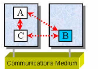
Figure 3 is an example of an initial distribution scheme involving communication among three main objects (A, B, and C), with solid lines indicating local communication and dotted lines indicating remote
communication over the network underlying the two processing nodes. At design inception, the developers expect that objects A and B have the highest degree of communication and thus are co-located on the same processor. Object C resides on the other processing node based on an expectation that it incurs high processing demands and is communicated with infrequently.
However, as more experience is gained with that initial distribution scheme, the developers find that there is much higher communication between objects A and C than between objects A and B, and that B has a much higher processing demand than either A or C. In that case, to better match the real requirements the distribution scheme evolves to that shown in Figure 4. That topology increases the performance of communications between A and C, and better balances the processing loads of the two nodes.
Figure 4: Evolved Distribution Scheme
The above example is very general, but representative of the design changes that are required as designers learn more about the requirements of the system and the processing and networking performance of their designs. This raises a key requirement for distributed designs to be flexible. Developers need the ability to easily change their distribution scheme as they iterate through the design, without significant design rework. Changes in the physical configuration of the system may necessitate changes in the distribution scheme, either during initial hardware development or as a result of technology changes during the product’s evolution (e.g., faster processors or different network transport mechanisms). The distribution scheme may even have to change dynamically (i.e., while the system is running) to best distribute objects for optimum performance. For example, under times of high demand certain objects may need more dedicated processing power.
To provide distribution flexibility, ideally the design approach should support location transparency. With location transparency, objects should not be concerned with the actual physical location of the target objects they are communicating with (i.e., whether they are in the same process, on the same processor, on another processor on the bus, or on the Internet). When communication is remote, designers should be isolated from the details of finding objects, using the underlying network to communicate with them, and so on.
Objects built to exploit location transparency are more adaptable to change and have a longer useful design life. In addition, the objects are much more reusable, as they all exploit a common distribution infrastructure they can plug into, and their design is de-coupled from the physical architecture.
Are objects naturally distributable? As with concurrency, the answer is “not quite”. Objects have
encapsulation, but it is typically one-way only. An invoking object does not know the internals of the object it is invoking, but it does know which object it is invoking and where it is.
Solving Concurrency and Distribution challenges with Active Objects
A best practice solution to handling concurrency and distribution is the active object design pattern. Active objects help address the concurrency interaction problem of passive objects. Like passive objects, they encapsulate data. However, they can also initiate control activity, which they do by having their own encapsulated thread of execution. These concurrent components can be implemented by using thread or process mechanisms supported by the real-time operating system (RTOS) the application runs upon. Active objects also address distribution by providing highly encapsulated interfaces to their environment.
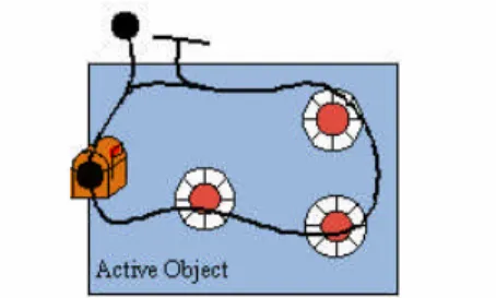
Complex systems are almost always constructed hierarchically. Active objects not only have their own behavior but they can also contain other passive and active objects. Figure 5 shows an active object encapsulating three passive objects, and a potential thread of execution through these objects.
Fig. 5: Encapsulating passive objects
When an active object is created, it is given its own thread of execution, which the object encapsulates until it dies. To support both asynchronous and synchronous communication with other active objects, each active object has a message queue or mailbox. The active object is sitting idle in a particular state until the arrival of a message. On message reception, the object executes whatever code is appropriate to process the message.
Preventing Thread Interaction
Run-to-completion semantics are critical for active objects to prevent thread interaction problems. Messages that arrive while the object is busy are put in a queue. When the object completes the processing of a message (i.e., is in its new state), it picks up or waits for the next message in the queue. With this run-to-completion approach, an active object requires that an operation (i.e., the response to an event) that has started be fully completed by that active object before another one can commence. It will not try to process new messages in the middle of processing the current message.
This run-to-completion approach ensures that there are never concurrent threads of execution inside an active object. Thus any passive objects encapsulated by an active object do not need to be protected against concurrency conflicts since it is guaranteed that only one thread can pass through them – the single thread of their containing active object. It is not necessary to search out and identify critical regions to prevent race conditions since each operation of an active object is an implicit critical region. This simplifies the writing of concurrent applications and increases reliability.
Run-to-completion semantics sometimes raise developer concerns about system performance. However, run-to-completion does not mean that the thread executing the processing of a message can never be preempted. As with any multi-tasking system, a higher-priority thread for one active object can preempt the lower-priority thread of another active object. When the higher-lower-priority thread completes its run, the lower-lower-priority one can continue. Time slicing can still occur among threads of equal priority. Thus the advantages of scheduling among active objects and prioritization are still preserved, while at the same time this interleaving of executions will not lead to concurrency conflicts as long as all passive objects are encapsulated within their respective active objects.
Enabling Distribution
Active objects enable distribution by highly encapsulated interfaces as shown in Figure 6. Active objects only communicate through ports that are either asynchronous or synchronous message based interfaces with well-defined protocols. A message is received on a port. That message gets processed by the internal behavior of the active object and the active object may respond by sending messages out through its ports.
Asynchronous message passing prevents blocking (having to wait for the object being communicated with o respond before the sending object can continue its execution).
Figure 6: Active Object
Ports support the concept of two-way interface encapsulation, as shown in Figure 7. An object sends messages (shown by the solid arrows) to the port rather than to the destination object, and thus needs not know the location of the destination object. The port relays the message to the destination object’s port (indicated by the dashed arrows). This two-way encapsulation provides the necessary location transparency by making the object insensitive to who it is communicating with, and thus the object is not dependent on its specific distribution environment. This is similar to a hardware integrated circuit, that just sends
information to/from its pins but does not know what specific circuit topology it is being used in. As a result, active objects adapt well to various reuse and distribution situations.
Figure 7: Two-way interface encapsulation
Mapping to Real-Time Operating Systems
Active objects can be mapped to a variety of real-time operating system concepts. For example, active objects sharing a single operating system thread coupled with a simple active object scheduler can provide very efficient, lightweight concurrency. Various active objects can be mapped to different operating system threads, thus isolating blocking components. Operating system processes can be used for maximum isolation (e.g., separate processes are needed if programs need to be started up and shut down independently). Separate processors can be used for physical distribution or for increased processing horsepower.
Active objects are a powerful design technique. Many developers consider active objects the foundation for component-based design. As such, it is important that developers have modeling language support for active objects. The next section describes how the active object concept can be elegantly expressed in UML.
Expressing Active Objects In UML
The Unified Modeling Language (UML) as defined in [UML Guide, UML Ref] is becoming the standard technique for graphical design of real-time embedded systems. UML use case, class, state, collaboration, sequence, component, and deployment views provide a good foundation for real-time embedded software development. UML includes the basic ability to tag objects that have their own thread of control as “active”.
UML also supports the concept of profiles, the packaging of design patterns for a particular problem domain usage of UML (e.g., web, business, database, real-time, etc.). Jim Rumbaugh and Bran Selic of Rational Software have collaborated on a UML profile to address concurrency and distribution, using standard UML extensibility mechanisms. These optimizations are focussed on rendering the active object concept as previously described, via capsules, ports, protocols, and connectors.
Capsules bring additional concepts to UML active objects such as run-to-completion semantics and full encapsulation provided by message-based interface ports. Capsules can be used throughout development, from the high level capture of architectures through to the expression of low-level concurrent design components and test harnesses, as shown in Figure 8. Capsules are not only best practice patterns for concurrent and distributed designs, but they provide excellent mechanisms for capturing the patterns relevant to specific applications.
Figure 8: Systems as hierarchies of capsules
To support hierarchical development, capsules can contain other sub-capsules and passive objects.
Hierarchical decomposition is key to handling design complexity, as diagrams with many (i.e., greater than 7) objects create high cognitive complexity. By grouping objects hierarchically, communication paths are clearer, diagrams are much simpler, and partitioning is easier. This hierarchical decomposition provides a concrete mechanism for capturing and evolving software architecture. There is no limit on the
Capsule Class Representation
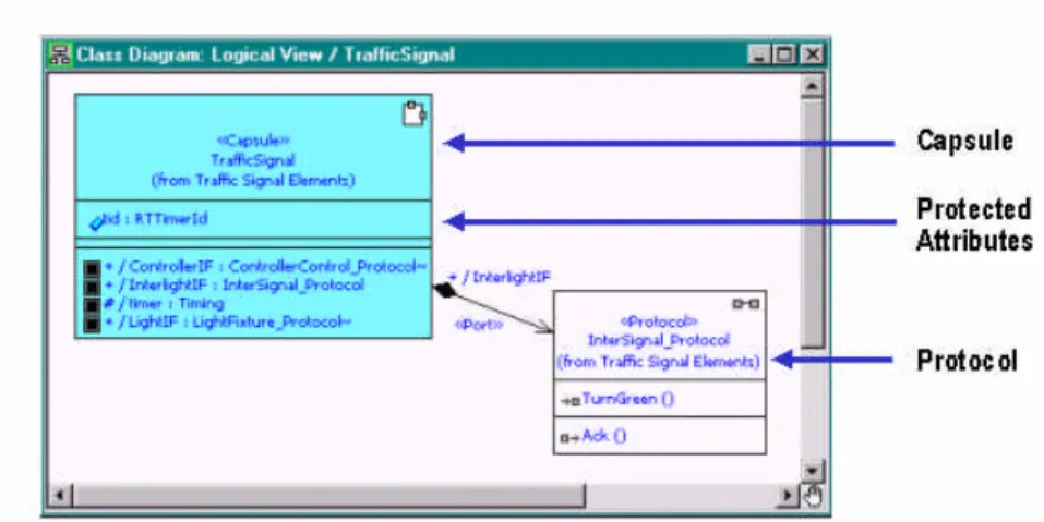
A capsule is represented by the «capsule» stereotype of Class with a certain set of constraints (e.g., run-to-completion semantics). The class diagram notation for capsules uses standard UML conventions as shown in Figure 9.
Figure 9 – Capsule Class Diagram
The stereotype name appears above the class name in the name compartment of the class rectangle. An optional special icon associated with the stereotype may appear in the upper right-hand corner of the name compartment. A capsule encapsulates it’s own protected attributes (passive objects), and can also contain other sub-capsules.
In capsule class diagrams, the ports of a capsule are listed in a labeled list compartment, taking advantage of the UML tagged value feature that allows the addition of specific named compartments. Capsules interact with their surroundings via messages that flow through ports. Each port plays a particular role in a collaboration that a capsule has with other capsules, and is analogous to the message queue described in active objects. For example, a terminal handler in a telephone system design may have various ports to capture the divergent roles it plays (e.g., it’s part in audio calls, it’s part in data connections, it’s association in various administration and maintenance functions, etc).
Each port is associated with a protocol that defines the valid flow of information (signal/message names and optional passive data objects) that passes through it. An example of a protocol is the collaboration required between the telephone subscriber and the switch to establish a telephone call, including the sequence of messages such as the sending and receiving of off-hook signals, dial tones, dialed digits, alerting tones, etc.
Structure Diagram
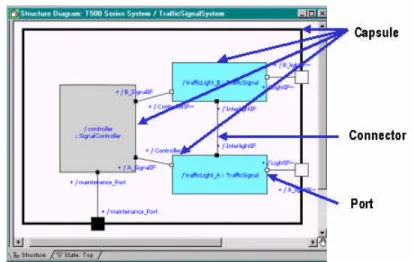
The internal structure of a capsule is modeled by a UML capsule collaboration, referred to as a structure diagram, as illustrated in Figure 10. This diagram shows structural containment and the communication relationships among capsules. For example, a traffic light system may be modeled as a number of capsules, including a traffic signal capsule that represents the lights for each direction of the intersection (i.e., North/South versus East/West) and a controller capsule that tells each traffic signal to go into normal operation mode.
Figure 10 : Structure: Containment and Communication
To reduce visual clutter, ports are shown in iconified form, represented by small squares. Port icons that straddle the boundary of the corresponding capsule represent public ports. This shorthand notation allows them to be connected both from inside and outside the capsule without unnecessary crossing of lines and also identifies them clearly as proxy or boundary objects.
Connectors indicate the communication paths among the ports of various capsules. The ports bound together by a connector play complementary but compatible roles in a protocol.
Because capsules communicate over well-defined interfaces they don’t have any direct dependencies on the other capsules with which they communicate. Their internal implementation is fully decoupled from direct knowledge of their environment through this two-way encapsulation. This makes capsules both easily distributable and highly reusable design elements. As shown in Figure 11, a “terminal” capsule would not know whether it was in the normal operational configuration (i.e., connected to some sort of communication channel) or in a special test configuration where a Terminal Tester capsule is exercising the Terminal.
Capsule Behavior
Graphical state machines, as shown in Figure 12, are a proven method of describing behavior in real-time embedded systems. The state machine of a capsule supports the run-to-completion semantics critical to the reliable operation of active objects. The state machine can send and receive messages via the ports of the capsule and also controls the creation and destruction of internal sub-capsules and connectors.
Figure 12: Capsule Behavior
An event (reception of a message on a particular port) triggers the state machine to change states. In the state transition some action is taken. This action is specified using a programming language such as C or C++. The transitions have run-to-completion semantics; only one transition in a state machine can be executing at a time.
The top-level diagram is a state as well. Transitions can be used against this top state (e.g., group
transitions) to represent actions that need to be taken regardless of which sub-state the state machine is in. For example, the group transition t3 may be triggered by an audit message, and regardless of what state the state machine is in a standard reply to the audit message may be the result.
Some state transitions may have an associated choice point (e.g., B). Once a transition has fired, the logic in the choice point determines which end state the transition will terminate in. In the above example, based on the test in the choice point either S1 or S2 may be the destination state.
Just like capsule containment (e.g., structure diagrams), behavior can also be hierarchical. In the above example, S2 can be decomposed into various sub-states.
With the addition of graphical behavior, any capsule can be semantically complete enough that tools can compile them to high performance code and subsequently execute them in a host or target run-time
environment. Even architectures are executable. Any number of capsules can be mapped onto a single thread in the RTOS or the capsules may be distributed across multiple RTOS threads.
Inheritance
As shown in Figure 13, capsule collaborations can be refined through specialization. Elegant architectural frameworks can be created and refined to the needs of specific implementations. This is an example of structural inheritance. Refinement through inheritance of behavior and protocols can also be exploited.
Figure 13: Refinement through Specialization
Rational Rose RealTime for Capsule Development
Previous sections of this paper have described the concept of active objects and how they can be expressed in UML as capsules. A complete development solution however requires not just modeling concepts but also tool support.
Rational Rose RealTime as described in [RRT] is a complete lifecycle UML development environment expressly created for real-time embedded software. It enhances the power of industry standard UML with the previously described profile optimized for the unique problems of concurrency and distribution (e.g., capsules). Rational Rose RealTime unifies the project team by providing an extensive set of tool integrations to meet the needs of the entire team, from requirements capture through to high-performance code
generation and debugging for operating system targets.
The toolset acts not just as an editor but also as a UML model compiler, generating complete C and C++ applications for UNIX, NT, and real time operating system targets. It allows designers to validate and debug host and target applications via a UML model debugger.
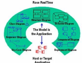
With Rational Rose RealTime, the development focus is always on graphical UML models, with a seamless information flow from specification to deployment as shown in Figure 14.
Use cases capture the requirements. Sequence diagrams elaborate on the message flow in the use case. Class and structure diagrams describe how to support the use cases. State diagrams describe the behavior of these classes, and in addition to containing the C or C++ the designer creates to specify the actions taken on state transitions, they can also include calls to legacy code or externally defined libraries. A developer can subsequently describe how to package the system for compilation and deployment.
Automatic Application Generation
All of this is in combination with a powerful UML compilation and visual execution environment for both hosts and targets. The UML model is semantically rich enough that, like a traditional programming language, it contains all of the information required for complete application code generation. The structure and state diagrams provide a visual representation of a large proportion of the overall application. For example, in very concurrent applications with large numbers of states, this could result in the automatic generation of up to 80% of the overall application code. The code that the designer creates (e.g., C or C++ code entered for state transitions) is emitted along with the previously mentioned automatically generated code.
This approach allows for substantial increases in designer productivity, and enables large improvements in software quality. Notably, the automatically generated code includes the structural framework of the system and its behavior. The manual coding of such parts is usually both a large exercise and the manual
translation from design to code is typically error-prone. Automatic code generation eliminates these problems and allows designers to focus their efforts on the actual design, not coding. At all stages of the development, the model is the source. This greatly enhances design integrity, as there is never a mismatch between the design and the implementation.
Model observation and debugging
Observability of the application at run-time on either host or target is also a key benefit of Rational® Rose RealTime. A UML model debugging environment allows developers to control and graphically observe the execution of the application on their workstations from within the tool in a full visual debug environment (with the ability to start/step/reset, probe, textually or visually trace, set breakpoints, etc.). Using this host execution environment, developers can prove out their designs and get early and concrete feedback on architectural and design decisions.
Additional support for distributed applications
Rational Rose RealTime integrates with Rational Connexis to support distributed system development. With Connexis, UML capsules can be flexibly deployed in various distribution schemes with minimal design changes. A run-time viewer provides the communication status and tracing essential to validate and debug distributed systems. Design patterns such as load sharing and overflow handling are provided to help developers create high-availability applications. Connexis optionally integrates with middleware to offer flexible network transport options (e.g., UDP/IP, TCP/IP, and non-IP networks). With Connexis, developers can focus their efforts on creating the application, not the distribution infrastructure.
An integrated suite solution
Rational Rose RealTime is the foundation of the Rational Suite DevelopmentStudio RealTime Edition, a pre-integrated UML tool suite. The suite contains Rational's market-leading development and testing tools, plus Rational Connexis to support distributed system development. The Rational Suite is designed to work with Rational ClearCase.
Identifying Capsules in Designs
can identify opportunities to exploit capsules in their designs, not just for modeling concurrency and distribution, but also as a general design aid.
The most obvious use of capsules is to model all elements of the problem domain and the design that are clearly or potentially concurrent or distributed.
Since they encapsulate both data and threads of execution, capsules should be used to resolve concurrency conflicts. For example, wherever there are shared resources capsules can be employed as their guardians. By virtue of their built-in mutual exclusion semantics, such guardians automatically protect these resources against concurrency conflicts.
In addition to the above general identification heuristics, the following sections detail other approaches to identifying and using capsules.
Use Case Approach
Use Cases are an approach to software development defined in the Rational Unified Process as described in [RUP]. In RUP, actors represent the users and any other systems, which may interact with the system being developed. Actors can also be used to capture internal components “acting” on other internal components (e.g., the software components using a major internal software component, such as a fault logging subsystem). Actors are a good way of representing the various concurrent stimuli that drive the overall embedded system and subsystems.
A use case represents how actors use the system, and corresponds to a potentially complex sequence of actions performed by the system to provide some high level capability, with observable results for the actors. For example, the steps involved in initiating and completing a two party telephone call can be expressed as a use case. In that example, the two parties are actors and the various alerting messages they receive are part of the use case. As the actors are often concurrent, the use cases themselves are often concurrent threads of execution the system must support. Thus the definition and analysis of use cases provides excellent insight into potential capsules.
Use case realizations describe the various classes used to support a use case and how the objects of such classes collaborate to perform the use cases. Use case realizations are important because they drive the design activities and prove traceability to the requirements (e.g., the use cases). For real-time embedded systems, use cases are often realized as a series of time-sequenced pair-wise exchanges of messages (i.e., message sequence charts). Actors and the objects implied by the use case are obvious candidates for capsules. They are often independent and thus need their own threads of control. Even if objects are not concurrent, they may have other characteristics that drive the need for them to be modeled as capsules. For example, objects with high requirements for response time may need to be managed by a dedicated capsule. Objects that could be intersected by use cases have the potential for race conditions, and thus can benefit from the thread encapsulation that capsules provide. Use cases are not only a valuable design aid for capsule selection but also help in capsule protocol definitions and state machine design.
Use cases benefit from an iterative approach. As use cases and their realizations are developed, the resultant capsules often spawn the need for more detailed use cases to explore their usage scenarios. This in turn can uncover the need for further capsules.
Architecture-Centric Approach
Use cases and their realizations are a valuable aid in capsule identification. However, this identification is best done in the context of an architecture that provides a foundation for how to construct and evolve the system. As architecture is typically the quintessential part of a system’s composition upon which all other parts of the system depend, it tends to contain the most important elements of the system. Architectures apply to more than individual systems. The architectures of large systems are recursively defined by the architectures of the smaller systems that they are composed of, and so on.
Capsules are an obvious and powerful technique for capturing architecture. The encapsulation provided by capsules allows developers to easily express abstractions or encapsulations of lower-level design concerns, and provides the required clean component decoupling required for partitioning teams for maximum parallel development. Most elements of architecture need to be strongly decoupled, are likely to be concurrent, and are often distributed. Casting elements of the architecture as capsules enhances the controllability of the system (i.e., the ability to start or restart various portions of the system). Message flow among capsules is a natural way of expressing how elements of an architecture work together. As with use cases, as more experience is gained with an architecture it is likely that iteration will be exploited to refine the architecture.
Execution-based capsule discovery and refinement
It is often difficult to pick the “right” capsules based solely on static analysis of the specification and paper-based design, especially in new systems where prior design experience can not be exploited. Compiling and running graphical UML models using Rational Rose RealTime provides an exceptional feedback mechanism to build up the required experience quickly and to help validate the choice of capsules. The process of building models does not have to be too prescriptive. For example, rather than going through a lengthy traditional analysis phase the developer can instead do a quick analysis to choose some hypothetical capsules. They would be subsequently validated and refined by the experience gained through execution feedback. For example, excessive message flow through numerous capsules for frequently executed use cases may imply potential performance issues. A less fine-grained capsule decomposition or a rethinking of the protocol definitions could address these issues.
Executable models are a relatively new concept for many developers. Such developers often fall into the trap of delaying execution because they equate models with paper or graphical designs that previously could not be run. In the past, the only running artifact was the completely developed program. With Rational Rose RealTime, models can and should be run as early as possible to gain the benefits of feedback. Developers need to recognize that to do such, models do not have to be fully complete. They just have to be complete enough and consistent among themselves to run. Using simplifying assumptions and abstractions enables early execution.
Other uses of Capsules
The previous sections have described some general approaches to capsule identification and usage. This section outlines additional specific uses of capsules that designers should consider.
Capsules can be used as representatives of external physical devices that are connected to the system since such physical entities are usually independent and thus inherently concurrent. An example is device driver capsules that serve to monitor and control the corresponding physical devices, and also to isolate the rest of the system from the specific implementation of the devices by providing an abstraction of the device. Such interface capsules (referred to as boundary objects in RUP) provide interface decoupling where future change is expected.
Capsules can model logical concurrency. Logical concurrency relates to conceptual concurrent “objects”, such as financial transactions or a telephone calls. They often represent overall use cases. As such use cases are often initiated by concurrent components (i.e., users of a system) it is likely that the threads of execution of these use cases are also concurrent. Modeling them as capsules provides useful control mechanisms. For example, a designer may need to temporarily hold back a particular telephone call to avoid a concurrency conflict or may need to abort it based on various failure scenarios. Since these conceptual objects need to be manipulated as a whole, it is convenient to represent them as capsules with interfaces that provide the appropriate functional capabilities.
Capsules can be used wherever complex coordination or sequencing of other capsules is required. Such coordination or control capsules bring each contained capsule into the desired operational state, maintain it
among entities (either one-to-many, or many-to-many), that may be best modeled using a separate class to model the interaction among the entities. For example, in telephone call processing each subscriber may be associated temporarily with any other subscriber in a call. A conference call may associate many subscribers in a highly dynamic relationship. A separate ‘call’ coordinator capsule can be used to model these dynamic interactions.
Passive Objects
From previous sections it is evident that capsules have wider applicability than just modeling concurrency. However, this does not mean that all objects in the design have to be modeled as capsules. Passive objects are a more appropriate choice where there is no need for an independent thread of execution. For example, entity classes in RUP model information that is long-lived and often persistent, but often does not need to initiate control actions. Purely functional objects (e.g., ones that process algorithms and typically have little or no state information) are best modeled as passive objects. If there are concerns about multiple threads of execution causing problems, such passive objects can always be encapsulated within capsules.
Consolidation and refinement of Capsules
Regardless of how capsules are identified and used, it is valuable to continuously review and improve capsule selection. During such iterations, the developer should consider the following consolidation and refinement questions.
Does each capsule have a clear well-defined responsibility or purpose, ideally expressed in a single sentence? If it is vague, then there may not be a strong rationale for the capsule existing.
Are some capsule purposes semantically identical or strongly similar, and thus indicative of redundant or overlapping capsules? This may indicate a missing abstraction, where commonality can be captured in a superclass, or a subset of responsibilities can be implemented by one or more component capsules which can be reused.
Is the purpose of a capsule too broad or does it handle too many purposes (e.g., is the term “and” used many times in the purpose description)? It may be a candidate for a composite capsule instead, with the multiple purposes handled by contained sub-capsules while the composite capsule is retained for abstraction purposes. Are the capsule responsibilities not strongly related to one another? Capsules should have a minimal number of clearly related responsibilities. If not, this indicates that the capsule is an aggregate that may need further decomposition. Capsules that do too much are often overly complicated and hard to maintain.
For both good design and potential reuse considerations, are most capsules relatively small and
self-contained? A capsule that is relatively small usually indicates simplicity and a well-defined purpose. It tends to be highly cohesive and is less likely to be affected by modifications to other aspects of the system. If it is defined autonomously (e.g., by a standalone purpose and function, defined by what it does and not what environment it is connected to) then it is much more likely to be reusable.
Is the purpose of the capsule too small or narrow, with little behavior? If it is too fine grained, should it be combined with another capsule? Capsules that do too little just add run-time overhead and make the overall model harder to understand.
Are the responsibilities of the capsule at a consistent level of abstraction? A mixture of very abstract and very low-level responsibilities may indicate that the capsule could be split up into multiple capsules. Is hierarchy employed appropriately to reduce the number of sub-capsules at any one containment level?
Summary
This paper describes how active objects can be used to address the challenges of real-time embedded software development, in particular the interaction problems that result from intersecting concurrent threads and the need to make objects easily distributable. Active objects address these problems by encapsulating not only data but also their own threads of execution, and by using highly encapsulated interfaces that isolate the
objects from their environment. Active objects can be mapped to operating system threads and processes, and can be expressed in UML as capsules using standard UML extensibility mechanisms. In addition to addressing concurrency and distribution, capsules are also a generally useful architecture and design aid. A variety of techniques can be used to identify, consolidate, and refine the definition of capsules. Capsule-based design is strongly supported by the Rational Rose RealTime tool.
References
[RRT] Rational Rose RealTime, http://www.rational.com
[RUP] P. Kruchten, The Rational Unified Process, Addison Wesley, 1998
[UML Guide] J.Rumbaugh, I. Jacobson, G. Booch, The Unified Modeling Language User Guide, Addison Wesley, 1999
[UML Ref] J.Rumbaugh, I. Jacobson, G. Booch, The Unified Modeling Language Reference Manual, Addison Wesley, 1999
About the Author
Garth Gullekson is the Rose RealTime evangelist for Rational Software Corporation. After graduating with an MS in Electrical Engineering, he worked for Nortel Networks for 14 years, designing and managing real-time telecommunications software for call processing, mulreal-timedia, and ATM applications. He is a co-author, with Bran Selic, of the book, "Real-Time Object-Oriented Modeling", and a contributor to the definition of UML. Garth co-founded ObjecTime Limited, whose ObjecTime toolset formed the real-time basis for Rational Rose RealTime.
Cupertino, CA 95014 Toll-free: 800.728.1212 Tel: 408.863.9900 Fax: 408.863.4120 Email: [email protected] Web site: www.rational.com
For International Offices: www.rational.com/worldwide
Rational, the Rational logo, the Rational e-development company, and Rational Rose RealTime are trademarks of Rational Software Corporation. References to other companies and their products use trademarks owned by the respective companies and are for reference purposes only.
Copyright 2000 by Rational Software Corporation.