Study on microstructure and mechanical properties of 304 stainless
steel joints by TIG-MIG hybrid welding
Emmanuel O. Ogundimu1, Esther T. Akinlabi1, and Mutiu F.Erinosho1*
1Department of Mechanical Engineering Science, University of Johannesburg, Auckland Park Kingsway Campus, Johannesburg, 2006, South Africa.
*Corresponding author: [email protected], [email protected]
Abstract
Stainless steel is a family of Fe-based alloys having excellent resistance to corrosion, and as such has been used imperatively for kitchen utensils, transportation, building constructions and much more. This paper presents the work conducted on the material characterizations of a TIG-MIG hybrid welded joint of type 304 austenitic stainless steel. The welding processes were conducted in three phases. The phases of welding employed are MIG welding using a current of 170A, TIG welding using the current of 190A, and a hybrid TIG-MIG welding with currents of 190/170A respectively. The MIG, TIG, and hybrid TIG-MIG weldments were characterized with incomplete penetration, full penetration and excess penetration of weld. Intergranular austenite was created towards the transition zone and the HAZ. The thickness of the delta ferrite (δ-Fe) formed in the microstructures of the TIG weld is more than the thickness emerged in the microstructures of MIG weld and hybrid TIG-MIG welds. A TIG-MIG hybrid weld of specimen welded at the currents of 190/170A has the highest UTS value and percentage elongation of 397.72 MPa and 35.7 %. The
TIG-MIG hybrid welding can be recommended for high-tech industrial applications such as nuclear, aircraft, food processing, and automobile industry.
Keywords: 304 austenitic stainless steel; MIG welding; TIG welding; Hybrid TIG-MIG weld;
Microhardness measurements; Microstructure; Tensile testing
1.0 INRODUCTION
Stainless steels are a class of materials, which are usually used for corrosion resistance applications, and however depending on their microstructural behaviour at room temperature, they are divided into different types as, ferrite, martensitic and precipitation hardening, duplex, and austenitic stainless steel. The most common type is the austenitic due to good welding characteristics, high corrosion resistance, non-magnetic nature and high formability [1-4]. The Type 304 austenitic stainless steels are largely believed to be weldable majorly by arc welding and resistance processes. The traditional arc welding is mostly delicate for industrial use due to the generation of coarse grains and inter-granular Cr-rich carbides nucleated along the grain boundaries in the heat affected zone (HAZ), which however weakens the mechanical properties of the joints [5-8].
Tungsten inert gas (TIG) welding process is used extensively in industries for welding stainless steel due to its higher quality weld, arc stability, smooth head appearances and less contamination in its weld zones. One of the prime advantages of this process of welding is attributed to the fact that the operating power can be controlled to an endurable minimum in order not to damage the material [9]. Although, the arc is sometimes influenced by electromagnetic forces and also thus, changes direction unexpectedly during welding. Therefore with these attributes, it will be difficult to obtain good and sound welded joints in such situations. In the same
vein, the penetration in TIG arc welding is relatively small and the welding process requires more set-up time which is not user-friendly. Instead, metal inert gas (MIG) welding is highly remarkable for industrial use due to high penetration and quickness in producing welds.
In MIG welding, a wire is allowed to pass through the welding gun at the same point as the inert gas. A range of materials with different thicknesses can also be welded using the MIG arc process [10]. However, the major drawbacks in MIG welding are less stable arc, burn-back, irregular wire feedback, more spark, and production of smoke and fumes respectively. In an experiment, a welding was conducted by substituting MIG arc welding process for the TIG process in order to weld a 6 mm thick joint in one pass only. After welding, undercut and humping defects were formed in the joint. Unsteady spatters and rough weld bead were also observed in the MIG welding than that used for the TIG process [11].
An experiment was conducted in order to characterize the effect of pulsed current on the weldment of a 3 mm thick of type-304 stainless steel plate using TIG welding. Welding current of 80-83 A and arc travel speed of 700-1230 mm/min were used. It was discovered that higher hardness values were observed in the HAZ of all the weldment due to grain refinement. Higher tensile strength was also found in the non-pulsed current weldment compared to the pulsed current weldment and the parent material [16]. A TIG welding was performed on AISI 304L stainless steel, and the weld bead profiles were compared for constant current and pulsed current setting. The effect of welding current on tensile strength, hardness profiles, microstructure and residual stress distribution of welding zone of the steel samples were reported to be improved. The tensile and hardness properties of the joints were enhanced as a result of the formation of finer grains and breaking of dendrites with the pulsed current used [12]. The influence of heat input on the microstructure and mechanical properties of gas tungsten arc welded 304 stainless steel joints was
revealed by different authors. The joints produced with low heat input showed higher ultimate tensile strength UTS than the samples welded with medium and high heat input. It was also discovered that, the average dendrite length and inter-dendritic spacing in the weld zone were increased with an increase in the heat input [13].
In another author’s research work, the microstructure and mechanical properties of a resistance upset butt welded joint of type-304 austenitic stainless steel were investigated. It was reported that the base material was preheated for 10 min at 1060oC and air cooled to reduce the cold work effects prior to the welding operation. In their result, it was concluded that an increase in the welding power caused the heat input to the weld joint area to increase and broadens the microstructural zones at the joint’s interface. However, high power was also revealed to be the most significant factor to decreasing the joint’s strength at hot spot [14].
A better way to improve and overcome these problems of TIG and MIG arc welding processes is by introducing a hybrid welding process of TIG and the MIG. With a TIG-MIG hybrid welding system, the cathodic spots of MIG arcs are noticeable for possible stable weld [15]. The influence of power input on a TIG-MIG hybrid welding of steel was monitored and reported to have a direct influence on the microstructural changes and the surrounding heat affected region of the joint. However, the power effect has created large thermally affected and heat penetrated areas [17, 18]. Consequently, this hybrid welding process has the prospect of becoming an innovative type of welding process since it synchronously merges the high efficiency of MIG with the high quality of TIG.
However, in this study, adequate welding conditions for type 304 austenitic stainless steel welding using TIG-MIG hybrid welding process will be investigated and thus controlled in order to determine the optimum condition for the process. 6 mm thick 304 stainless steel plates were
welded by TIG welding, MIG welding, and TIG-MIG hybrid welding respectively, thereby varying the current and voltage for the three weld operations. All the welded samples will be characterized through the microstructures, phase compositions, and mechanical properties.
2.0 EXPERIMENTAL PROCEDURES 2.1 Materials and process selection
Prior to welding, the preparation of 6 mm thick Austenitic stainless steel type-304 plates was achieved through cutting, polishing, and chemical cleaning. The steel plates with dimensions 175 mm × 100 mm × 6 mm were milled to 30o at the edge and maintained a root height of 1 mm on all the plates. For the welding process, two plates are brought together; thus forming V-groove. This allows filler submerge and a strong weld. The mechanical properties of both base and filler materials are listed in Table 1.
Insert Table 1 here
The TIG welding was done on TIG 200P DC/AC THERMAMAX while the MIG welding was carried out using a miller CP- 300 model MIG welding machine. An Argon gas was used to shield the process. A tungsten electrode with a diameter of 2.4 mm is fixed to the welding torch and the gas is allowed to flow through it. The diameters of the filler materials used for the TIG and the MIG welding are 2.4 mm and 1.2 mm respectively. Sample F2 denotes the joint plate welded by MIG welding; sample F4 represents the joint welds produced by TIG welding while sample F6 denotes the weld of TIG-MIG hybrid welding respectively. The surfaces of the plates were cleaned
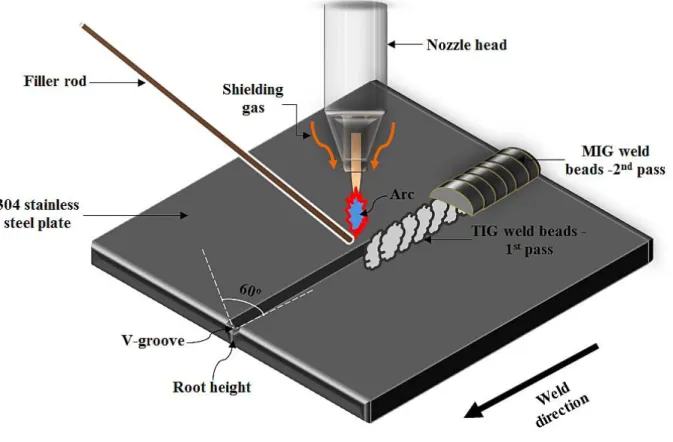
with acetone and dried off before welding in order to avoid any source of contamination that could creep into the weld metal. Figure 1 shows the schematic view of the TIG and MIG process.
Insert Figure 1 here
The TIG operation is the first (1st) pass that was carried out on the 304 stainless steel plate through the V-groove from the start of the notch to the end using the filler rod od diameter 2.4 mm. Then followed by the MIG operation (2nd pass) on the previously TIG welded beads using the filler diameter of 1.2 mm. The welding operation is shielded using Argon gas in order to protect the surface from oxidation.
The welding parameters used for these experiments are illustrated in Table 2.
Insert Table 2 here
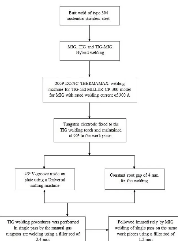
Figure 2 shows the method flow chart for the TIG-MIG welding process from the plate preparation to the final welding development.
Insert Figure 2 here
After the welding operation, specimens of dimension 20 mm x 20 mm x 6 mm were cut from each welded sample, and then prepared them for the metallographic analysis.
The mounted samples were subjected to microscopic examination after proper grinding and polishing processes. The microscopic examinations were conducted on the DP 25 Olympus Optical
Microscope and the TESCAN Scanning Electron Microscope (SEM) equipped with Oxford Instrument. The chemical composition of the welds was also investigated through the Energy Dispersive Spectroscopy (EDS). In order to study the mechanical properties of the samples, three transverse samples from the weld line perpendicular to the direction of the load application were cut from each welded plates using a water-jet cutter to obtain tensile specimen sizes in accordance to the standard ASTM E8/E8M-13a [19] as shown in Figure 3.
Insert Figure 3 here
An electro-mechanical tensile testing machine, Instron 5500R with a maximum load of 100 kN from the Mechanical Engineering Science laboratory, is used for the test. The setup is connected to a computer for parameter settings and retrieving of experimental data. The microhardness of different zones of the weldments was determined using a digital Vickers micro hardness tester. The indenter was pressed into the sample by an accurately controlled test load of 100 g and was maintained for a specific dwell time of 15 seconds according to ASTM E92-82 standard [20].
3.0 RESULTS INVESTIGATION 3.1 Sample visual inspection
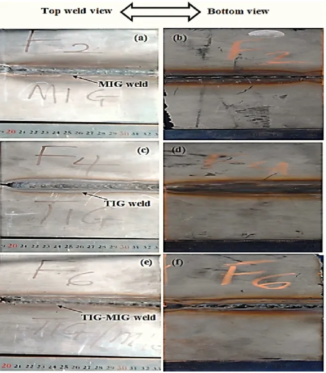
The physical appearances of the welded plates are shown in Figure 4. Figures 4 (a) to (f) show the top and bottom views of the MIG weld, TIG weld, and TIG-MIG hybrid weld respectively.
The weldment quality was observed at the top and bottom of the welded plates and there was no evidence of spatter and porosity from the welds. Table 3 summarizes the physical appearance and visual inspection/observation of the three welded samples.
Insert Table 3 here
The weld shape is narrow and the width of weldment is approximately 4 mm. The heat affected zones (HAZ)s are about 25 mm in all the welds. Sample F2 shows a significant trace of weld debris. Little traces of debris and excess penetration are observed in TIG-MIG weld of sample F6. However, the weld of the hybrid welding undergone complete penetration; and the droplet spreads better. The weld appearance and the shape of weld’s cross-section of sample F6 were improved evidently by the combination of TIG and MIG welding.
3.2 Microstructural evaluation
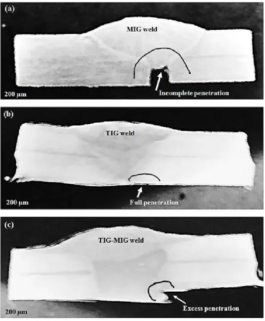
The microstructural examinations of samples F2, F4 and F6 were observed under the Optical microscope at low and high magnifications. Figures 5 (a) to (c) show the macrographs of the MIG weld, TIG weld and TIG-MIG hybrid weld of samples F2, F4 and F6 respectively.
Insert Figure 5 here
In order to have deep insight understanding of the durability of the metallurgical bonding formed during the welding process, the macrograph examination was carried out on the cross-sectional samples covering the multiple zones including the base metal, the HAZ, and the fusion zone from the weldment. The MIG weldment of sample F2 as shown in Figure 5 (a) exhibits an incomplete
penetration of weld in root gap. Samples F4 and F6 of TIG weldment and hybrid TIG-MIG weldment show full penetration of weld, however, sample F6 displays excess penetration due to the hybridized process of welding.
The microstructures of samples F2, F4 and F6 are observed at high magnifications under the optical microscope. Figures 6 (a) to (c) display the microstructures of the weld zones for MIG weld joint of sample F2, TIG weld joint of sample F4 and TIG-MIG hybrid weld joint of sample F6 respectively. However, there is no evidence of cracks and porosities observed.
Insert Figure 6 here
The microstructures of the weld zone are characterized with dendrites, and however, it was observed that as the welding current increases, the dendrite size and the inter-dendritic spacing in the weld metal also increase. The variation in the dendrite size can be attributed to the fact that at low welding current, the cooling rate is relatively faster due to the establishment of the steep thermal gradients in the weld metal, and which in turn allow lesser time for the dendrites to propagate. However, a higher heat input as a result of high welding current has led to the slow cooling rate and then provides ample time for the dendrites to propagate farther into the fusion zone. Similar behaviour was reported by Yan [6] and Kumar [13] when reporting the effect of heat input on the microstructure of gas tungsten arc welded AISI 304 stainless steel joints. The microstructural grains in the HAZ are much bigger than the weld zones due to the heat input distribution.
Figures 7 (a) to (c) show the SEM morphology of the heat affected zone for the MIG weld, TIG weld and TIG-MIG weld respectively.
Insert Figure 7 here
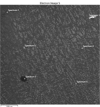
The microstructure of the MIG weld is characterized with coarse columnar dendrite of ferrite while the TIG has shown a thin and fine dendritic pattern of ferrite. The microstructures of the hybridized TIG-MIG weld are well nucleated and show some equiaxed ferrites after solidification within the weld zone. Intergranular austenite was also found developing towards the transition zone and the HAZ. Pearlite and allotriomorphic ferrite were not pronounced in the microstructures of all the weld samples. All the zones are composed of the delta ferrite (δ-Fe) dendritic structures in austenite matrix. The size of δ-Fe of the TIG weld of sample F4 is noticeably larger in thickness than the MIG weld and hybrid TIG-MIG weld of samples F2 and F6. Figure 8 shows the SEM-EDS electron image of sample F6 with point analyses from spectrum 1 to 6.
Insert Figure 8 here
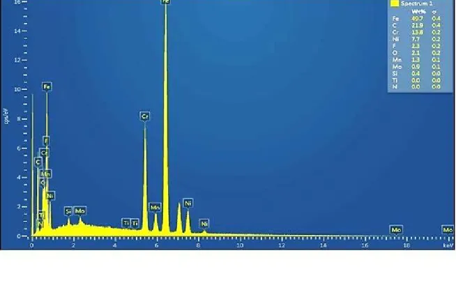
The EDS analysis was conducted on all the samples to analyze the chemical composition of the joint interface regions, and also to investigate the presence of intermetallic compounds formed in the welds. Figures 9 (a) and (b) show the EDS analyses of hybrid TIG-MIG weld of samples F6 welded using the current of 190/170A and welding speed of 4.5 mm/sec for the MIG weld and null welding speed for the TIG.
Insert Figure 9 here
From the results of the EDS spectra shown in Figures 9 (a) and (b), it was observed that iron (Fe) is the most prominent element in the composites with weight percent (wt %) between 45 wt % and
65 wt %; and depending on the region analysed. Chromium (Cr) is the second noticeable element in the composition and ranges between 12.4 wt % and 25 wt % approximately. Carbon (C) and Nickel (Ni) were also obvious in the weld with other traceable elements. The carbon element could be as a result of lack of proper shielding which in line introduces excess oxygen into the weld.
3.3 Tensile test outcome of weld specimen
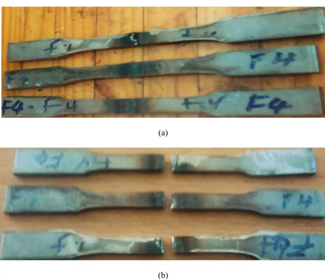
The physical appearances of the tensile specimens of sample F4 before and after testing are shown in Figures 10 (a) and (b). From each plate, three samples were cut for the tensile test for repeatable purpose.
Insert Figure 10 here
The tensile samples shown are for TIG welds of sample F4. From all indication, the entire deformed samples were fractured at the weld region. The summary of the tensile results is presented in Table 4.
Insert Table 4 here
The Ultimate Tensile Strength (UTS) of the nine welded specimens of MIG, TIG, and TIG-MIG welds are presented in the Table. From each plate, the repeated test specimens are designated as T1, T2, and T3 respectively. The UTS of the MIG weld of sample F2 varies between 590 MPa and
630 MPa while the UTS of TIG weld of sample F4 varies between 557 MPa and 630 MPa for the three repeated samples. The hybrid TIG-MIG weld of sample F6 gives the UTS between 611 MPa and 717 MPa respectively. The difference in the UTS of MIG weld and TIG weld is not that much. The variance in the UTS of TIG is attributed to the large HAZ exhibited at low travel speed. However, the combination of the interaction time and the heat input is high, and thus generate a slower cooling rate that allows the formation of large crystal structures within the weldment zone. The large grains formed from the crystals are actually responsible for the drop in the UTS and the yield strength of the TIG joint. The average UTS are taking into consideration for all the weld specimens. Figure 11 depicts the plot of the average UTS for the MIG weld, TIG weld, and hybrid TIG-MIG weld.
Insert Figure 11 here
The average UTS of the welded test samples vary from 584 MPa to 673 MPa. The welding parameters have a greater impact on the UTS developed. Among the three welded samples evaluated in this research work, sample F6 produced through hybridization of TIG and MIG welds at currents of 190/170A is characterized with the highest average UTS of 672.4 MPa while the lowest average UTS value of 584 MPa was evaluated for the TIG weld of sample F4 which was the welded at the current of 190A. The average UTS of sample F2 of MIG weld falls between the average UTS of other samples with a value of 607 MPa.
The UTS is important in selecting materials for most structural applications where high overloads are expected to occur and large amounts of energy must be absorbed. Figures 12 (a) to (c) depict
the stress-strain curve for the MIG weld, TIG weld and hybrid TIG-MIG welds as well as the stress against 0.2 % extension plotted on the same graph.
Insert Figure 12 here
The yield strengths of all the welded samples were relatively close to one another. The yield strength exhibited by MIG, TIG, and TIG-MIG welded samples are 372.59 MPa, 364.14 MPa, and 397.72 MPa respectively. From the results, the TIG-MIG weld of sample F6 unveils the highest yield strength. The percentage elongation was also evaluated for all the weld samples, thus the elongation values for the MIG, TIG and TIG-MIG welded samples are 19.6 %, 19.3 %, and 35.7 % respectively. The hybrid TIG-MIG welded sample has the highest strain hardening effect which exists between the strain of 10 and 80. The correlation between the UTS and percentage elongation is related to an increase in the ductility of the material. In another word, the percentage elongation is proportional to the UTS of the material. It can be deduced from the weld results that there is a small increase in the percentage elongation with a slight increase in the UTS of the welds. This behaviour can be attributed to the inhomogeneity in the microstructure of the joint’s interface of the welds produced due to the presence of intermetallic compounds [21]. The UTS of the base material was also characterized as shown in Table 4. The average UTS value of the base material is 685.33 MPa. This was established in order to calculate the weld joint efficiency. Equation 1 shows the weld joint efficiency used for the all the weld samples.
The welded joint efficiency varies from 100 % for a flawless weld down to 75 % for a tolerable weld. The weld joint efficiency produced for the MIG weld, TIG weld, and hybrid TIG-MIG welds are 88.57 %, 85.21 % and 98.11 % respectively. All the weld samples are of good quality; however, sample F6 of hybrid TIG-MIG weld exhibits the highest and excellent weld joint efficiency. The entire weld joints of MIG, TIG, and hybrid TIG-MIG have exceptional prospect since their weld joint efficiencies supersede the 75 % standard UTS of the base metal.
3.4 Hardness profiling
The hardness profiling of the MIG, TIG, and hybrid TIG-MIG welds are presented in this section. The hardness measurements were achieved horizontally across the weld zone.
Figure 13 shows the hardness profiling of samples F2, F4 and F6 of MIG, TIG and hybrid TIG-MIG welds respectively.
Insert Figure 13 here
The hardness values of the welded samples were measured from the left of the weld to the centre of the weld and to the right of the weld, thus maintaining a distance of 150 µm between indentations. There is an increase in the hardness values from the left towards the centre and then fall towards the right after attaining the peak values. From Figure 13, it can be deduced that there is a slight increase in hardness at the welded zone when compared with the HAZ and the base metal. The increase in the hardness value at the weld zone is attributed to the repeated thermal cycles experienced during welding procedure with the melting and solidification of the filler metal used. From the graph, it can also be discovered that almost all the samples experienced an increase in the hardness value in the welding zone than the base material. The hardness values of the weld
zone are in the range of 210 HV to 249.5 HV. Sample F6 of hybrid TIG-MIG weld exhibits the highest hardness value of 249.5 HV at the welds zone while sample F4 of TIG weld shows the lowest hardness value of 200 HV in the weld zone. The hardness has been proven to have a direct relationship with the strength of the welded joint.
4.0 CONCLUSIONS
From the study of the hybrid TIG-MIG welding of type 304 austenitic stainless steel, the following conclusions can be suggested:
TIG - MIG hybrid welding of stainless steel is possible with the excellent weld joint efficiency of 98.11 % achieved.
The weld’s surface finish of the TIG welds is better than that of the MIG welds.
Penetration of MIG welds is deeper than that of TIG welds but shows an incomplete permeation of the filler as observed at the root gap.
The weld strength or the tensile strength of the weld joint is dependent on the welding parameters like welding speed and welding current. However, hybrid TIG-MIG weld exhibits the highest average UTS of 672.39 MPa and also display the highest strain hardening effect among the other welded specimens.
Sample F6 of TIG-MIG hybrid welded at currents of 190/170A unveils the highest hardness value of 249.5 HV at the welds zone while sample F4 of TIG weld shows the lowest hardness value of 200 HV in the weld zone region. However, this result has indicated a direct correlation with the strength of the stainless steel’s welded joint.
[1] Feng, Y., Luo, Z., Liu, Z., Li, Y., Luo, Y., Huang, Y. (2015) Keyhole gas tungsten arc welding of AISI 316L stainless steel, Mater Des, vol. 85, pp. 24-31.
[2] Wu-Rong, W., Chang-Wei, H., Zhong-Hua, Z., Xi-cheng, W. (2011) The limit drawing ratio and formability prediction of advanced high strength dual-phase steels. Mater Des, vol. 32, pp. 3320-3327.
[3] Li, Z., Gobbi, S. (1997) Laser welding for lightweight structures. J. Mater. Process. Technol., vol. 70, pp. 137-144.
[4] Li, H., Sun, G., Li, G., Gong, Z., Liu, D., Li, Q. (2011) On twist springback in advanced high-strength steels. Mater Des, vol. 32, pp. 3272-3279.
[5] Lu, S., Fujii, H., Nogi, K., Sato, T. (2007) Effect of oxygen content in He–O2 shielding gas on weld shape in ultra-deep penetration TIG. Science and Technology of Welding & Joining, vol. 12, pp. 689-695.
[6] Yan, J., Gao, M., Zeng, X. (2010) Study on microstructure and mechanical properties of 304 stainless steel joints by TIG, laser and laser-TIG hybrid welding. Optics and Lasers in Engineering, vol. 48, pp. 512-517.
[7] Lima, A., Nascimento, A., Abreu, H., De Lima-Neto, P. (2005) Sensitization evaluation of the austenitic stainless steel AISI 304L, 316L, 321 and 347. J. Mater. Sci., vol. 40, pp. 139-144. [8] Muthupandi, V., Srinivasan, P. B., Seshadri, S., Sundaresan, S. (2003) Effect of weld metal chemistry and heat input on the structure and properties of duplex stainless steel welds. Materials Science and Engineering: A, vol. 358, pp. 9-16.
[9] Bagger, C., Olsen, F. O. (2005) Review of laser hybrid welding. Journal of Laser Applications. [10] Zhou, J., Tsai, H. (2008). Modeling of transport phenomena in hybrid laser-MIG keyhole welding. Int. J. Heat Mass Transfer, vol. 51, pp. 4353-4366.
[11] Meng, X., Qin, G., Zhang, Y., Fu, B., Zou, Z. (2014) High speed TIG–MAG hybrid arc welding of mild steel plate. J. Mater. Process. Technol., vol. 214, pp. 2417-2424.
[12] Karunakaran, N., Balasubramanian, V. (2011) Effect of pulsed current on temperature distribution, weld bead profiles and characteristics of gas tungsten arc welded aluminum alloy joints. Transactions of Nonferrous Metals Society of China, vol. 21, pp. 278-286.
[13] Kumar, S., Shahi, A. (2011) Effect of heat input on the microstructure and mechanical properties of gas tungsten arc welded AISI 304 stainless steel joints. Mater Des, vol. 32, pp. 3617-3623.
[14] Sharifitabar, M., Halvaee, A., Khorshahian, S. (2011)Microstructure and mechanical properties of resistance upset butt welded 304 austenitic stainless steel joints. Mater Des, vol. 32, pp. 3854-3864.
[15] Kim, T., Suga, Y., Koike, T. (2003) Welding of thin steel plates by hybrid welding process combined TIG arc with YAG laser. JSME International Journal Series A Solid Mechanics and Material Engineering, vol. 46, pp. 202-207.
[16] Raveendra, A., Kumar, B. (2013) Experimental study on Pulsed and Non-Pulsed Current TIG Welding of Stainless Steel sheet (SS304). International Journal of Innovative Research in Science, Engineering and Technology, vol. 2.
[17] Olabi, A., Hashmi, M. (1996) The microstructure and mechanical properties of low carbon steel welded components after the application of PWHTs. J. Mater. Process. Technol., vol. 56, pp. 88-97.
[18] Shehata, F. (1994) Effect of plate thickness on mechanical properties of steel arc welded joints. Mater Des, vol. 15, pp. 105-110.
[19] Standard, E8/E8M, (2009) Standard Test Methods for Tension Testing of Metallic Materials, ASTM International, West Conshohocken PA; 2009.Doi: 10.1520.
[20] ASTM E92-82, (1982) Standard Test Method for Vickers Hardness of Metallic Materials. [21] Blight, G. (2009) Geotechnical Engineering for Mine Waste Storage Facilities. CRC Press.
Figure 4: (a, b) – Top and bottom views of MIG weldment of sample F2; (c, d) – Top and
bottom views of TIG weldment of sample F4; (e; f) – Top and bottom views of TIG-MIG weldment of sample F6
Figure 5: Macrographs of the welded joints (a) MIG weldment of sample F2; (b) TIG weldment
of sample F4; (c) hybrid TIG-MIG weldment of sample F6
Figure 6: Microstructures of the weld zones (a) For MIG weld joint of sample F2; (b) TIG weld
joint of sample F4; (c) TIG-MIG hybrid weld joint of sample F6.
(a)
(c)
Figure 7: Microstructures of the heat affected zone (a) For MIG weld joint of sample F2; (b)
TIG weld joint of sample F4; (c) TIG-MIG hybrid weld joint of sample F6.
Figure 8: SEM-EDS image of hybrid TIG-MIG welds of sample F6
(a)
(b)
Figure 9: EDS analyses of sample F6 of hybrid TIG-MIG welds (a) spectra 1, (b) spectra 4
(a)
(b)
Figure 13: Hardness profiling of the weld’s samples
LIST OF TABLES
Table 1: Chemical composition (wt. %) of the base metal and filler used
Alloys Element C Si Mn P S Cr Ni Fe Base material (304) 0.03 0.75 2.00 0.045 0.03 19.50 12 Bal. Filler material (316) 0.03 0.65 2.50 0.03 0.03 18-20 11-14 Bal.
Table 2: Welding parameters for the experiment Parameters
Sample F2 Sample F4 Sample F6
MIG TIG TIG MIG
Current (A) 170 190 190 170
Voltage (V) 21 23 23 21
Arc force (%) 30 N/A 30 N/A
Pre-flow Time (s) 0.1 0.1 0.1 0.1
After- flow Time (s) 6 6 6 6
Basic Current (%) 50 50 50 50
Wire feeding speed (mm/s) 4.5 N/A N/A 4.5
Gas flow rate (l/min) 20 20 20 20
Welding speed (mm/s) 4.8 2.15 2.15 4.8
Filler material diameter (mm)
Table 3: Summary of surface’s visual inspection
Weld Properties Sample F2 Sample F4 Sample F6
Improper fluxing No trace No trace No trace
Cracking No trace No trace No trace
Slag Inclusions No trace No trace No trace
Undercutting No trace No trace No trace
Excess Penetration No trace No trace Little trace
Incomplete penetration No trace No trace No trace
Porosity No trace No trace No trace
Welding debris Significant trace No trace Little trace
Table 4: Tensile behaviour of MIG, TIG and hybrid TIG-MIG welds
Specimen Welding Current (A) Welding Voltage (V) Welding Speed (mm/s)
Ultimate Tensile Strength (MPa) T1 T2 T3 F2 170 25 4.5 629.43 590.64 600.03 F4 190 23 N/A 629.07 557.79 564.83 F6 190/170 23/25 4.5 689.16 611.81 716.22 Base metal 640 673 743