High-Resolution Tactile Sensor Using the Movement of a Reflected Image
Satoshi Saga∗ Univ. of Tokyo Takeshi Morooka† Univ. of Tokyo Hiroyuki Kajimoto‡ Univ. of Tokyo Susumu Tachi§ Univ. of Tokyo ABSTRACTIn recent years, many tactile sensors have been developed with the advancement in robotics. For example, there are sensors that mea-sure the contact state or force distribution. They are very useful, but the resolution of the measurement is still inferior as compared to that of a human. Thus, we propose a new type of optical tactile sensor that can detect surface deformation with high precision by using the principle of optical lever. We construct a tactile sensor that utilizes the resolution of a camera to the maximum by using transparent silicone rubber as a deformable mirror surface and tak-ing advantage of the reflection image.
Keywords: tactile sensor, optical lever, reflected image, transpar-ent silicone
1 INTRODUCTION
In recent years, with the advancement in robotics, many tactile sen-sors have been developed. Several tactile sensen-sors are available in the market: some of them include a force sensor with 6 degrees of freedom that can measure the force at one point. Another sen-sor can measure the distribution of the contact state or one that can measure the force distribution [1].
The disadvantage of these distribution–type force sensors is that the number of sensor units with dense of wiring is excessive. Each sensor unit is arranged in close proximity to the measurement sur-face in order to allow a small sensor to be individually distributed, and the wiring that gathers information from a unit is also individu-ally wired. Therefore, a sensor itself cannot avoid deterioration due to the stress of repeated measurement; further, the assembly of the wiring is complicated.
Some optical sensors [9, 4] such as the distribution–type optical tactile sensor exist at the study level. They provide fine examples by the use of which a unit and the corresponding wiring can be elimi-nated from the measurement surface by using a camera as an optical sensor. However, as it measures the motion of markers that are em-bedded in the elastic body, the sensor resolution is determined by the markers, and not by the resolution of the camera. Therefore, it does not fully utilize the resolution of the camera.
On the other hand, several techniques, which have not been so far used for tactile sensors, to measure the shape of an object have been studied. For example, there is a method that uses a moire in-terference fringe pattern or slit light when the object is a dispersion surface [2, 6]. In addition, there is an exact measurement method that uses a laser and a collimator [3]. One method uses the specular surface of water [7]. However, in these methods, it is difficult to improve the resolution of time, hence; these techniques are limited to static objects.
∗e-mail: [email protected]
†e-mail: [email protected] ‡e-mail: [email protected] §e-mail: [email protected]
Thus, we examine a sensor that uses an optical lever. An optical lever is a technique that magnifies the displacement by using the characteristic of reflection. The optical lever technique is mostly used in minute domains, like sample measurements under a micro-scope. In addition, the deformation of a glass surface was measured in the study [5]. The object measured in this technique is static glass surface and it premises a recursive calculation. Moreover, this ap-proach measures the deformation of the glass surface itself and does not measure the contact object. We proposed a sensor with a new system that takes advantage of an optical lever, and measures a re-flection image in order to use the resolution of a camera; further, the viewpoint of the tactile sensor measured the contact object. In other words, we construct a tactile sensor by placing an optical lever and a flexible mirror surface together, and use this combination.
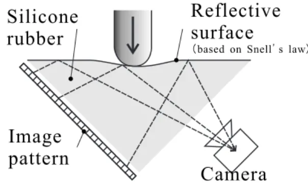
Transparent silicone rubber is used as the flexible mirror surface. Because of the use of silicone rubber and the distribution of the re-fractive index at the air interface, the boundary surface has a reflec-tion characteristic similar to that of a mirror surface. We construct a sensor with a flexible mirror surface by using this mirror surface reflection characteristic (figure 1).
Figure 1: Section of a sensor
2 PRINCIPLES
In our sensor, the optical lever plays an important role. The aim is to develop a flexible mirror surface in order to realize this optical lever. We can acquire a reflection image in a mirror surface by using the above mentioned properties and obtain the deformation of the mirror surface in itself using geometrical optics by measuring the displacement. Further, we explain each of these elements in detail. 2.1 A Reflection Condition
The optical lever technique is mostly used in minute domains, like sample measurements under a microscope. By irradiating the tip of cantilevers with lasers and using the characteristic of reflection, an optical lever is used to magnify the displacement of a reflection surface. In addition, the deformation of glass surface was measured in the study [5].
Transparent silicone rubber is used as the flexible mirror surface. With regard to the boundary between silicone rubber and air (figure 2), the refractive indexes are denoted by ns and na, respectively,
and the refraction angles byφs andφa, respectively. Further, the
incidence angle is indicated. When the distribution of the refractive index at the boundary of silicone rubber and air satisfies equation 3, total reflection occurs; further, this boundary surface assumes the reflection characteristic of a mirror surface. We construct a sensor with a flexible mirror surface by using the above mentioned mirror surface reflection characteristic.
Figure 2: Snell’s law
nssinφs = nasinφa (1) φs = arcsin( na ns sinφa) (2) > arcsin(na ns ) (3)
2.2 Deformation of the Reflection Image
In some optical tactile sensors, a camera is used as an optical sensor [4]; the sensor obtains the deformation by tracing a marker. How-ever, the resolution of this sensor is limited because of the resolu-tion of the marker. We propose a tactile sensor for the new system that uses a reflection image in order to use the resolution of the camera to the maximum possible extent. We employ it as a tactile sensor by combining an optical lever and a flexible mirror surface. By arranging the image pattern, camera and the transparent silicone rubber similar to the arrangement in figure 1, light dispersed from the image pattern is reflected from the silicone rubber boundary to the camera. If the contact object touches the silicone rubber, the silicone rubber boundary will be deformed. The reflection surface results in deformation, and the reflection image of the image pattern is deformed. We measure the deformation of the reflection surface itself by solving an inverse problem using this deformation. There-fore, the entire reflection image contains information; as a result, the resolution of the camera can be utilized to the maximum extent. However, we only use the characteristic point of the captured image in this study, we can use all the points in the captured image in the form of information for reconstruction.
2.3 Geometrical Optics
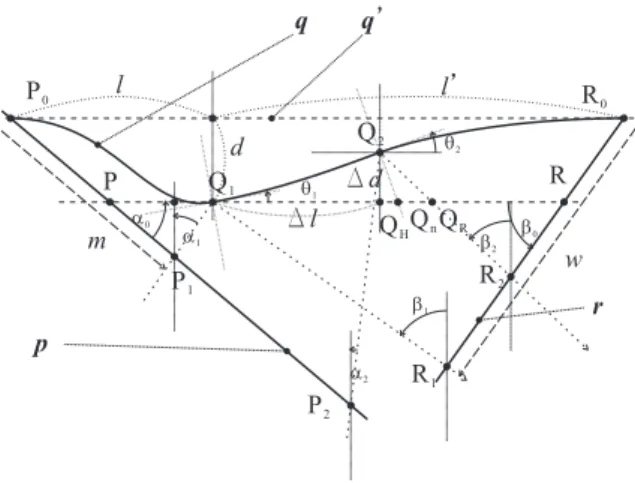
When the captured pattern is arranged as a planar as shown in figure 3, the surface with this pattern is referred to as a pattern surface p. The angle between the pattern surface p and the reflection surface
q is represented byα0, and the angle between the captured surface
r and reflection surface q byβ0.
We define the angle at each point on the reflection surface q as θ. We assume that after some deformation Q1, which is at a dis-tance l from P0, is projected at a distance d and inclined to the angleθ1with respect to the surface q0before deformation. Simi-larly, after the deformation Q2, which is at a distance of l+∆l from P0, is projected at a distance d+∆d and inclined to an angleθ2.
Figure 3: Geometrical optics
Figure 4: Geometrical Optics (Part)
Further, we assume that an image is formed when P1→Q1→R1
and P2→Q2→R2; the ray group captured by the camera is as-sumed to incline to the pattern surface at anglesβ1andβ2 and at anglesα1andα2to the captured surface. If the degree of leaning of the reflection surface in Q1and Q2changes continually similar toθ1→θ2,∆θ, height displacement∆d and the length of Q2QH
can be expressed as follows: ∆d = Z∆l 0 tan(θ+∆θ ∆ll)dl (4) = ∆l ∆θlog(| cosθ cos(θ+∆θ)|) (5) In addition, based on the symmetry of an incidence angle and the reflection angle on the reflection surface, the following eqations are obtained: 6 P 2Q2QH = 6 QHQ2QR−26 QHQ2Qn (6) = β2−2θ2 (7) α2 = β2−2θ2 (8) Similarly, α1=β1−2θ1 (9)
Next, we express m=P0P1,w=R0R1 with l. Based on the sine theorem at4P0P1Q1in figure 4, we get
γ=arctand l (10) √ l2+d2 sin(π2−(α0−α1)) = m sin(π2−(α1−γ)) (11)
m=pl2+d2 cos(α1−γ) cos(α1−α0) (12) Similarly, we get γ0=arctand l0 (13) w=pl02+d2cos(β1−γ 0) cos(β1−β0) (14) 2.4 Reconstruction of the reflection surface
We can measure m,w,β1andβ2using our sensor; L0,α0andβ0are known. The quantity required is the distribution ofθ and d. We can construct∆d if∆θand∆l are known from equation 5; further,
we can reconstructθ and d if∆θ,∆d are known. In this case, the
expressions 12 and 14 cannot be solved for unknown values ofθ→ θ+∆θ,l→l+∆l since there are only a few equations, however,
in this situation it is not solved for a number to be unknown as θ→θ+∆θ,l→l+∆l in expression 12,14 because there are a few
equations. Here, we define
∆α≡α1−α0 (15)
From the equation 12, we get
m2cos2∆α−(l2+d2)(cos2(α0+∆α)) =0 (16) When∆αis expressed asγ=0,∆α'0 from the second Taylor series expansion, equation 14 can be expressed as follows:
∆α= −(d2+l2)cosα0sinα0 ± v u u u t (d2+l2)2cos2α 0sin2α0 −(m2−(d2+l2)cos2α0) ×((−m2) + (d2+l2)(cos2α0−sin2α0)) (−m2) + (d2+l2)(cos2α 0−sin 2α 0) (17)
From the equations 9,15 and 17 we can expressθ1with the known parameters and measured values.
By defining Q1in equation 5 as the nthcharacteristic point, and defining∆d as∆dn, from the continuation property of a boundary
surface, we assume
∆dn'∆dn+1 (18)
Based on this, we can express equation 5 as follows: ∆dn+1= ∆ln
∆θn
log(| cosθn cos(θn+∆θn)
|) (19)
Since we assume d=0 at l=0 and l=L0, we get lnandθnfrom
equation 12. We obtain∆θnfrom the given value ofθnand calculate
∆dn+1equation 19. We getαn,dn, and the distribution ofαand d
by iterating this calculation step-by-step.
3 SIMULATION
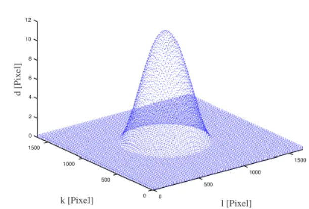
Based on the geometrical optics elaborated in the above mentioned paragraph, we confirm the precision by using a simulation. This sensor has 1637 [pixel] square size and deformed size in vertical direction is 13 [pixel] (figures 5 and 10).
l [Pixel] k [Pixel] d [Pixel]
Figure 5: Smooth deformation
3.1 Smooth Surface
We assume a curved surface (upside down), as shown in figure 5, as the reflecting surface and assume thatβ1=β2=β0, L0=1637and α0=β0=
π
4; the camera center is placed at infinity.
We calculate the point Rn(n=0...N)where the disintegration
point on the pattern surface Pn(n=0...N)is reflected onto the
cap-tured surface by the reflection surface. In this manner, by calcu-lating Pnand Rnand the equation 19, we solve an inverse problem
and obtain the angle distributionθnand depth distribution dnas an
approximate distribution of d can be traced almost precisely.
Figure 6: Simulation result ofθ
We examine an error in the true value in detail. Figure 8 shows the error distribution ofθ, and figure 9 shows the error distribution of d. An error rate (the error/truth value) is suppressed to approxi-mately 1% in the entire area.
The value at l=0 is near the true value in the series of rises, and
l=L0is near the true value in the series of drops.
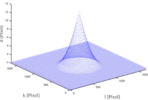
3.2 Needle-Shaped Surface
We assume a needle-shaped surface with an upside-down shape, as shown in figure 10, as the reflecting surface; further,β1=β2=β0,
L0=1637 andα0=β0= π
4; the camera center is assumed to be at infinity. The calculation results are shown in figures 11 and 12.
A solid line represents the shape of the original reflection sur-face;−represents the result of the summation of∆l and∆d from l=0 in a series of rises. 4is the result of the summation from
Figure 7: Simulation result of depth
Figure 8: Simulation error result ofθ
Figure 9: Simulation error result of depth
l [Pixel] k [Pixel] d [Pixel]
Figure 10: Needle-shaped deformation
l=L0in a series of drops, and°is average of−and4. It can be observed that the distribution of d can be traced almost precicely.
Figure 11: Simulation result ofθ
We examine the error in the true value in detail. Figure 13 shows the error distribution ofθ, and figure 14 shows the error distribution of d. An error rate (the error/truth value) is suppressed to approx-imately 1% in the entire area. The value of l=0 is near the true value in the series of rises, and l=L0is near to the true value in the series of drops.
In addition, in comparison with the result of the smoothly curved surface, significant difference is not observed. In other words, this shows that our sensor can measure the shape without any problem even if differentiation is impossible in the plane of reflection.
4 MOUNTING
Based on the simulation in the above mentioned paragraph, we build a real system. By using an implemented sensor, we measure the real tranformation in a real environment.
4.1 Silicone Rubber with Image Pattern
We use the addition-polymerization-type silicone rubber (KE109A,B[8]). We prepare a triangular pole-shaped flask with transparent acryl and pour silicone rubber into it and perform a lap reaction. After lap reaction, we exfoliate with one acryl board and make a sensor surface. One of the left acryl surfaces become a pattern surface and another one become a captured surface. In this case we use a lattice-patterned paper as a pattern surface. In
Figure 12: Simulation result of depth
Figure 13: Simulation error result ofθ
Figure 14: Simulation error result of depth
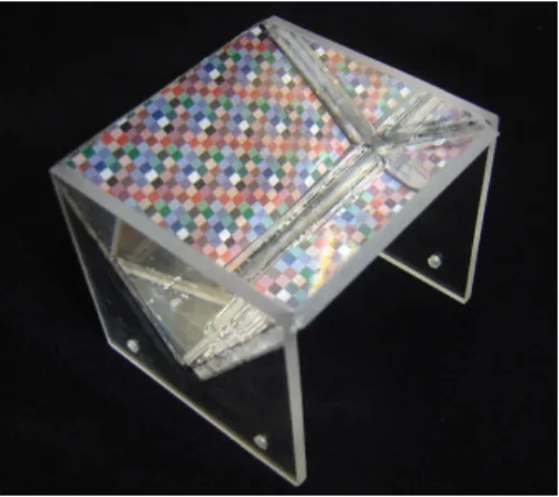
this manner, we prepare a sensor having a flexible mirror surface (figure 15). We install a camera to capture the flexible mirror
Figure 15: Silicone rubber with a lattice pattern
surface adequately and fix it (figure 16).
Figure 16: Overview of the sensor
5 EXPERIMENT
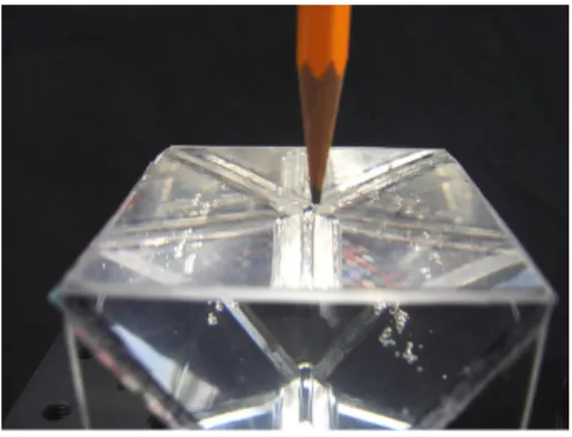
With the implemented sensor, we measure the real tranformation in a real environment. In this case, we place the tip of a pencil on the sensor face (figure 17) and measure the status when we push it down by about 0.2 [mm].
We show the acquired image before and after the deformation in figures 18 and 19. Here we use a lattice pattern as the image pattern. We took association between one line of central vertical lattice points of two pieces of images. By using the equations 9,15 and 17 a shape is reconstructed.
Figure 20 shows the series of rises and the series of drops. The scale of the image is 1 [pixel]'0.1 [mm] because the acquired image size is 625×392 [pixel], the lattice pattern has a width of 2.5 [mm] width, and there is 16 pieces of lattice in vertical orientation in the image. Then, the peak value in figure 20 is almost near the true value. An error rate (the error/truth value) is suppressed to approximately 10% at the peak area. The value of l=0 is near the true value in the series of rises, and l=L0is near the true value in the series of drops. The solution of increasing accuracy is considerd as future work.
Figure 17: Deformation overview
Sampling point for reconstruction
Figure 18: Before deformation
Sampling point for reconstruction
Figure 19: After deformation
Figure 20: Result of depth
6 CONCLUSION
In this paper, we proposed a tactile sensor that employs a new method that utilizes the principle of optical lever and a flexible re-flection surface. We constructed a tactile sensor that took advan-tage of the reflection image whose deformation was detected with high precision using an optical lever; the sensor also took sufficient advantage the resolution of a camera by using transparent silicone rubber as a flexible mirror surface.
Through a simulation, we showed that the reconstruction of a plane of reflection from an image was possible. The reconstrucion is carried out by using geometrical optics and by an appropriate approximation in the constituted tactile sensor. In addition, we ac-tually produced a prototype made of silicone rubber and showed that shape restoration of a plane of reflection was possible.
Our proposed technique combines the optical lever and a flexi-ble surface of reflection. Therefore, the modification of a pattern surface and a captured surface according to the measuring object is possible. In other words, we can arrange a laser, light emmision diode (LED), or liquid crystal display (LCD) on the pattern surface and a camera or photo detector (PD) on the captured surface. In the future, we wish to examine these combinations, in particular, dynamic pattern generation using a liquid crystal display.
REFERENCES
[1] Nitta Corporation. Flexi force.
http://www.nitta.co.jp/product/mechasen/sensor/ tactile_top.html.
[2] Miike Hidetoshi, Koga Kazutoshi, Yamada Takehito, Kawamura Tat-suji, Masaaki Kitou, and Takikawa Naoshisa. Measuring surface shape from specular reflection image sequence - quantitative evaluation of surface defects of plastic moldings. Japanese Journal of Applied Physics, Part 2, 34(12A):L1625–L1628, Dec 1995.
[3] Yamaguchi Ichirou, Yamamoto Akihiro, and Yano Masaru. Surface to-bography by wavelength scanning interferometry. Optical Engineering, 39(1):40–46, Aug 1999.
[4] Kazuto Kamiyama, Kevin Vlack, Hiroyuki Kajimoto, Naoki Kawakami, and Susumu Tachi. Vision-Based Sensor for Real-Time Measuring of Surface Traction Fields. IEEE Computer Graphics &
Applications Magazine, pages 68–75, 2005.
[5] J¨urgen H. Massig. Deformation measurement on specular surfaces by simple means. Optical Engineering, 40(10):2315–2318, October 2001. [6] Baba Mitsuru, Konishi Tadataka, and Handa Hisashi. Shape measure-ment of columnar objects with specular surfaces by slit ray projection method. Systems and Computers in Japan, 33(4):50–60, April 2002. [7] Howard J. Schultz. Specular surface stereo: a new method for retrieving
the shape of a water surface. Proceedings of SPIE - The International
Society for Optical Engineering, 1749:283–294, 1992.
[8] Shin-Etsu Chemical Co., Ltd. 2 liquid type RTV rubber KE109. [9] Kouichi Yamada, Kenji Goto, Yoshiki Nakajima, Nobuyoshi Koshida,
and Hiroyuki Shinoda. A sensor skin using wire-free tactile sensing elements based on optical connection. In SICE 2002. Proceedings of the
41st SICE Annual Conference. Soc. Instrument & Control Eng. (SICE),