Semi-Automated Part-Task Trainer Prototype Development Environment
Rusty Kinnicut and Dick Stottler
Contract Number N68335-98-C-0147
Topic Number: N98-059
Topic Title: Interactive Part-Task Training over Local Area networks (LANS) and the Internet"
Technical POC: Naval Air Systems Command HQ Attn: William Walker, PMA2052C
Bldg. 2272 - Suite 345 47123 Buse Road Unit IPT Patuxent River, MD 20670-1547
Final Progress Report
January 20,1999
DISTRIBUTION STATEMENT A: Approved for public release; distribution is unlimited
Stottler Henke Associates, Inc. (SHAI) 1660 So. Amphlett Blvd., Suite 350
Semi-Automated Part-Task Trainer
Prototype Development Environment
Abstract
In this Phase I SBIR research, we proved the feasibility of a semi-automated part-task
trainer (PTT) prototype development environment. In this effort, we set out to address
the shortfalls of traditional PTTs and to introduce new concepts into the PTT prototyping
process. The research developed innovative rapid prototyping techniques for the
development of PTT prototypes. These techniques are leveraged upon the state-of-the-art
software engineering methodologies of component oriented programming (COP),
distributed objects, and visual development environments. This means our environment
will maximize software reuse and support a number of COTS tools. This innovation will
result in a dramatically reduced cost of PTT prototype development and maintenance.
Further, prototypes built with this system will employ intelligent tutoring systems (ITSs)
which tailor training programs based on detailed mental models of the students.
Techniques for defining ITSs using the COP paradigm were designed during this project.
Finally, the prototyping environment enables the development of PTTs which take full
advantage of intranets and the Internet. This enables features such as distributed
simulations, team training, and student monitoring utilities to be integrated into PTT
prototypes. A proof-of-concept prototype was developed to demonstrate the key concepts
and a full operational system was designed.
Semi-Automated Part-Task Trainer
Prototype Development Environment
Final Report
1. INTRODUCTION 2
1.1 PHASE I OBJECTIVES 3
2. PHASE I INVESTIGATION 4
2.1 CURRENT PART-TASK TRAINERS 4
2.2 RAPID PROTOTYPING TECHNOLOGY SURVEY 6
2.3 INTELLIGENT TUTORING SYSTEMS AND PART-TASK TRAINING 8
2.4 PROOF-OF-CONCEPT PROTOTYPE 9
2.5 PHASE II SYSTEM DESIGN 10
3. PHASE I PROTOTYPE 11
3.1 NAVIGATIONAL PROCEDURES OF AH-1WCDNU 11
3.2 PROOF-OF-CONCEPT RAPID PROTOTYPING 11
3.3 DISTRIBUTED ARCHITECTURE 13
3.4 INTELLIGENT TUTORING SYSTEM 14
3.5 SIMULATION ENVIRONMENT 17
3.6 INSTRUCTOR UTILITY : 18
4. PHASE II SYSTEM DESIGN 18
4.1 OPERATIONAL TRAINER-PDE PROTOTYPE 18
4.2 TRAINER-PDE SYSTEM OVERVIEW 19
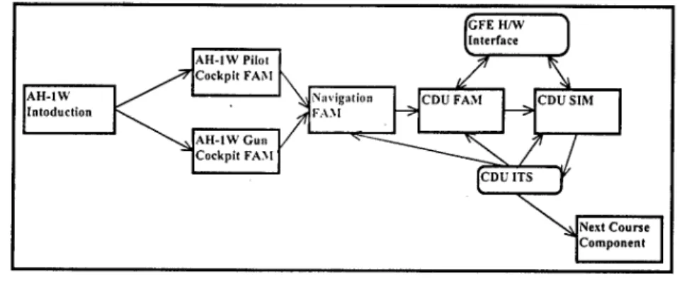
4.2.1 Components 20 4.2.2 Palettes 20 4.2.3 Event Model 21 4.2.4 Property Editors 21 4.2.5 ITS Architecture Template and Development Roadmaps 22
4.3 PHASE II SYSTEM ARCHITECTURE 22
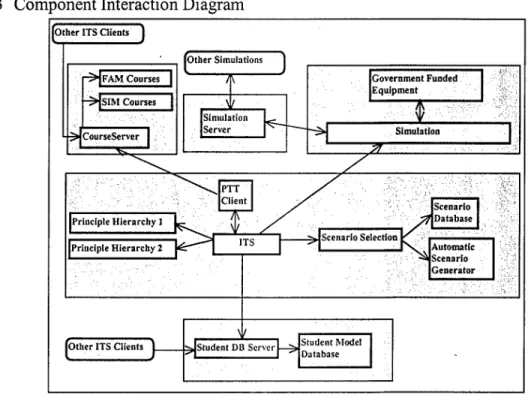
4.3.1 Platform Specification 22 4.3.2 Development Environment 22 4.3.3 Component Interaction Diagram 23
4.4 TRAINER-PDE SOFTWARE COMPONENTS 24
4.5 PHASE II SYSTEM DESIGN SUMMARY 27
5. FUTURE WORK & COMMERCIALIZATION 27
5.1 PHASE II TECHNICAL OBJECTIVES 27
5.1.1 Improve Efficiency ofPTT Development and Effectiveness of Resulting PTT. 28
Stottler Henke Associates, Inc. N98-059: Final Report
1. Introduction
The need of the armed forces to maintain effective readiness at a low cost is as necessary as ever. Part-task training plays a crucial role in maintaining this readiness. The more resources these part-task trainers can make use of and the more realistic the simulation environment they provide, the more effective the part-task trainer will be. The ideal part-task trainer will make efficient use of state-of-the-art concepts to attain these goals. This is where current part-task trainers typically fall short. Most part-task trainers are built in a machine-dependent manner for platforms which can't effectively fulfill the demand placed on them by the part-task trainer. This machine dependence deprives the part-task trainers of forward compatibility and portability. Forward compatibility and portability are properties which would enable part-task trainers to gracefully evolve with technological advancements. Machine dependence also insures expensive part-task trainer maintenance cost when modifications are made to a training program. That is, when the task being trained is even slightly modified, the cost of supporting the changes within the part-task trainer is very high. Further, current part-task trainers fail to take efficient
advantage of the networked computing environments which prevail today. When current part- task trainers make use of computer networks, they typically ignore security issues. The final shortfall of traditional part-task trainers is their failure to employ some of the powerful concepts developed by computer-based training researchers in recent years.
What is needed is a robust part-task trainer prototyping environment which effectively addresses all of the above concerns. If this environment makes proficient use of an industry proven component model, a standard distributed object model, and a robust portable
programming language, then the issues stemming from machine dependence will have been effectively addressed. The environment can be visually driven and distributed over a local area network (LAN) or a wide area network (WAN) securely. The environment will be sufficiently general and extensible, thus supporting the easy integration of many value-added enhancements. Finally, the integration of a number of computer-based training methods will enable the resultant part-task trainers to tackle new classes of training tasks not previously considered for part-task training.
The Phase I research set out to address the concerns with current part-task trainers and to develop a new concept for part-task trainer prototyping. The new concept for part-task trainer development is the Semi-Automated Part-Task Trainer Prototyping Environment, Trainer-PDE. Trainer-PDE leverages the use of emerging, industry proven technologies, from the object oriented community to facilitate the rapid prototyping of part-task trainers. These industry proven technologies allow for Trainer-PDE to make efficient use of relatively low-cost Commercial-Off-The-Shelf (COTS) software, reusable software components, and open standards. Additionally, support for Intelligent Tutoring Systems (ITS) which cater training programs to individual students, plays a significant role in the Trainer-PDE concept. Intelligent tutoring systems enable the part-task trainer to tackle more cognitive training tasks than the traditional part-task trainer. Intelligent tutoring systems can also often make up for shortfalls in the realism of low fidelity simulation environments. The Trainer-PDE system will result in the ability to efficiently build high quality part-task trainers which take advantage of modern
computer networks and overcome the limitations of traditional Part-Task Trainers. The effective use of emerging technologies addresses the development issues of part-task trainer prototyping and the use of intelligent tutoring systems enables part-task trainers to tackle new classes of training. In summary, an end Trainer-PDE system will enable the development of highly effective part-task trainers at a low cost.
The next sub-section (1.1) outlines the technical objectives of the Phase I research; section 2 discusses the Phase I research activities; section 3 presents the proof-of-concept prototype; section 4 presents the Phase II system design; and section 5 describes the future of
this project, including Phase II objectives and eventual Phase III commercialization. The appendix provides screen shots and examples from the Phase I proof-of-concept prototype.
1.1 Phase I Objectives
There were six major technical objectives of the Phase I effort. Each of these Phase I goals were accomplished.
A. Automate part-task trainer prototype design and development.
Our primary task for the Phase I was to develop a concept to automate or semi-automate part-task trainer prototype design and development. The hypothesis is that by taking advantage of the similarities between various part-task trainers, portions of the part-task trainer prototyping process will be automated. The other objectives for this Phase I were essentially sub-objectives towards the achievement of this goal. A comprehensive understanding of current training environments was required to determine similarities and differences. Identification of key emergent technologies was required to determine how exactly these similarities and differences could be exploited. The feasibility study of various computer-based training (CBT) paradigms was necessary to push the envelope of tasks applicable to part-task training. This study also examined the hypothesis that the effective use of CBT paradigms will allow effective part-task trainers to be built on less expensive, low fidelity hardware (e.g., a ruggadized laptop). A proof- of-concept prototype was required to prove the feasibility of Trainer-PDE and to clearly
demonstrate the concepts involved. Finally, these objectives are combined and put forth in the formal system design of a Phase II Trainer-PDE operational prototype.
B. Obtain a comprehensive understanding of part-task trainer prototype development.
This objective was the priority early in the Phase I research. The success of the other Phase I objectives were highly dependent on obtaining a comprehensive understanding of part- task trainers and part-task trainer prototype development. This objective involved identifying the types of tasks currently trained using part-task trainers. The objective also included a study into the shortfalls of these traditional part-task trainers. This study included both shortfalls as far as the technological concepts traditional part-task trainers employ, as well as the shortfalls in the traditional part-task trainers effectiveness as training tools. After these shortfalls were identified, objectives C and D sought to address them.
C. Identify the appropriate state-of-the-art products and techniques which will fulfill the security, distribution, portability, and extensibility requirements.
This objective started early in the Phase I and continued throughout the research effort. The success of this objective was necessary to prove the feasibility of a rapid prototyping environment for part-task trainer development as well as the benefits of distributed part-task trainers over a LAN or WAN - two core concepts of the Trainer-PDE system. Early on we recognized how recent achievements in software reuse, open standards, and visual development environments were resulting in software engineering tools which blurred the lines between the traditional software development cycles. By successfully designing a system for part-task trainer prototyping which emphasized these state-of-the-art software engineering technologies, we will effectively produce a paradigm for the rapid prototyping of part-task trainers. We also
recognized how this new development methodology will effectively address the majority of concerns which plague traditional part-task trainer development and maintenance. That is, the same techniques which enable rapid prototyping also increase the portability and maintenance of the end part-task trainer prototypes.
Stottler Henke Associates, Inc. N98-059: Final Report
D. Prove the feasibility of rule-based, scenario-based, and simulation-based computer training paradigms.
This objective was pursued after the thorough study of current part-task trainers was completed. The primary goal was to integrate the concepts of intelligent tutoring systems and student modeling with part-task training. Stottler Henke Associates, Inc. has a significant amount of experience applying intelligent tutoring systems to real world problems. Our aim was to use this practical experience to apply ITSs to the domain of part-task training. The success of an intelligent tutoring system depends heavily upon the ability to build an accurate mental model of the student and then catering the training program based on this mental model. Techniques were developed for describing these mental models within a visual environment. Mechanisms were developed to enable the ITS to monitor a student's performance within a simulation, gauge the student's understanding of principles, and specialize the training program based on these factors. These techniques were designed to work with the rapid prototyping methodologies identified by objective B.
E. Develop a proof-of-concept prototype.
In order to test our theories, and as a means of demonstrating the success of our work, a proof-of-concept prototype was developed. The prototype touched on each of the principles relevant to the success of this project and served as a mechanism for relaying these concepts to others. The prototype proved invaluable when demonstrated to some personnel of the HMT-303 helicopter training school at Camp Pendleton. The feedback we received verified the direction of our project and re-affirmed the importance of our chosen objectives. Additionally, the development of the prototype served as a testbed for experimenting with the various software engineering technologies and training concepts involved. This experimentation proved very useful when designing the Phase II system architecture. A detailed overview of the proof-of- concept prototype is provided in section 3.
F. Design architecture of full-scale, semi-automated, part-task trainer prototype authoring environment.
The successful completion of the other objectives was a requirement for the design of the Phase II system. This objective was the final objective completed in the Phase I .effort. A complete system design incorporating state-of-the-art rapid prototyping concepts and the integration of intelligent tutoring systems with part-task training was completed. A detailed overview of the system design is presented in section 4.
2. Phase I Investigation
In order to accomplish the technical objectives discussed in section one, Stottler Henke Associates, Inc. embarked upon a series of research activities along the various related tracks. This section outlines this experience and presents the results of this investigation. The following two sections (sections 3 and 4) will describe in detail the two major products of the Phase I research, the Phase I proof-of-concept prototype and the Phase II system design.
2.1 Current Part-Task Trainers
During Phase I, we investigated the current state of part-task trainers and part-task trainer development. We struggled for some time trying to pinpoint how exactly part-task trainers were currently developed and for which specific tasks they were used. We knew that an important requirement of this project is that the part-task trainers built with Trainer-PDE operate within highly portable, ruggadized laptops as well as desktop machines. This requirement imposed certain restrictions on the fidelity of the simulation environments we could develop for our part-task trainers. From the initial investigation of part-task trainers, which involved a
literature search as well as phone interviews with part-task trainer developers, we learned that the term part-task trainer is used for a variety of vastly different training tools. These training tools included nearly everything from full blown 6 degrees of motion simulators to small-scale models of devices to virtual mockups of instrument panels on computer screens. This variety initially made it difficult for us to pinpoint our goals. However, with subsequent trips to the Naval Air Station in Patuxent River and then to the helicopter training school in Camp Pendleton, we were able to gain a firm grasp of the target domain and identify a real world need for a Trainer-PDE system. This accomplishment was a major milestone in the Phase I research. Further, the connections we established during this research track offer a tremendous benefit to future research by generating potential Trainer-PDE prototype users and access to instructors.
The COTR guided us towards the H-l training community for evaluating current part- task trainers and for identifying potential target users of an end Trainer-PDE system. The pilot seat of the AH-1W Cobra attack helicopter is perhaps one of the busiest seats in the armed forces. It is estimated that the pilot of the AH-1W must handle 1.7 times the equipment of a typical Navy pilot. The cockpit is filled with a myriad of loosely coupled navigational equipment, communication devices, sensors, and weapon systems. The pilot must maintain knowledge of all of these devices while piloting the helicopter. Most all of these individual devices are suitable target domains for part-task trainers. However, because traditional part-task trainers are expensive, there are very few part-task trainers for these devices available. Further, the flight students and instructors have reported serious flaws in the part-task trainers currently available. They have all but dismissed their current part-task trainers as useless. During this investigation, we worked with several instructors and identified several flaws in current part-task trainers and identified the properties which would make these part-task trainers effective. We believe Trainer-PDE part-task trainers will successfully address these flaws. Most of this work took place at the helicopter training school, HMT-303, in Camp Pendleton.
A principle problem found with current part-task trainers is that there is very little, if any, feedback offered to the trainee. This makes the part-task trainers very uninteresting to use. As a result, many of the part-task trainers we looked at are not used very often, if they are used at all. The instructors and students we spoke with recognized that if some sort of engaging
multimedia feedback were given to the students, then the part-task trainers would be infinitely more useful. A second major flaw is related to the fact that these part-task trainers were developed in a highly machine dependent manner. Occasionally, the software of the actual devices within the helicopters change. When this happens, the part-task trainers model of the device is not usually updated to reflect these changes. This means that the part-task trainers do not behave the same as the devices they are designed to train. It is clear how this can be problematic.
After the more general survey of the part-task trainers at HMT-303, we moved forward and focused in on the navigational functions of the Control Display Navigation Unit (CDNU) of the AH-1W. This particular device was chosen because, though HMT-303 already had part-task trainers for this device, they are not very useful and are barely used by the students. This provided an opportunity for us to demonstrate how a useful part-task trainer can be built for this device. The part-task trainer must overcome the limitations of the current CDNU part-task trainer. Namely, it must engage the user and it must be easy to modify such that it can stay up to date with changes made to flight software. Further challenges included demonstrating the benefits of delivering part-task trainers over a computer network as well as demonstrating the benefits of the use of student modeling and intelligent tutoring systems within part-task trainers. A second reason this device was chosen to focus our research was because we felt that by focusing only on certain navigational procedures it could be scaled nicely to fit a two-month proof-of-concept prototype development effort. Also, we recognized that the knowledge learned
Stottler Henke Associates, Inc. N98-059: Final Report
from this phase I effort could be directly applied to the Phase II development of an operational prototype which covered all navigation and communication procedures of the CDNU.
After performing this evaluation of current part-task trainers and part-task trainer prototype development, we moved forward to determine exactly how emerging technologies for rapid prototyping and intelligent tutoring systems could effectively address the problems of traditional part-task trainers. The feasibility of the developed methods were then demonstrated in a proof-of-concept prototype and documented in the design of an operational rapid
prototyping environment for part-task trainer development.
2.2 Rapid Prototyping Technology Survey
During Phase I, we performed a survey of emerging technologies for rapid prototyping and, more specifically, rapid, prototyping for part-task trainers distributed over computer networks. A general investigation of various emergent technologies was performed early in the project. This initial survey was kept general because we were still gathering knowledge on current part-task trainers to enable us to focus our research. After more knowledge was gained on part-task trainers, and especially after the selection of the CDNU as a suitable domain for part-task training, we began to focus our research. The types of relevant technologies examined included Computer Aided Software Engineering (CASE) tools, Component Oriented
Programming (COP) methodologies and environments, distributed object model methodologies and implementations, portable programming languages, secure communications protocols, and various application programming interfaces (API) for building interactive simulations. In addition to this investigation of development environments and utilities, we also examined the literature describing these technologies as well as rapid applications development (RAD) in general. The objective of this survey was to identify how these environments could be used to develop a rapid prototyping environment capable of overcoming the shortfalls of current part- task trainer prototyping.
The hypothesis which initiated this research is that these new technological
advancements in software development are blurring the lines between traditional development cycles. Object oriented analysis and design tools such as Rationale Rose and Advance Software GDPro currently employ the formal object modeling language, UML (Universal Modeling Language). These object modeling tools can be used to generate source code from UML object models or generate UML object models from source code. This type of reverse engineering resembles a step towards bridging the gap between the design and implementation phases of software development.
Component oriented programming is a refinement of object oriented programming, which defines an open standard interface for software objects, or components. Because this interface conforms to an open standard, the methods and properties of the objects (or
components) can be realized at runtime. The importance of this is that it enables instances of the components to be manipulated and defined at runtime. The capability to manipulate instances of components at runtime enables components to be used within a visual development environment to build applications. Further, it greatly enhances the reusability of the software components. Software reusability is debatably one of the false promises of the early object oriented movement. COP makes reusability a reality. The ability to visually manipulate components within a COTS tool in order to build software" applications is another step towards bridging the gap between the architectural design and implementation Phase of software development. The property that components can be manipulated as runtime is a step towards bridging the gap between the implementation and testing phases of software development.
However, during our survey we failed to find a CASE analysis and design tool capable of generating and reverse engineering code which conformed to a standard component model.
The development of such a tool would enable a link between the analysis, functional design, architectural design, implementation, and testing phases of software engineering. However, as all of these standards and utilities are still maturing, such leaps are not yet possible. A utility to bridge these stages was considered for development, however, it was decided that this would be outside of the scope of this project. Because the technology was more mature and more directly related to part-task trainer prototyping, we made the decision to focus on component oriented programming and COTS visual development environments. An additional reason to focus on these technologies is because they are closely related to another area of interest of this Phase I - distributed object models.
Component oriented programming has received a huge amount of attention over the past year. The introduction of the JavaBeans component model is agreed by many to be the most significant event in the language's history and is expected to be the catalyst that moves Java usefulness beyond simple web-based applications. We have already seen this, to some degree. Many serious Java applications have been developed over the past year. The number of commercial-off-the-shelf software which support the development and use of the JavaBeans components is further evidence of industry interest. At the time this investigation was
performed, many of these tools were still in their early stages of maturity. IBM's Visual Age for Java version 2.0 was selected for the implementation of the proof-of-concept prototype for several reasons. These reasons include the fact that the JavaBeans component model is relatively easy to learn, IBM's tool was determined to be more stable than many others evaluated, and Java as a programming language works well within a networked environment.
Though the JavaBeans component model was chosen for the Phase I research, there are several other major component models in use today. A re-evaluation of JavaBeans and other component models should be performed during the Phase II. Each component model has different advantages and disadvantages when compared to one another. The objective of the Phase I survey was to determine the feasibility of using component oriented programming for the rapid prototyping of part-task trainers, not to determine which component model was the best. In short, JavaBeans has the advantage of being widely supported, mostly platform independent, and possess the ability to work very well in a networked environment. Issues regarding the
efficiency of Java are being addressed by just-in-time (JIT) compilers; however, there are still some concerns. Microsoft's distributed component object model (DCOM) has the advantage of being highly efficient and easy to use when used within other Microsoft products and for the development of applications for the Microsoft operating systems. The negative side includes a high learning curve for building new components and a serious lack of portability. The Common Object Request Broker Architecture (CORBA) effectively defines a component model of its own. CORBA is both language and system-independent and boasts a highly robust distributed object model. However, to date, CORBA as a component oriented programming model is not widely supported. CORBA also suffers from being less efficient than DCOM and a fairly significant learning curve. COTS Tools to address these issues are expected to emerge over the next couple of years.
Another major technology surveyed included distributed object models. The three major distributed object models examined include CORBA, DCOM, and Java Remote Method
Invocation (JavaRMI). The pros and cons of these distributed object models are roughly the same as the corresponding component models. One difference, however, is that CORBA as a distributed object architecture is probably the most robust and widely supported of the three. JavaRMI has the advantage of an easy learning curve, but disadvantage of efficiency. DCOM has the advantage of efficiency, but disadvantage of platform dependence. It is important to recognize that all three of these distributed object models can work together quite well through the use of bridges. Bridges are tools which link one distributed or component object model to another. This means we don't necessarily have to tie ourselves to one distributed object model.
Stottler Henke Associates. Inc. N98-059: Final Report
For the Phase I prototype, JavaRMI was chosen to demonstrate the advantages of a distributed part-task trainer over a LAN or WAN. This choice was made primarily because JavaRMI is probably the easiest methodology to use and this made it appropriate for use in a two-month development effort. For a Phase II operational prototype, however, the robustness of CORBA may be desirable. CORBA and the JavaBeans object model work very well together. In fact, it is anticipated that CORBA support will be adopted into the Java language specification in the near future. As such, the use of JavaBeans and CORBA may be wise implementation choices for the Phase II. Nonetheless, this issue will be revisited in the design refinement stages of a Phase II effort.
2.3 Intelligent Tutoring Systems and Part-Task Training
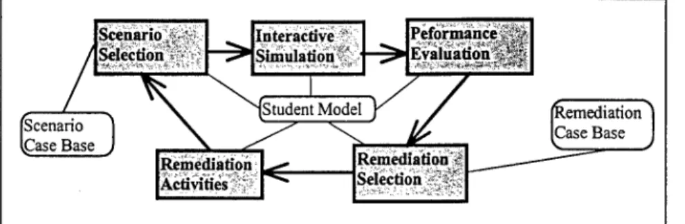
During Phase I, we developed techniques for enhancing the effectiveness of part-task trainers, through the use of an intelligent tutoring system. Intelligent Tutoring Systems track the mental models of students and specialize the training program based on this knowledge. The general flow of information within an intelligent tutoring system is depicted in Figure 1.
Scenario, Selection Interactive Simulation Peforniance Evaluatiönllllsi Scenario .Case Base Remediation Case Base Remediation Activities '
Figure 1. Information Flow in an Intelligent Tutoring System
The data structures shown in the boxes with rounded corners include a scenario case-
base, student model, and remediation case-base. The student model maintains a hierarchy of
principles along with a rating of the students understanding of each principle. The scenario case- base maintains a database of scenarios indexed by the principles they help present. The
remediation case-base maintains a database of remediation activities also indexed by the principles they present. The scenario selection module uses the student model and case-based reasoning to select an appropriate scenario from the scenario case-base. The student is then presented the scenario within an interactive simulation. After the student performs the scenario within the simulation, the student's performance is evaluated and his or her student model is updated based on the principles achieved and missed by the student within the scenario. The
remediation selection module then uses the updated student model to select the appropriate
remediation activities from the remediation case base. The student then performs these activities and his or her student model is once again updated to reflect this activity. If there are still unlearned principles, the student is brought back to the scenario selection module and enters the cycle again.
The ITS cycle described has been successfully applied by SHAI to many different types of training tasks. The challenge of this portion of the Phase I research was to apply it to part-task training and, more importantly, to enable the creation of ITSs for part-task training within a rapid prototyping environment. Typically, when we implement an intelligent tutoring system, a large portion of the time is spent on developing a. principle hierarchy for the domain. A principle hierarchy is a hierarchical breakdown of the various principles being trained and their relationships with one another. This principle hierarchy is extremely important because it determines how the students' mental models are to be built and maintained by the ITS. For this project, however, the emphasis is on building an authoring tool to facilitate the development of
intelligent tutoring systems and part-task trainers. So for our research, we developed a very simple principle hierarchy of the navigational principles of the CDNU. This simple principle hierarchy provided us with a means of testing different ideas for ITS authoring within the context of a rapid part-task trainer prototyping environment. Additionally, a simple scenario case base, sample scenarios and remediation modules were developed. These will be described in more detail in section 3 of this document, which describes the Phase I prototype.
Using this as a starting point, we were able to develop methods for defining the sample data within the part-task trainer prototyping environment. The techniques developed are general enough that they are applicable to virtually any part-task training domain. One or more reusable software components were designed for each of the modules shown in Figure 1. Each of these software components can be specialized for different part-task training domains through the use of custom visual editors. An additional benefit of the approach developed is that it is relatively easy to re-use the same components used for building the ITS for building utility applications geared towards the instructors. These utility applications allow instructors with no programming experience to develop and maintain principle hierarchies, the scenario case base, and the
remediation case base.
A demonstration of these techniques is provided with the presentation of the Phase I prototype, in section 3. The techniques are formally described with the presentation of the Phase II system design, in section 4.
2.4 Proof-of-Concept Prototype
During the Phase I, we implemented a proof of concept prototype which demonstrates the feasibility of a full-scale Trainer-PDE system. This Phase I prototype is presented in detail in section 3. The principle objectives of the Phase I prototype is to validate the part-task trainer prototyping techniques developed and to demonstrate the feasibility of a complete Phase II system. In order to accomplish these goals, we designed the prototype such that it touched on each of the major issues involved with this project. This included the use of reusable software components for rapid part-task trainer prototyping, the use of a distributed object model for distributing the part-task trainer across a LAN or WAN, and the integration of intelligent tutoring systems with part-task training. The construction of the proof-of-concept prototype enabled us to obtain two secondary objectives. The proof-of-concept prototype would serve as a suitable testbed for experimenting with the various concepts involved in this project. This testbed was particularly useful when experimenting with different ways to integrate an ITS with a part-task trainer prototype. Additionally, the proof-of-concept prototype served as a valuable tool for relaying the ideas developed within this project to potential commercial users. An early version of the prototype was demonstrated to personnel in the computer-based training department of HMT-303 at Camp Pendleton. In addition to receiving valuable input, we also received endorsements and potential users for a Phase II effort.
The design and development of the prototype was almost entirely dependent on the completion of other major Phase I research tasks. These tasks included obtaining a
comprehensive understanding of part-task trainers, completing a survey of rapid prototyping technologies, and developing techniques for defining an ITS within a visual development environment. After these tasks were completed, or nearly completed, we spent several months fine tuning the techniques and proving their feasibility through the Phase I prototype. The Phase I prototype developed JavaBean components for use within IBM Visual Age for Java version 2.0 to build a part-task trainer prototype for the navigational procedures of the AH-1W CDNU. JavaRMI was used to demonstrate the benefits of a distributed part-task trainer over a LAN or WAN. Also demonstrated, was how the use of a distributed object model and component oriented programming techniques could abstract away many of the complexities of network
Stottler Henke Associates, Inc. N98-059: Final Report
programming. In designing the Phase I prototype, we took into consideration the task of designing the complete Phase II system which would occur during the last month of Phase I research. We did this such that our Phase I design would be scaleable to a Phase II system design, and so the phase I prototype not only demonstrates the feasibility of the end Phase II system, but it goes further and validates the Phase II system design. The prototype was completed a month before the end of the project completion date.
The navigational procedures of the AH-1W CDNU was selected as a target for the proof- of-concept prototype for several reasons. First off, the instructors and personnel at HMT-303 had identified several flaws with their current CDNU part-task trainers. We felt that successfully addressing these flaws would be a strong way to prove the feasibility of our approach. Other factors included the fact that the domain of the CDNU is highly scaleable. This feature enabled us to scale the domain to a size reasonable for a two-month development effort. Additionally, we found a lot of information about the CDNU within AH-1W NATOPS document. This important consideration enabled us to build a fairly accurate model of some of the CDNU functions. Finally, we felt that a CDNU part-task trainer could touch on each of the technological issues we were interested in demonstrating in this project.
The prototype developed involved a set of JavaBeans components which could be linked together within a COTS environment to build a CDNU part-task trainer. The part-task trainer built included an interactive simulation which could be distributed to several simultaneous users over a network. The part-task trainer also included an intelligent tutoring system which selected scenarios, monitored student performance, and maintained a student model database. Sample multimedia remediation screens were also demonstrated. In many cases, custom user interfaces were developed for the components used to build the part-task trainer prototype. Finally, a sample instructor utility was developed to demonstrate how an instructor might interact with students over a network of part-task trainers.
2.5 Phase II System Design
During Phase I, we developed a system design for the Phase II Trainer-PDE system. This task essentially started when we began the design of the Phase I proof-of-concept prototype. After completing the implementation of the proof-of-concept prototype, we evolved the Phase I design into the Phase II System design presented in section 4. Though the task of designing the Phase II system grew out of the phase I proof-of-concept prototype design, the task was not entirely straight-forward. The proof-of-concept prototype included a proof-of-concept Trainer- PDE system as well as a proof-of-concept CDNU part-task trainer. The design of the Phase II system, however, includes the design of the Trainer-PDE system as well as descriptions as to how to use it to build part task trainers, in a more general sense. To do this, we had to define a general framework capable of supporting the majority of part-task trainer prototypes and then describe how the prototyper should go about using the framework and Trainer-PDE to
implement the part-task trainer. The majority of the less reusable software components will be in the interactive simulation portions of the part-task trainer prototypes. We also describe how reusable software components can be designed, implemented, and used by new interactive simulations. By doing this, the prototype developer will accumulate a library of reusable components which will aid in the design and development of future part-task trainers. More importantly, the use of reusable components will considerably facilitate the maintenance of the part-task trainers developed with Trainer-PDE.
Some principle objectives of creating a full system design of the Phase II system include providing an effective means of documenting our Phase I work and to give us a head start in a Phase II development effort. The Phase II system design is presented in section 4.
3. Phase I Prototype
This section provides an overview of the proof-of-concept prototype developed during the Phase I. The sub-sections refer to screen shots in Appendix A.
3.1 Navigational Procedures of AH-1W CDNU
The target domain of the proof-of-concept prototype is the navigational procedures of the AH-1W CDNU. The CDNU is a device on the AH-1 W helicopter which is used for a variety of navigation and communication tasks. The CDNU on the AH-1W is comprised of an alpha- numeric keypad along with function keys and a small text display area. The CDNU interfaces a number of navigational and communications equipment including sensors, radios, radar, TACAN, and more. The pilot navigates through the CDNU data pages and uses the keypad to enter information. The CDNU then uses this information to configure the appropriate sensors or radios. The CDNU is also available to display various information about the equipment it interfaces. For example, a typical task the CDNU is used for, is entering a longitude/latitude location as a destination along with a desired time of arrival. The CDNU will then compute the direction and speed the pilot must fly his or her helicopter in order to arrive at that location at that time.
To limit the scope of our work such that it could be completed in a two-month
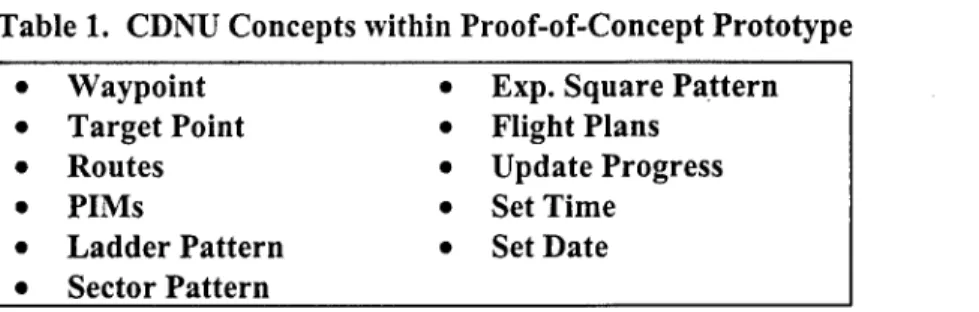
development effort, we chose to focus on a limited set of the navigation procedures. Table 1 lists the navigation procedures we chose to cover in the Phase I proof-of-concept prototype.
Table 1. CDNU Concepts within Proof-of-Concept Prototype
• Waypoint • Exp. Square Pattern
• Target Point • Flight Plans
• Routes • Update Progress
• PIMs • Set Time
• Ladder Pattern • Set Date
• Sector Pattern
One of the reasons why the tasks in Table 1 were selected for this prototype was because they were believed to be fairly easy to model within a low fidelity simulation. Also, though these tasks are fairly basic and straight-forward concepts, they represent some of the more common navigational tasks the CDNU is used for. Therefore, it is very important that a pilot can routinely perform these sorts of tasks. A principle goal of the part-task trainer is to internalize these procedures into the AH-1W pilot to the extent that he or she can perform them with very little conscious effort. This will free up valuable cognitive resources for more of the pressing tasks of piloting the helicopter and/or assessing the current tactical situation.
To learn all the necessary information regarding the AH-1W CDNU, we primarily referenced the AH-1 W NATOPS manual. When questions arose, we would direct them to contacts at HMT-303. This domain for part-task training served us well for the proof-of-concept prototype. The domain would also be a strong candidate for an operational prototype Phase II system. A phase II system would train the full suite of CDNU tasks including all navigation and communication procedures.
3.2 Proof-of-Concept Rapid Prototyping
In order for the Phase I to be successful, it was important to demonstrate how rapid prototyping techniques could be used for part-task trainer development. In order to demonstrate
Stottler Henke Associates, Inc. N98-059: Final Report
this, we developed a proof-of-concept prototyping environment for part-task trainer
development. This proof-of-concept prototyping environment consisted of all the necessary components to build the scaled CDNU part-task trainer. Essentially, the rapid prototyping environment was a very scaled down version of what the end Phase II system will look like. The prototyping environment developed only needed to focus on the components required to build a CDNU part-task trainer, as opposed to a Phase II system which must be general enough to build essentially any part-task trainer or, at the very least, provide a significant head start on the prototyping process.
The Phase I rapid prototyping environment consisted of a set of custom JavaBean components and a COTS tool which supported the JavaBean object model. The Java
Development Kit version 1.1.6 was used to compile the custom JavaBeans. The components were organized into palettes and linked to build part-task trainers within IBM VisualAge for Java. Theoretically, any of the many COTS tools which supported the JavaBean component model could have been used for this purpose. Some of these other COTS tools include Inprise Jbuilder 2.0, Sun Java Workshop 2.0, Lotus BeanMachine, Symantic Corp. Visual Cafe for Java, NetBeans 2.0, and many more.
Within the protoyping environment each component is associated with a set of properties along with property values, custom property editors, events accepted, and events fired. The prototype developer selects the desired component from a palette and places it on the canvas. The prototype developer then specializes the component by assigning values to the components properties. The task of assigning values to the component instances properties is facilitated by custom, user friendly, property editors. Communication between the various components is specified through the event model. Each component specifies the types of events it fires and the types of events it knows how to handle. The user then uses the COTS tool to graphically draw connections between components and specify which events traverse these connections.
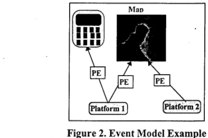
For example, we developed a platform component to represent the state of a platform,
such as an AH-1W helicopter. We then created an instance of this platform component to represent the helicopter which the CDNU is located in. We used a property editor to set location, heading and speed information, amongst other properties for the platform component. The platform component type fires a platform event every time one of these properties change. A CDNU component and map component were designed to know how to handle these platform events. The CDNU component uses the platform event information to update its internal data and to display information about the platform. The map component uses the platform event information to redraw the map and illustrate the new location of the platform. To enable these components to interact as desired, we next drew connections between the instance of the platform component and the instances of the CDNU and the map components. This connection specifies that platform events should be passed from the platform component instance to the CDNU and map component instances. Suppose now that we wish to instantiate another platform component to represent the aircraft carrier platform the AH-1W should land on. We draw a connection from this new platform instance to the map display component. The map component will now display the location of the aircraft carrier as well as the helicopter. Note, however, that we do not draw a connection from this new platform instance to the CDNU component, because the CDNU has nothing to do with this platform. This example is illustrated in Figure 2.
MaD
t^^^m)
■ III' ■ III■ ■■■
\
PEV
PE PE \ [Platforml] >Iatform2]Figure 2. Event Model Example
The components for building the AH-1W part-task trainer were divided into palettes, based on their functionality. These palettes included multimedia (TPDE-MM), simulation (TPDE-SIM), familiarization (TPDE-FAM), intelligent tutoring system (TPDE-ITS), and
networking (TPDE-NET). Additional components were built which were specific to the AH-1W
CDNU. The prototype developer selected components from these palettes and placed them on the canvas, thus creating an instance of the selected component. The prototype developer then customized the properties using custom editors, and connected the component instances by connecting them to the event handlers of other components. This technique was used to build a scaled down CDNU part-task trainer. This included a distributed simulation environment, familiarization routines, student model server, simulation server, and an instructor utility. Each of these processes will be described in detail later in this document.
The rapid prototyping techniques demonstrated with the proof-of-concept prototype clearly depicted their effectiveness at building part-task trainer prototypes. The methods used partially automate many of the repetitive steps involved with building new part-task trainers. The proof-of-concept prototype also demonstrates the high-level of reusability of the software components developed. Many of the same software components are reused in different aspects of this project. Finally, the maintainability of part-task trainers developed using these techniques is illustrated. A change to an actual CDNU device would in most cases only require the
prototype developer to modify the model of the CDNU in one location. All of the ITS and computer networking code does not need to be touched. Also, if this component is used in several applications, then all changes to the CDNU can appear instantly in each of these
applications. That is, we don't need to explicitly modify each application which uses the CDNU. Since all of these applications refer to the same component, all we have to do is modify this single component.
3.3 Distributed Architecture
One of the desired objectives of the Phase I prototype is to demonstrate the benefits of a distributed architecture for the part-task trainers. To accomplish this, we employed a simple distributed object model in the architecture of the Phase I prototype. The principle advantages of a distributed architecture that we want to illustrate include:
• Distributed Simulation Environment
• Team or Group Training
• Centralized Student Model Database • Instructor Utilities
The distributed architecture of the Phase I prototype consists of four different types of processes which can execute on any machine within a network (note, this may be the same
Stottler Henke Associates, Inc. N98-059: Final Report
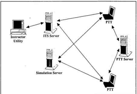
machine or separate machines). A student model server provided a centralized database for student models, thus allowing mobile users to take full advantage of the student modeling capability and ITS from any location. A simulation server coordinated a distributed simulation environment for the students. The part-task trainer clients have the ability to connect to the simulation server and thus enter the student into the distributed simulation. An instructor utility demonstrated a second advantage of centralized servers. It enabled instructors to closely monitor the student's progress, possibly from a remote location. It also demonstrated how an instructor might intervene with a training sessions, if necessary. Figure 3 below illustrates the operating context of this architecture.
J351
Instructor ITSServcr
Utility
Simulation Server
PTT
Figure 3. The distributed operating context of Phase I prototype
The above architecture was implemented using the Java Remote Method Invocation protocol. Distributed object protocols such as JavaRMI enable the programmer to refer to remote objects in nearly the same manner as they refer to local objects. This effectively
abstracts many of the details of computer networking from the programmer. It also enabled us to support the use of distributed application architectures within a rapid prototyping environment. For example, in order to enable an ITS component instance to use a remote student model server, the prototype developer simply instantiates an instance of the student model server client
component and connects it to the ITS component instance. The prototype developer doesn't need to know about the details of the computer network to successfully perform these tasks.
Despite the usefulness of the distributed architecture, it is import to recognize that a computer network may not always be available. Many of the overseas and ship-based training facilities have very few, if any, computer networks. To accommodate this, we were sure to implement the Phase I such that it could operate just as effectively in a standalone environment.
3.4 Intelligent Tutoring System
In addition to illustrating how part-task trainer prototypes could be built using the rapid prototyping techniques developed, we also wanted to demonstrate the benefits of integrating an intelligent tutoring system with a part-task trainer. This includes demonstrating how an ITS can be built using the rapid prototyping techniques developed and how the resultant part-task trainer will be a more effective training tool. To demonstrate these benefits, we once again turned to the domain of the AH-1W CDNU. We designed a simple intelligent tutoring system for training the CDNU navigation principles listed in Table 1. This ITS employed the general architecture illustrated in Figure 1.
The task of building the proof-of-concept intelligent tutoring system for the navigational procedures of the CDNU involved several sub-tasks. We needed to develop methods for
building intelligent tutoring systems using the rapid prototyping paradigm. More specifically, we needed to design and implement reusable software components for building an ITS. We then needed to use these component oriented programming techniques to build a proof-of-concept part-task trainer for the CDNU. This involved defining a principle hierarchy, creating the interactive simulation, creating a scenario case-base, creating a remediation case-base, and creating remediation activities. Notice how each of these tasks corresponds to a module, or box, from Figure 1.
One of the most important parts of an ITS is the principle hierarchy. The concepts selected for this part-task trainer (see Table 1) were relatively straight-forward, so the principle hierarchy is not too complicated. Also, the focus of this portion of the research was on
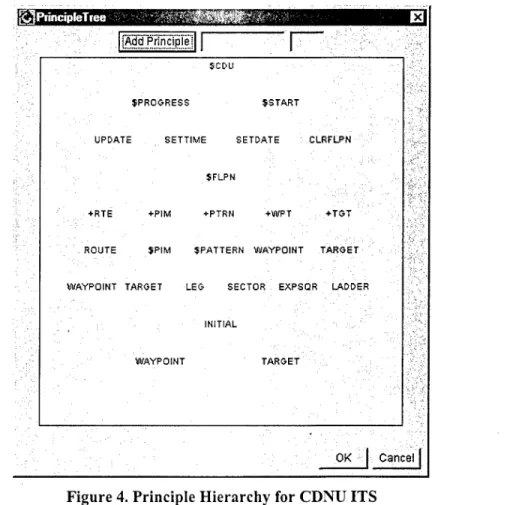
integrating intelligent tutoring systems with part-task training. Because of this, more time was spent on fine tuning techniques and less on the content of the ITS. Nonetheless, a fairly comprehensive principle hierarchy was developed for this project. This principle hierarchy is shown within a custom property editor in Figure 4.
iOPiincipleliee jKltf-4jf - Ql jÄddJPriricipiei
SCDU
JPROGRESS $START
UPDATE SETTIME SETDATE CLRFLPN ■
$FLPN
+RTE +PIM +PTRN +WPT ...+TGT
ROUTE JPIM JPATTERN WAYPOINT TARGET ::
WAYPOINT TARGET LEG SECTOR EXPSQR LADDER
INITIAL
WAYPOINT TARGET ;
OK | Cancel |
Figure 4. Principle Hierarchy for CDNU ITS
^principle hierarchy is used by the ITS to determine the relationships between the
various principles involved in the training domain. In Figure 4, for example, the concept of
Route is dependent upon the understanding of the Waypoint and Target principles. The ITS uses
these relationships to determine which scenario or remediation activity to present to the student next. That is, if the student understands the waypoint and target principles, then the ITS will present the student with a scenario involving routes. The student will not be presented with a
Stottler Henke Associates, Inc. N98-059: Final Report
scenario involving routes until he or she demonstrates an understanding of the target and waypoint principles. A student model database keeps track of the principles the student understands, fails to understand, or has not yet seen. The student model also keeps track of the scenarios and remediation activities the student has experienced. The instructor utility presented in section 3.5 provides a mechanism for browsing the student model information stored within the student model database.
Principle hierarchies can be constructed by instantiating a principle hierarchy component and then utilizing the custom property editor (shown in Figure A) to build the graph of principles. Special characters within the various principles have special meanings to the ITS algorithm. For example, the '$' in the "SFLPN" principle signifies that the SFLPN principle is considered understood when all of its sub principles are understood. This is as opposed to the "ROUTE" principle, which is a principle in itself which is also dependent upon the understanding of its sub- principles. Note, these types of semantics could have been avoided by creating a more intricate principle data structure. However, these semantics were found to be a useful shortcut for the short amount of development time for implementing the Phase I prototype. The Phase II system will be more thorough in its definition of a principle.
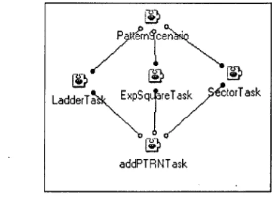
The scenarios were selected by comparing the principles the student understands with the principles exemplified by scenarios within a scenario database. The construction of the scenario database was done graphically through the use of scenario and task components. The prototype developer builds a scenario by creating a scenario component and connecting a network of tasks and sub-tasks to that scenario. Each task includes a description, which describes the actions which the user must perform; a set of parameters, which are used to determine if the student successfully performed the task; and a set of principles, which signify the concepts the task exemplifies. The network of tasks determine the dependency between the various portions of the scenario. A simple example of a scenario is shown in Figure 5.
addPTRNTask
Figure 5. Simple Scenario from Phase I Prototype
In this scenario, the user must complete the LadderTask, ExpSquareTask, and
SectorTask before he or she will be asked to perform the AddPTRNTask. This is a graphical way
of signifying that the student must understand all of the basic pattern principles before learning how to add a pattern to a flight plan. These types of statements can be used to build extremely intricate scenarios and an extensive scenario database. Examples of this are presented in the Appendix.
Other major portions of the ITS from the Phase I, include a student model database and a student model server. The student model database provided a centralized location for the storage of student models. These student models were distributed to the intelligent tutoring systems over a computer network via the student model server. The student model server enabled a student to use any part-task trainer connected to the network. Whichever part-task trainer the student logs
on to would access the centralized student model server to acquire up-to-date information about the student.
The final major ITS component from the proof-of-concept prototype are the familiarization pages. Familiarization pages are a multimedia presentation of the course
information. These familiarization pages are used as the principle remediation activity suggested by the ITS. They may be direct multimedia presentations of the principles or they may be plain text instructions such as review pages 179-200 in the NATOPS manual or go see instructor Y. Screen shots and examples of these ITS components are presented in the Appendix.
The development of the ITS portion of proof-of-concept prototype was a success. The experience not only resulted in an effective demonstration tool, but also served as a testbed for experimenting with the different ITS concepts involved. This experimentation paid off in the Phase II design of these ITS components.
3.5 Simulation Environment
A significant amount of development time was spent designing and developing the CDNU simulation environment. This portion of the Phase I prototype is extremely important for several reasons. First off, the simulation environment is perhaps the most visible portion of the prototype. Also, the simulation environment is where the majority of the learning will take place. We had several objectives for the simulation environment of the proof-of-concept
prototype. One objective was to model the CDNU navigation procedures as precisely as possible within the amount of time available for development. Also, we wanted to provide some forms of engaging multimedia feedback to the student. This is one of the identified limitations of current part-task trainers and we wanted to demonstrate that it could be overcome efficiently. Also, we wanted the simulation environment to be distributed. A distributed simulation will aid in the students experience by making the simulation more interesting. Also, a distributed simulation could potentially be used for team training. Finally, the simulation environment needed to have the ability to run the scenarios defined in the ITS components and provide hooks, such that the ITS components could monitor the student's performance within the simulation environment.
The simulation environment which was developed, involved a handful of software components. One component included a software model of the CDNU along with a graphical mock up of the device. This component enabled the user to perform many of the CDNU navigational procedures within the simulation environment. In addition to being used within the simulation environment, this component was used within several familiarization pages. Another component developed is a multimedia map component. The multimedia map component played a significant role in the simulation, by engaging the students interest and providing multimedia feedback to his or her actions. Additionally, the map display component depicts the platforms of every student within the distributed simulation. This further enhances the user experience and alludes to how the part-task trainer may be used for team training. Additionally, other simple instrument components were created to provide access to important information and feedback to the student. These instruments included speedometer and compass. Controls for entering a distributed simulation, modifying the simulation's settings, and logging on to the ITS were also created. Additionally, message window components were created for displaying ITS-specific messages and for displaying general simulation messages to the student. Finally, several non- visual components were developed to handle the internal logic of the part-task trainer. These non-visual components included platforms, a timer for synchronization, modules for doing navigational computation, and several others. These components were linked in with the ITS and distributed simulation components. Screen shots of the development environment and the end part-task trainer can be found in the Appendix.
Stottler Henke Associates, Inc. N98-059: Final Report
The simulation environment developed attained its goal of providing a multimedia-rich model of the CDNU and various feedback components. Because the development of the simulation environment followed the component oriented programming event model, it was extremely straight-forward to integrate with the ITS. To integrate the ITS, all we had to do was enable the ITS to catch the simulation events and determine if they match any of the tasks currently assigned to the student. The ITS used a message window to pass information to the student and to request the student to perform specific tasks.
3.6 Instructor Utility
A simple instructor utility was developed to demonstrate one of the advantages of the distributed architecture. This utility enables instructors to monitor a student's progress from a remote location. The instructor utility simply connects to the central student model database and displays up-to-date information about the student's mental model. This information includes a color coded graph of the principles the student has achieved, missed, or not yet seen, as well as a list of scenarios the student has seen. Other possible uses of an instructor utility would be to allow the instructor to modify the principle hierarchy or the student model in some way. Also, the instructor may suggest which scenario the student should perform next or even interact with the student in some way through the distributed simulation environment.
The instructor utility developed for the proof-of-concept prototype used many of the same software components as the CDNU part-task trainer prototype. This property enabled us to implement the instructor utility in a very short amount of time. Screen shots of the proof-of- concept instructor utility can be found in the Appendix.
4. Phase II System Design
This section provides an overview of the Phase II Trainer-PDE system design developed during the Phase I research.
4.1 Operational Trainer-PDE Prototype
The Trainer-PDE system is a rapid prototyping environment for building part-task trainers. The resultant part-task trainer prototypes implemented with this system will incorporate intelligent tutoring systems to cater training programs to specific individuals. The environment and resultant part-task trainer prototypes will take advantage of Internet/intranet technologies to enhance portability and enable the part-task trainer prototypes to take advantage of computer networks. Additionally, the system will be capable of running as a standalone system when no network is available. The prototyping environment will take advantage of open standards, component models, and commercial-off-the-shelf software. This awareness of software engineering trends will enable the Trainer-PDE system to maximize reuse and provide an environment to efficiently prototype part-task trainers.
Many inter-related concepts are involved in the Trainer-PDE system. A thorough understanding of each of these concepts is required for designing and implementing the Phase II operational Trainer-PDE prototype. These concepts include:
• Part-Task Trainers (PTT) • ITS Authoring Tools
• Distributed Part-Task Trainers • Component Models
• Rapid Prototyping Environment • Distributed Object Models
4.2 Trainer-PDE System Overview
This sub-section describes the high-level system overview for the Trainer-PDE system. This includes the major components of the system and how these components interact to provide an effective tool for prototyping part-task trainers. The next section will describe the system architecture at a more detailed level.
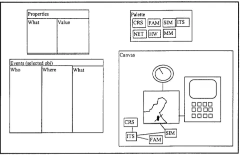
The system will be comprised of a set of software components designed for use within a COTS tool to build part-task trainer prototypes. These components will be divided into palettes based on their functionality. These palettes of components are imported into the COTS tool and used by the developer to build part-task trainers. Figure 6 illustrates how these components might appear within a COTS visual development environment. Notice how this roughly resembles the screen shots from the Phase I prototype, in the Appendix. This is because the proof-of-concept prototype followed a very similar design as the one presented here. Essentially, the proof-of-concept prototype is truly a scaled-down version of Trainer-PDE. This is as
opposed to many proof-of-concept prototypes which simply provide a visual mock-up of what an end system will look like, without modeling any internal behavior.
Properties What Value
Palette
CRS |FAM| SIM ITS [NET j |HW 1 |MM
Canvas Events (selected obi)
Who Where What
CRS
V J
GGGG GGGG GGGG
Figure 6. Rapid Prototyping Environment within a COTS tool
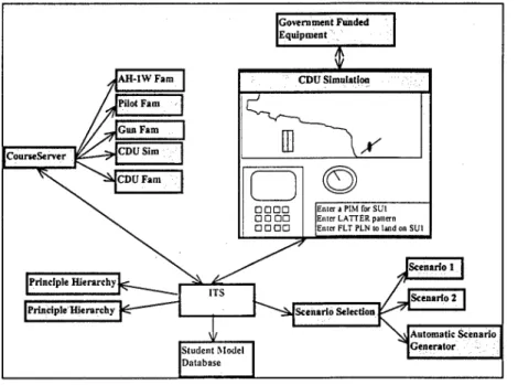
The palette provides an interface for selecting a component to use in the part-task trainer prototype. These components are placed on a canvas and visually manipulated using custom properly editors and event editors. Figure 7 illustrates how these component instances might appear on the canvas. This particular figure represents how the components would be used to build a part-task trainer for the CDNU. However, other part-task trainers will have a very similar architecture. The major differences will reside in the simulation components of the part- task trainers. Properly editors and events provide mechanisms for describing how the
component instances behave and how they will interact with one another. Using the COTS tool to graphically connect component instances on the canvas will describe the directions that the events flow. Selecting a connection will bring the user to an event editor where the user can formally describe the information passed between the components. Selecting an instance of a component will bring the user to a properly editor where the user can specify values for the components member variables. The functionality described is provided by COTS tools which support the component model used to build the Trainer-PDE components. For example, if JavaBeans is used to implement Trainer-PDE, then IBM Visual Age for Java or Sun Java Workshop may be used to connect and edit the components. The Trainer-PDE system will be
Stottler Henke Associates, Inc. N98-059: Final Report
composed of implementations of components, custom events, custom event editors, and custom property editors, all geared towards rapid prototyping of part-task trainers. Additionally, templates and roadmaps will be provided to ease new developers into the rapid prototyping paradigm.
Government Funded Equipment'
CourseServer
Enter a PIM for SU1 Enter LATTER pattern Enter FLT PLN to land on SU1
[Principle Hierarchy!
iPrincipleUierarchy ] Scenario Selection
IScenario 1 IScenario 2 Student Model Database Automatic Scenario Generator
Figure 7. Rapid Prototyping Environment
As a final note on Figure 7, notice how the physical layout of the components
represented by shaded boxes, and the event connections represented by arrows, closely resembles an architectural design for the part-task trainer as it might appear in an object modeling tool such as Rationale Rose. However, unlike an object modeling tool, these boxes are actual component instances and with a click of a button, the application can be executed. This is rapid prototyping - the bridging of the design, implementation, and testing phases of prototype development.
4.2.1 Components
The reusable software component will form the foundation of the Trainer-PDE system. A software component is defined by a software object which conforms to some standard
interface. This standard interface allows the public member variables and public methods of the component to be realized at run-time, thus enabling their use within a visual development environment. There are many standard component models and many COTS visual development environments which support these component models. The majority of the tasks for
implementing the operational Trainer-PDE prototype will include implementing the sets of software components for building distributed part-task trainer prototypes, defining the custom events which enable these components to interact, and developing the custom editors for defining and manipulating component properties and events.
4.2.2 Palettes
The Trainer-PDE System will be divided into palettes based on the functionality of the components. These palettes will include the following: course structure (TPDE-CRS), intelligent tutoring systems (TPDE-ITS), multimedia (TPDE-MM), familiarization (TPDE-FAM),
simulation (TPDE-SIM), network (TPDE-NET), and hardware (TPDE-HW). The components of these palettes will be edited and linked together within a COTS visual prototyping environment.
Each component is defined by a set of properties, set of events it can handle, and a set of events that it fires. Custom property editors and custom event editors will be developed to edit the components properties and events.
4.2.3 Event Model
The components will communicate with one another using custom events. Each component specifies the types of events it can send and the types of events it fires. Information will be passed between components through these custom Trainer-PDE events. Components will respond to these events based on the information they pass. Each component may define its own type of events and each component can define its own set of event handlers for existing events.
Simulation components, for example, will define several events for passing information amongst objects within the simulation. Intelligent tutoring system events will be used for passing information amongst the ITS objects. A simulation event titled task event will be fired every time the student performs some task within the simulation. The task event will pass along information about the task in its parameters. The task type waypoint_entered and the parameters
lattitudejc and longitude_y may be passed as the task parameters. The ITS component instance
will be specified to catch these events. When these events are caught by the ITS component, the ITS component will check to see if they match a current task assigned to the student and whether the student performed the task correctly. This information will then be used to update the student model.
There are many other examples of how events will be used. Some of these include a
timer event, which will fired by a clock component instance every so many milliseconds, a platform event, which will be fired by the platform component every time the platforms state
changes, an update distributed simulation event, which will be fired by the distributed simulation
server component every time the distributed simulation needs to be updated, and many more.
The use of an event model