User Capacity Analysis and Pilot Design for
Multi-Cell Multiuser Massive MIMO Networks
Noman Akbar,
Student Member, IEEE,
Nan Yang,
Member, IEEE,
Parastoo Sadeghi,
Senior Member, IEEE,
and Rodney A. Kennedy,
Fellow, IEEE
Abstract
We propose a novel pilot sequence design to mitigate pilot contamination in multi-cell multiuser massive multiple-input multiple-output networks. Our proposed design generates pilot sequences for all users in the multi-cell network and devises power allocation at base stations (BSs) for downlink transmission. The pilot sequences together with the power allocation ensure that the user capacity of the network is achieved and the predefined signal-to-interference-plus-noise ratio (SINR) requirements of all users are met. To realize our design, we first derive new closed-form expressions for the user capacity and the capacity region of the network. Built upon these expressions, we then develop a new algorithm to obtain the required pilot sequences and power allocation. We further determine the minimum number of antennas required at BSs to achieve certain SINR requirements of all users. Numerical results are presented to corroborate our analysis and to explicitly examine the impact of key parameters, such as the pilot sequence length and the total number of users, on the network performance. A pivotal conclusion is reached that our design achieves a larger capacity region, supports a more diverse range of SINR requirements, and needs a lower number of antennas at BSs to fulfill the predefined SINR requirements than the existing designs.
Index Terms
Pilot contamination, generalized Welch-bound-equality, multi-cell multiuser massive MIMO, user capacity.
N. Akbar, N. Yang, P. Sadeghi, and R. A. Kennedy are with the Research School of Engineering, Australian National University, Acton, ACT 2601, Australia (e-mail:{noman.akbar, nan.yang, parastoo.sadeghi, rodney.kennedy}@anu.edu.au).
I. INTRODUCTION
Massive multiple-input multiple-output (MIMO) has been identified as one of the indispensable technologies to support ultra-high data rate for a huge number of mobile users in the fifth generation wireless systems [1–3]. The key distinguishing feature of massive MIMO from conventional MIMO lies in the very large number of antennas deployed at base stations (BSs), which offers favorable propagation conditions as well as boosts energy efficiency and spectral efficiency [4, 5]. It is widely recognized that the use of hundreds of antennas incurs a significant channel estimation burden in massive MIMO networks. To relieve this burden, the time-division duplex (TDD) mode is preferred to be used together with massive MIMO over the frequency division duplex mode [6, 7]. In the TDD mode, the uplink and the downlink share the same frequency band such that the channel estimated through the uplink can be utilized in the downlink transmission [8].
A. Background and Motivation
Pilot contamination has been identified as one of the key challenges to unlock the full potential of massive MIMO [9–11]. Principally, pilot contamination occurs when non-orthogonal pilot sequences are assigned to users. In typical massive MIMO networks, a huge number of users are served but only a limited number of orthogonal pilot sequences are available. As such, pilot contamination is a commonly encountered problem and a major performance limiting factor in massive MIMO networks.
Some significant efforts have been devoted to address the pilot contamination problem in massive MIMO networks. These efforts are referred to as conventional methods and classified into four broad categories [7]: 1) the protocol-based method, which restricts the simultaneous transmission from the users having the same pilot sequence or wisely assigns pilot sequences among users to alleviate pilot comtamination (e.g., [12–14]), 2) the precoding-based method, which uses precoders to reduce the interference caused by pilot contamination (e.g., [15]), 3) the angle-of-arrival (AoA)-based method, which mitigates the interference from the users having the same pilot sequence and mutually non-overlapping AoA (e.g., [16]), and 4) the blind method, which partitions the signal space into desired signal subspace and interference signal subspace and then develops algorithms to reduce the interference from the latter (e.g., [17]). It is worth mentioning that most conventional methods, e.g., [12, 15, 16], assumed orthogonal pilot sequences to perform pilot contamination analysis.
Recently, increasing attention has been paid to an alternative method, i.e., pilot sequence design, which aims at directly mitigating the detrimental impact of pilot contamination on the performance of massive MIMO networks. For example, when the number of users in the massive MIMO network exceeds the length of pilot sequence, [18] designed pilot sequences by solving a line packing problem in Grassmannian manifold. Different from [18], [19] designed pilot sequences by solving an optimization problem aiming at maximizing the received signal-to-noise ratio. We note that neither [18] nor [19] considered the signal-to-interference-plus-signal-to-noise ratio (SINR) requirements of individual users in designing pilot sequences. Hence, the results in [18, 19] cannot evaluate a pivotal performance indicator of the massive MIMO network, namely, the user capacity. Against this background, [20] evaluated the user capacity of a single-cell multiuser massive MIMO network. Taking the effective bandwidth into account, [21] explored the feasibility conditions of the same network. We note that the limitation of [20, 21] lies in the assumption of perfect channel knowledge at the BS. This assumption does not generally hold in practice. To overcome this limitation, [22] proposed a capacity-achieving pilot sequence design together with power allocation for downlink transmission of a single-cell multiuser massive MIMO network. While [22] laid a solid foundation to design pilot sequences in the single-cell network, the design of capacity-achieving pilot sequences in the multi-cell multiuser massive MIMO network has not been explored in the literature. We clarify that this design is not trivial since multiple cells impose additional constraints that need to be satisfied. First, the design needs to ensure that the user capacity in an individual cell and the whole network is achieved. Second, the design needs to minimize the required cooperation among BSs for the ease of implementation.
B. Contributions and Novelty
In this paper, we mitigate pilot contamination in a multi-cell multiuser massive MIMO network by designing capacity-achieving pilot sequences with low correlation coefficients. Crucially, our proposed design generates pilot sequences for each cell independently. The generated pilot sequences and the corresponding power allocation scheme satisfy the SINR requirements of all users in the network, regardless of the severity of pilot contamination. Our design is based on
the rules of the generalized Welch-bound-equality (GWBE) sequence design1. The contributions and novelty of this work are summarized as follows:
• We derive a new closed-form expression for the user capacity of the multi-cell multiuser
massive MIMO network. This expression explicitly reveals that the user capacity is limited by the effective bandwidth2, the length of pilot sequence, the number of cells, and the number of users in each cell. Based on this expression, we derive a simple yet valuable result to determine the capacity region of the network, under which the SINR requirements of all users are always satisfied.
• We propose a new algorithm to generate capacity-achieving pilot sequences based on the
derived capacity region. The pilot sequences are independently generated for each cell. Thus, the proposed algorithm requires no cooperation among BSs. We also devise the power allocation scheme to control the downlink transmit power at each BS. This scheme only requires the BSs to exchange the correlation coefficient between pilot sequences with each other.
• We determine the minimum number of antennas required at BSs to achieve certain SINR
requirements of all the users. This result is of practical significance since it avoids the uneconomic hardware costs caused by using unnecessary antennas to deliver the required quality of service.
• We analytically compare the performance of our design with that of two existing pilot
sequence designs, namely, the Welch-bound-equality (WBE) design and the finite orthogonal set (FOS) design. Based on the analysis, we demonstrate that our design achieves a larger capacity region than the existing designs.
Beyond the aforementioned contributions, we undertake a series of numerical evaluations to offer practically important insights into our design. First, the upper surface boundary of the
1
The GWBE sequence has been shown to achieve the user capacity in overloaded code-division-multiple-access (CDMA) systems [23, 24]. We note that most studies on the signature sequence design in CDMA systems considered a single cell, e.g., [25, 26]. Even when the multi-cell CDMA system was considered, e.g., [27], the focus was to investigate hard hand-offs, rather than signature sequence design. This indicates the novelty of designing GWBE pilot sequences in multi-cell multiuser massive MIMO networks.
2
The effective bandwidth is a concept adopted in CDMA systems (e.g., [21, 23]). It represents a fraction of available degrees of freedom (i.e., the pilot sequence length) required by a user to achieve its target SINR. A user having a high SINR requirement requires a large fraction of available degrees of freedom and accordingly a large effective bandwidth. We clarify that the effective bandwidth is different from the channel bandwidth.
l BS i-th cell l-th cell ij U lk U M antennas M antennas i BS √ √
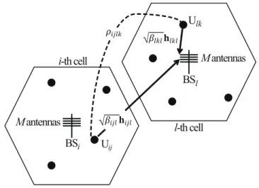
Fig. 1. Illustration of a TDD multi-cell multiuser massive MIMO network withL= 2,K= 4, andKtot= 8. The uplink channel
estimate is corrupted by pilot contamination when non-orthogonal pilot sequences are used in the network, i.e.,ρijlk6= 0.
capacity region of our design is higher than that of the existing designs, indicating that our design is capable of supporting a more diverse range of SINR requirements of users. Second, the maximum individual SINR requirement in each cell decreases when the total number of users increases. Third, our GWBE design fulfills the SINR requirements of all the users throughout the network, while the existing designs are unable to fulfill the same SINR requirements. Fourth, our GWBE design requires less number of antennas to achieve the predefined SINR requirements than the existing designs.
Notations: Vectors and matrices are denoted by lower-case and upper-case boldface symbols, respectively. (·)T denotes the transpose, (·)H denotes the Hermitian transpose, ⊗ denotes the
Kronecker product, E[·] denotes the mathematical expectation, k · k denotes the l2 norm, tr(·)
denotes the trace operation, and var(·) denotes the variance operation.
II. MULTI-CELL MULTIUSER MASSIVEMIMO NETWORKS WITHPILOTCONTAMINATION
We consider a TDD multi-cell multiuser massive MIMO network, an example of which is depicted in Fig. 1. The network consists ofLcells. In each cell, a BS equipped withM antennas communicates with K users, equipped with a single antenna each. We denote Ktot as the total number of users in the network, where Ktot = KL. We also denote BSl as the BS in the l
-th cell, where l ∈ {1, . . . , L}. We further denote Uij as the j-th user in the i-th cell, where
We consider a block fading channel model, where the channel remains constant during the coherence time interval, T, and changes independently every interval. We denote hijlm as the
small-scale fading coefficient from Uij to the m-th antenna at BSl, where m∈ {1, . . . , M}. We
assume that the small-scale fading coefficients in the network are subject to independent and identically distributed (i.i.d) Rayleigh fading. This assumption is reasonable in practice since the i.i.d Rayleigh fading model has recently been shown to agree well with the experimental data in massive MIMO [28]. Based on this assumption, we find that hijlm follows a complex
Gaussian distribution with zero mean and unit variance, i.e., hijlm ∼ CN(0,1). We next denote
βijl as the large-scale propagation factor from Uij to BSl, which captures the effects of path
loss and shadowing [15]. Based on βijl and hijlm, the overall propagation factor from Uij to m-th antenna at BSl is given by
p
βijlhijlm. We highlight that the multi-cell multiuser massive
MIMO network considered in this paper is a generalized model that describes a wide range of cell layouts.
Throughout this paper, we assume that the network operates in the TDD mode. In this mode, the uplink and the downlink channels are reciprocal such that the frequency band for uplink training is the same as that for downlink transmission. This allows the BSs to utilize the propagation factor estimated during uplink training in downlink transmission. We note that the use of the TDD mode is a fairly common assumption for massive multiuser MIMO networks [29, 30]. Furthermore, we assume that the uplink training and downlink transmission time is less than or equal to the channel coherence interval.
A. Uplink Training
We first focus on the uplink training phase, during which the users in each cell send pilot sequences to enable channel estimation at the same-cell BS. At the beginning of each coherence interval, theK users in thel-th cell send their pilot sequences of lengthτ to BSl in pre-assigned
time slots. Assuming perfect synchronization, the pilot sequence vector received at BSl during
the uplink training phase, denoted by a τ M ×1 vector, yl, is given by
yl = L X i=1 K X j=1 p pijβijlSijhijl+zl, (1)
where pij is the pilot power at Uij, Sij = sij ⊗IM is a τ M ×M matrix, sij is a τ ×1 pilot
from Uij to BSl, and zl∼ CN(0, σ2zl)is the τ M×1additive white Gaussian noise (AWGN) at
BSl.
We assume that the pilot sequences are real and have unit energy. We note that the pilot sequences matrix Sij has a useful property, i.e., STijSij = IM. Additionally, we denote ρijlk = sTlksij as the correlation coefficient between different pilot sequences, where k ∈ {1, . . . , K}. The value of ρijlk varies from −1 to +1. Here, +1 indicates a perfect positive correlation
coefficient, −1 indicates a perfect negative correlation coefficient, and 0 indicates orthogonal pilot sequences with no correlation. Of course, the ideal value for ρijlk is zero. However, this
ideal value is not achievable in practical multiuser massive MIMO networks, which gives rise to pilot contamination.
The uplink channel vector hlkl between Ulk and BSl is estimated at BSl based on yl. We
assume that the low-complexity least square (LS) channel estimation is performed to obtain an estimate hˆlkl for the uplink channel vector hlkl. It has been demonstrated that mean square
error of an LS channel estimator remains nearly constant as M increases [10], which makes it attractive for massive MIMO networks. As per the rules of the LS channel estimation, hˆlkl is
given by ˆ hlkl =STlkyl =STlk L X i=1 K X j=1 p pijβijlSijhijl+zl ! . (2)
Moreover, we consider that the uplink power control is enabled such that pljβljl = 1 [22].
Accordingly, we re-express (2) as ˆ hlkl =hlkl+ X i,j6=l,k ρijlk p pijβijlhijl+STlkzl, (3) where P i,j6=l,k = PL i=1 PK j=1 and (i, j)6= (l, k).
The effect of pilot contamination on the channel estimate can be easily seen from (3). When
ρijlk 6= 0, i.e., the correlation coefficient between the pilot sequences assigned to different users
is non-zero, the channel estimate ˆhlkl is contaminated by undesired channels hijl.The non-zero
correlation coefficient is caused by the limited number of orthogonal pilot sequences available in the network. Particularly, the short length of coherence interval does not allow for a long length of pilot sequence. If the total number of users in the network exceeds the pilot sequence length, i.e., Ktot> τ, the same pilot sequence needs to be assigned to two or more users in the network. This leads to a non-zero correlation coefficient between the pilot sequences for different users and accordingly causes pilot contamination.
B. Downlink Transmission
We now focus on the downlink transmission phase, during which the BS in each cell sends data symbols to the K same-cell users. We denote xlk as the uncorrelated data symbols with
zero mean. The transmit power of the data symbol xlk at BSl is given by E
xH
lkxlk
=Plk.
We consider that the data symbols for the downlink transmission are precoded by a linear precoding vector tlk. It has been acknowledged that the use of low-complexity linear precoding
is preferred over high-complexity non-linear precoding in massive MIMO networks, which is due to the fact that linear precoding provides a near optimal performance [7]. As such, we focus on a widely-adopted linear precoding scheme, maximum-ratio-transmission (MRT) [6], in this work. The MRT precoding vector for Ulk is given by tlk =
ˆ hlkl
khˆlklk. We note that tlk can be
further simplified by utilizing the channel hardening property of massive MIMO networks [31]. This property implies that the channels between the BS and the K users become increasingly orthogonal to each other when M → ∞, which is given by [22]
1 Mh H ijihlkl= 1, ∀ (i, j) = (l, k) 0, otherwise. (4)
Using (3) and (4), we rewrite tlk as
tlk= ˆ hlkl √ M αlk , (5) where αlk = PL i=1 PK
j=1ρ2ijlkΞ2ijl+σz2 and Ξijl ,
p pijβijl.
By applying the MRT precoding at BSl, the received signal at Ulk through the downlink
transmission phase is given by
ˆ rlk = L X m=1 K X n=1 p βlkmhHlkm(tmnxmn) +wlk (6)
where wlk is the AWGN at Ulk. We assume that only the statistical information, E[glk], is
available at Ulk, where glk=hHlkltlk. We clarify that this assumption is reasonable, since glk ≈
E[glk] can be found based on of the channel hardening property in massive MIMO networks.
Relying on this assumption, we rewrite (6) as
ˆ
rlk =
p
where alk = p βlkl(glk−E[glk])xlk + X m,n6=l,k p βlkmhHlkm(tmnxmn) +wlk. (8)
We clarify thatalkin (7) is treated as the effective noise and is uncorrelated with
√
βlklE[glk]xlk.
C. SINR at Users
We now determine the achievable SINR from the M antennas at BSl to Ulk, denoted by
θlk,M. The achievable SINR allows us to evaluate the ergodic achievable rate for Ulk, given by
Rlk = log2(1 +θlk,M) [15, 22]. Based on (7), θlk,M is expressed as θlk,M = (E[glk]) 2 βlklPlk var[glk]βlklPlk+ ¯θlk,M+σ2w , (9) where ¯ θlk,M X m,n6=l,k E|gmnlk | 2 βlkmPmn, (10) and gmn lk =hHlkmtmn.
We clarify that the achievable SINR given by (10) is a generalized expression since it is valid for any precoder. We next specify the achievable SINR for the MRT precoding with LS channel estimation.
Lemma 1: If the MRT precoding is used with the LS channel estimation, the SINR is derived as θlk,M = βlklPlk αlk P m,n6=l,k ρ2 lkmnΞ2lkmβlkmPmn αmn + αlk M P¯lk , (11) where P¯lk =Pm,nβlkmPmn+σw2. Proof: Please refer to Appendix A.
Some valuable insights can be drawn from (11). First, (11) is easy to compute since it is independent of channel realizations. Second, (11) captures the effect of correlation coefficient between pilot sequences on the achievable SINR. Finally, (11) shows that the achievable SINR
θlk,M increases with M.
Next, we provide an asymptotic expression for the achievable SINR in (11) when the number of antennas at the BS grows very large, i.e.,M → ∞. We note thatM → ∞is a valid assumption
in massive MIMO networks. Under this assumption, we derive the asymptotic achievable SINR, θlk,∞, as θlk,∞ = βlklPlk αlk P m,n ρ2 lkmnΞ 2 lkmβlkmPmn αmn −βlklPlk (12)
It is seen from (12) that pilot contamination always limits the achievable SINR, even when
M → ∞. It also reveals the severity of the pilot contamination problem in massive MIMO networks. Specifically, when a larger number of users share the same pilot sequences, the effect of non-zero correlation between different pilot sequences becomes more severe, which leads to a reduction in the maximum achievable SINR.
III. USERCAPACITYANALYSIS ANDPILOTSEQUENCE DESIGN
In this section, we first derive the user capacity of the multi-cell multiuser massive MIMO network. Then we detail the sufficient condition for achieving the maximum user capacity by designing a set of capacity-achieving pilot sequences for the users in each cell. Furthermore, we determine the minimum number of antennas at BSs to achieve the given SINR requirements of all the users in the network.
A. User Capacity and Its Condition
Throughout this paper, we define the user capacity as the maximum number of users that can be served simultaneously via downlink transmission such that Uij meets the predefined SINR
requirement, denoted byγij. We focus on a practical scenario of the multi-cell multiuser massive
MIMO network whereKtot > K > τ. In this scenario, the pilot contamination is caused by both inter-cell pilot sequences and intra-cell pilot sequences3. As such, we need to address both inter-cell pilot contamination and intra-inter-cell pilot contamination in the user capacity analysis and pilot sequence design. We derive the user capacity of a multi-cell multiuser massive MIMO network in the following proposition:
3
We note that the intra-cell pilot contamination can be avoided in the pilot sequence design ifKtot> τ > K. However, the
conditionK < τ imposes a limitation on the value ofK. As such, in this work we consider the scenario withKtot> K > τ
Proposition 1: In an L-cell multiuser massive MIMO network, Ktot users can be served simultaneously through the downlink transmission if
Ktot≤ v u u tτ L X i=1 K X j=1 1 +γij γij . (13)
Proof: Please refer to Appendix B.
We highlight that (13) determines the user capacity of the multi-cell multiuser massive MIMO network. As shown in (13), the user capacity depends on the effective bandwidth given by γij
1+γij,
the length of pilot sequence τ, the number of cells L, and the number of users in each cell K. More importantly, the user capacity implies the presence of a capacity-achieving region under which the user capacity can be achieved. Throughout this paper, we define the capacity region as the region under which the user capacity is achieved and the SINR requirements of all the users in the network are satisfied. We clarify that remaining inside this capacity region is the sufficient condition for achieving the user capacity given by (13). We next present this sufficient condition in the following proposition:
Proposition 2:The user capacity of a multi-cell multiuser massive MIMO network is achieved when the sum of effective bandwidth of all the users in the network is less than or equal to the length of the pilot sequence. Mathematically, the condition is given by
L X i=1 K X j=1 γij 1 +γij ≤τ. (14)
Proof: Using the Cauchy-Schwarz inequality, we obtain
L X i=1 K X j=1 1 +γij γij ≥ K 2 tot PL i=1 PK j=1 γij 1+γij = K 2 tot τ . (15)
Rearranging (15) produces (13), thus completing the proof.
We clarify that (14) characterizes the capacity region of the multi-cell multiuser massive MIMO network. In particular, the equality of (14) gives the upper surface boundary of the capacity region, i.e. PL
i=1
PK
j=1 γij
1+γij =τ. Assuming that the capacity region is equally shared
among all cells in the network, the per-cell capacity region is expressed as
K X j=1 γij 1 +γij ≤ τ L, (16)
Using (16), the upper surface boundary of the per-cell capacity region is obtained asPK
j=1 γij
1+γij =
τ
Remark 1: We find that the bound on the capacity region given by (14) is always satisfied when the bound on the per-cell capacity region given by (16) holds in each cell. This allows us to achieve the user capacity and design the capacity-achieving pilot sequences by considering the per-cell SINR requirements independently and guaranteeing that (16) is satisfied. As such, we focus on the per-cell capacity region in designing the desired pilot sequences.
B. Pilot Sequence Design
In this subsection, we develop a new algorithm to design the capacity-achieving pilot se-quences. Here, the capacity-achieving pilot sequences are defined as the pilot sequences satisfying the SINR requirements of all the users in the network and achieving the per-cell capacity region given by (16) (or equivalently, achieving the capacity region given by (14)).
We first present three preliminaries that aid in the pilot sequence design. To this end, we define two 1×K vectors z and x as z = h γl1
1+γl1, γl2 1+γl2, . . . , γlK 1+γlK i and x = [x1, x2, . . . , xτ,0, . . . ,0],
respectively, where γl1 ≥ γl2 ≥. . . γlK. We emphasize that the SINR requirements γlk need to
be carefully chosen such that (16) is satisfied. The three preliminaries based on x and z are given as follows:
Preliminary 1: Given vectors z and x, x majorizes z, i.e., x z, if Pm
n=1xn ≥
Pm
n=1zn,
where m∈ {1,· · · , K}.
Preliminary 2:Given a vectorz, a vectorxcan be found for the value ofm =τ such thatx
z, ifxis given by xi =
PK
n=1 zn
τ , where i∈ {1,· · · , τ} andxj = 0, where j ∈ {τ+ 1,· · ·, K}. Preliminary 3: If x z, z is obtainable by applying at most K−1 T-transform operations [32] on x, i.e., z = TK−1TK−2· · ·T1x, and there exists a matrix W = W1W2· · ·WK−1,
where Wi is a unitary matrix generated from Ti at each step of the T-transform [24, 32].
Algorithm 1 describes the step-by-step process of designing the capacity-achieving pilot sequences. Three functions are used in this algorithm, namely, PILOT-DESIGN, GAMMA-HAT,
and T-TRANSFORM. The main function PILOT-DESIGN takes two inputs: a 1×Ktot vector,
ΓΓΓ = [γγγ1, γγγ2, . . . , γγγl, . . . , γγγL], and the length of pilot sequence, τ. The l-th element in ΓΓΓ is given
by a 1×K vector,γγγl = [γl1, γl2, . . . , γlK], which contains the SINR requirements of theK users
in the l-th cell, where γl1 ≥γl2 ≥ . . . ≥ γlK. At each time, the main function PILOT-DESIGN
considers the SINR requirements in one cell and returnsSl as the desired pilot sequence matrix
for the users in the considered cell. Particularly, the k-th column inSl is the pilot sequence for
Algorithm 1 Capacity-achieving pilot sequence design
1: function PILOTDESIGN(Γ, τ) . Γ = [γγγ1,· · · , γγγL]
2: for l ←1, L do
3: γγγ ←γγγl .
γ γ
γ is set to the SINR re-quirements of theK users in the lth cell 4: sum←0 5: xl =zl ←01×K . xl is a 1×K zero vector 6: γγγˆ← GAMMA-HAT(γγγ) 7: for k ←1, K do 8: zl(k)← ˆ γk 1+ˆγk 9: sum←sum+zl(k) 10: end for 11: Bl← sumτ 12: xl(1,· · · , τ)←Bl . The first τ
elements of xl are set to Bl
13: Wl ←T-TRANSFORM(zl,xl) 14: Vl←Wl(τ,:) . Vl retains first τ rows of Wl 15: Zl←diag{zl} . zl is a diagonal matrix 16: Sl ←normc B 1 2 l VlZ −1 2 l 17: end for 18: S ←[S1, . . . ,SL] . Desired pilot sequence matrix 19: return S 20: end function 21: function GAMMA-HAT(γγγ) 22: for j ←1, K do 23: find γˆ(j)≥γ(j) 24: subject to PKq=11+ˆγˆqγ q = τ L 25: andˆγ(j+1)≤γˆ(j)≤ L−11. 26: end for 27: return γγˆγ 28: end function 29: function T-TRANSFORM(zl,xl) 30: for i←1, K−1 do 31: Ti =Wi ←IK 32: kmin ←min1≤k≤K{zl(k)<xl(k)} 33: kmax ←max1≤k≤K{zl(k)>xl(k)} 34: ξ ← min{xl(kmin)−xzl(kmin) , zl(kmax)−xl(kmax)}
l(kmin)−xl(kmax)
35: Ti(kmin, kmax) = Ti(kmax, kmin) ←
ξ
36: Ti(kmin, kmin) = Ti(kmax, kmax) ←
1−ξ 37: for m←1, K do l 38: for n←1, K do 39: if m ≤n then 40: Wi(m, n) = p Ti(m, n) 41: else 42: Wi(m, n) = −pTi(m, n) 43: end if 44: end for 45: end for 46: end for 47: Wl ←W1W2. . .WK−1 48: return Wl 49: end function
PILOT-DESIGN to facilitate the pilot sequence design. Specifically, the function GAMMA-HAT
obtains γˆ ≥γ for each element ofγγγ to guarantee that the SINR requirements lie on the upper surface boundary of the per-cell capacity region given by (16). The function T-TRANSFORM
returns a K ×K matrix Wl, using Preliminary 3, as a key enabler to obtain Sl. As shown in
Algorithm 1, Vl is obtained from Wl and used to obtain Sl by normalizing the columns of
B 1 2 l VlZ −12 l , represented by normc B 1 2 l VlZ −12 l .
We note that Algorithm 1 returns an effective pilot sequence matrix when (16) is satisfied. We also note that the inequality given by (16) may not hold if one user in a cell has a very high SINR requirement. This requires us to find the limit on the maximum permitted SINR requirement in a cell, which is given by γMAX
l = max1≤k≤K(γlk). To this end, we first specify
the condition for xl zl in the following Lemma.
Lemma 2:xl zl if the maximum individual effective bandwidth, i.e.,zlMAX = γMAX
l
1+γMAX
l , is less
than or equal to 1/L.
Proof: Based on (16), the i-th element of xl is given by
xi = 1 τ K X k=1 zk = 1 τ K X k=1 γlk 1 +γlk = 1 τ × τ L = 1 L. (17)
Since xl zl, the largest element in zl needs to be less than or equal to xi, i.e., zlMAX ≤ xi.
Using this inequality together with xi = L1, we have
γMAX l 1 +γMAX l ≤ 1 L. (18)
This completes the proof.
Based onLemma 2, we next determine the limit on the maximum permitted SINR requirement in the following Corollary.
Corollary 1:The limit on the maximum permitted SINR requirement in thel-th cell is obtained by simplifying (18) as
γlMAX≤ 1
L−1 (19)
We clarify that (19) rationalizes the condition ofγˆ(j)≤ 1
L−1 used in the function GAMMA-HAT.
We next demonstrate the effectiveness of the proposed pilot sequence design in the achievable SINR of Ulk in the following proposition:
Proposition 3: When the pilot sequence is designed according to Algorithm 1 and downlink power is allocated at a BS in accordance with the effective bandwith of a user, the SINR requirements of all the users in the network are satisfied.
Proof: We first make a reasonable assumption that the downlink transmit power for Ulk
at BSl needs to be chosen according to the SINR requirement of the particular user. Since the
effective bandwidth, 1+ˆˆγγ, is adopted in the proposed pilot sequence design, the downlink transmit power for Ulk at BSl is set to
Plk =
αlkγˆlk
1 + ˆγlk
. (20)
Next, we use (14), (20), matrix definitions given in Table III, the pilot sequence property given by SlZlSTl =BlIτ, and the uplink power control assumption given by plkβlkm ≤1 to simplify
(12) as θlk,∞≥ Plk αlk τ P i,j Pij αij −Plk = ˆ γlk 1+ˆγlk 1 τ P i,j ˆ γij 1+ˆγij − ˆ γlk 1+ˆγlk ≥ γˆlk 1 + ˆγlk−γˆlk = ˆγlk. (21)
Given that ˆγlk≥γlk, the SINR requirement of Ulk is satisfied, which completes the proof. Proposition 3 shows that Algorithm 1 along with the proposed downlink power allocation scheme ensures that all the users in the network achieve their SINR requirements when (16) is satisfied, although it designs pilot sequences for different cells independently. We refer to the designed capacity-achieving pilot sequences as the GWBE pilot sequences. We further highlight that (21) provides a key insight into choosing the value of γˆ in the function GAMMA-HAT. Specifically, it suggests that when ˆγlk = θlk,∞, the SINR requirements of all the users in the
network are satisfied. Of course, we note that it is not necessary to chooseγˆlk according to (21).
C. Minimum Number of Antennas for Required SINR
In this subsection, we determine the minimum number of antennas required at BSs to achieve certain SINR requirements of all the users in the network. This determination is of practical significance since it eliminates the waste of the hardware costs incurred by using unnecessary antennas.
We introduce µ as a performance satisfaction index, where 0< µ < 1. Mathematically, µ is expressed as the ratio between the achievable SINR with finiteM and the achievable SINR with infinite M, i.e., µ=θlk,M/θlk,∞. The practical implication of introducing µ lies in its potential
of enabling the network designers to find the desired M to meet a proportion of the achievable SINR requirement with M → ∞. In the numerical results provided in Section V-B, we consider
Using (11) and (12), the minimumM required by Ulk for our proposed GWBE pilot sequence design is given by Mlk,MINGWBE ≥ P m,nβlkmPmn+σw2 1−µ µ P m,n6=l,k ρ2 lkmnΞ 2 lkmβlkmPmn αmn . (22)
Based on (22), the minimumM for the network is given byMMIN
GWBE= max1≤l≤L,1≤k≤K{Mlk,MINGWBE}. An important conclusion is reached from (22) that the number of antennas at BSs needs to be at least MMIN
GWBE, i.e., M ≥MGWBEMIN , to achieve the SINR requirements given by µθlk,∞.
IV. COMPARISON OFOURDESIGN WITH OTHERDESIGNS
In this section, we compare the performance of our proposed GWBE pilot sequence design with the performance of the existing pilot sequence designs, namely, the WBE design [26, 33] and the FOS design [1, 15]. With the aid of the comparison, we demonstrate the advantage of our proposed design over the existing designs in terms of the larger per-cell capacity region and the minimum number of BS antennas. We note that the WBE and FOS designs generate non-capacity achieving pilot sequences, which are not able to achieve the user capacity given by (13) and thus cannot meet the SINR requirements of all the users in the network.
A. Welch-Bound-Equality (WBE) Design
In the WBE design [26, 33], the generated pilot sequences have the same correlation coefficient between each other, which is given byρijlk =
p
(K −τ)/((K −1)τ), where(i, j)6= (l, k). As such, this design is different from our design which has distinct correlation coefficients between different pilot sequences. Given the same correlation coefficient, the parameter αlk in the WBE
design is constant for all the users in the network, i.e.,αlk=α. Accordingly, the transmit power
for Ulk with the SINR requirement γlk is given byPlk = 1+γαγlklk. We also note that the WBE pilot
sequences possess a property of SlSTl = (Ktot/τ L)Iτ. As such, the WBE design addresses the
case where all users in the network have the same SINR requirements, rather than the case where different users have distinct SINR requirements. It follows that the pilot sequence set generated for the l-th cell is identical to that of other L−1cells. Furthermore, the pilot sequence assigned to Ulk is identical to that assigned to otherL−1 users in the network. As such, we denoteUsWBElk
as the group of users that are assigned the same pilot sequence as Ulk and denote U¯sWBElk as the
group of users that are assigned different pilot sequences.
1 0.5 0 1 0.5 0 0.5 1 0 WBE FOS GWBE γ13 γ11 γ12 (a)L= 2 1 0.5 0 1 0.5 0 0.5 1 0 WBE FOS GWBE γ13 γ11 γ12 (b)L= 3 1 0.5 0 1 0.5 0 0.5 1 0 WBE FOS GWBE γ13 γ11 γ12 (c)L= 4
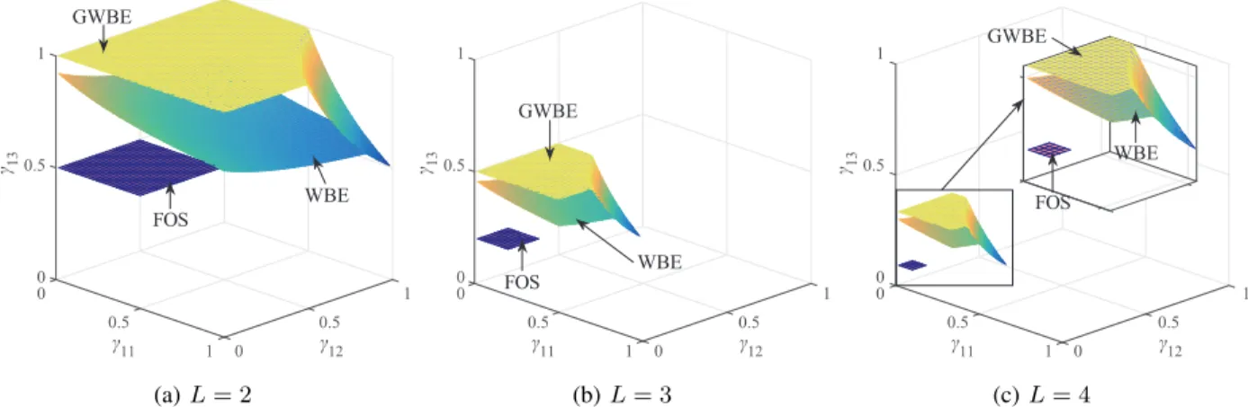
Fig. 2. The upper surface boundary of the capacity regions versus the SINR requirements for the three designs with (a)L= 2, (b)L= 3, and (c)L= 4.
Lemma 3:To satisfy the SINR requirements of all the users in a multi-cell multiuser massive MIMO network using the WBE design, the per-cell capacity region is given by
K X j=1 γij 1 +γij ≤min τ L, κ L+ (1−κ)γMAX i 1 +γMAX i , (23) where κ= ρ21 ijlk = (KK−−1)ττ .
Proof: Please refer to Appendix C.
Comparing (23) with (16), we point out that the WBE design imposes an additional restriction on the per-cell capacity region. Due to this restriction, the per-cell capacity region of the WBE design is smaller than that of our GWBE design.
Using the procedure described in Section III-C, we derive the minimum M required by Ulk
for the WBE design as
Mlk,WBEMIN = P m,nβlkmPmn+σw2 1−µ αµ P p,q Ξ2 lkpβlkpPpq+ P r,s Ξ2 lkrβlkrPrs κ −βlklPlk !, (24)
where Ppq is the transmit power for Upq, where Upq ∈ UsWBEpq , and Prs is the transmit power for
Urs, where Urs ∈U¯sWBEpq . Accordingly, we obtain the minimumM for the network with the WBE
design as MWBEMIN = max1≤l≤L,1≤k≤K{Mlk,MINWBE}. The comparison between MWBEMIN and MGWBEMIN will be provided in Section V-B.
B. Finite Orthogonal Set (FOS) Design
In the FOS design [1, 15], the first τ users in each cell are assigned the uniqueτ orthogonal pilot sequences. Then the remaining K −τ users in the same cell are repeatedly assigned the
same pilot sequences. Given this assignment strategy, the pilot sequence allocated to Ulk is used
by at least L−1 users in the network. We denote UFOS
slk as the group of users that are assigned
the same pilot sequence as Ulk. It is noteworthy that the correlation coefficient between different
pilot sequences is always zero. Therefore, only the users with the same pilot sequence contribute to pilot contamination. The transmit power for Ulk is given by Plk= α1+γlkγlklk.
We next present the per-cell capacity region of the FOS pilot design in the following Lemma.
Lemma 4:To satisfy the SINR requirements of all the users in a multi-cell multiuser massive MIMO network using the FOS design, the per-cell capacity region is given by
K X i=1 γij 1 +γij ≤min τ L, 1 L . (25)
Proof: We obtain (25) by following the procedure outlined in Appendix C.
We conclude that the per-cell capacity region of the FOS design is reduced relative to that of our GWBE design, by comparing (25) with (16). We further find that the minimum M for the network with the FOS design is given by MMIN
FOS = max1≤l≤L,1≤k≤K{Mlk,MINFOS}, where M MIN lk,FOS is obtained as Mlk,MINFOS= P m,nβlkmPmn+σ 2 w 1−µ µ P i,j Ξ2 lkiβlkiPij αij −βlklPlk (26)
with Pij denoting the transmit power for Uij and Uij ∈ UsFOSij . We will compare M
MIN FOS with
MMIN
GWBE in Section V-B.
V. NUMERICAL RESULTS
In this section, we provide numerical results to demonstrate the advantages of using the proposed capacity-achieving GWBE pilot sequence design over existing pilot sequence designs, namely, the WBE and FOS designs.
A. Performance Comparison with Infinite Antennas
In this subsection, we assume that M is infinite and compare the capacity region of the three designs. We also examine the impact of increasing K, varying SINR requirements, and increasing L on the network performance. Throughout this section we consider that the length of pilot sequence is τ = 3. The results in this subsection are generated by using (16), (23), and (25), for the GWBE, WBE, and FOS designs respectively.
K 4 6 8 10 12 14 γ M A X i 0.1 0.2 0.3 0.4 0.5 0.6 0.7 0.8 GWBE WBE FOS
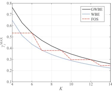
Fig. 3. The per-cell maximum permitted SINR requirement versus the number of per-cell users for the three designs withL= 2 andτ = 3.
We first consider the multiuser massive MIMO network with L = 2, L = 3, and L = 4, where each cell has K = 4 users. The SINR requirements in each cell are chosen as γi =
[γi1, γi2, γi3,0.20], where i∈ {2,3,4}. Fig. 2 depicts the upper surface boundary of the per-cell
capacity region of the three designs. We observe that the proposed GWBE pilot design achieves a larger per-cell capacity region than the WBE and FOS designs. Importantly, this observation is valid for different values of L. This indicates that the proposed GWBE design is more likely to fulfill a diverse set of SINR requirements of the users.
We next examine the impact of increasing K on the maximum permitted SINR require-ment in a cell, γMAX
i . Fig. 3 depicts γMAXi versus K for the three designs. In this figure, we
consider L = 2 and the same SINR requirements for the users in two cells given by γγγi =
[γi1, . . . , γi3, γi4, . . . , γiK], wherei∈ {1,2},γi1 =γi2 =γi3 =γ, andγi4 =. . .=γiK =γ/3. As
such, we have γMAX
i =γ. We first see that increasing K decreasesγiMAX. For example, when K
increases from4to14,γMAX
i of our GWBE design decreases from 0.76 to 0.26. This is due to the
fact that increasing K causes more interference and thus lowers the maximum permitted SINR. Second, we see that the FOS design behaves differently from other designs as K increases. For example, when K increases from 4 to 6 and from 7 to 9, γMAX
i remains constant. This can be
explained by the pilot sequence assignment strategy in the FOS design. Since onlyτ orthogonal pilot sequences are available in the FOS design,γMAX
10-2 10-1 100 101 10-1 100 γ M A X i GWBE WBE FOS ω
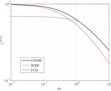
Fig. 4. The per-cell maximum permitted SINR requirement versusωfor the three designs withL= 2andK= 5.
multiple of τ = 3, e.g., K >6 and K >9.
We now evaluate the impact of increasing the individual SINR requirement on γMAX
i . In this
evaluation, we consider L = 2, K = 5, and the same SINR requirements of the users in the two cells given by γγγi = [γ, γ, γ, ωγ, ωγ], where i ∈ {1,2} and 10−2 ≤ ω ≤101. Fig. 4 depicts
γMAX
i versusω for the three designs. We first find that our GWBE design outperforms the FOS
design across the whole range ofω, and outperforms the WBE design in the low and mediumω
regime. When ω >100, our GWBE design exhibits the same performance as the WBE design.
This is due to the fact that the upper surface boundary of the per-cell capacity region of the GWBE and WBE designs overlap in this regime. Consequently, the performance of two designs is equivalent to each other. We also find that the FOS design outperforms the WBE design in the low ω regime, since the FOS design incurs less interference than the WBE design in this regime.
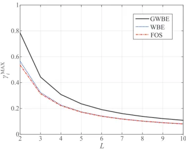
Finally, we focus on the impact of increasing L on γMAX
i . In particular, we consider an
L-cell network with K = 5 and the SINR requirements given by γγγi = [γ, γ, γ/3, γ/3, γ/3],
where i ∈ {1, . . . , L}. Fig. 5 depicts γMAX
i versus L for the three designs. We first observe
that increasing L decreases γiMAX. For example, when L increases from 2 to 10, γiMAX of our GWBE design decreases from 0.78 to 0.11. This can be explained by the decrease in the per-cell capacity region, as depicted in Fig. 2. Second, we observe that the our GWBE design provides higher γMAX
L 2 3 4 5 6 7 8 9 10 0 0.2 0.4 0.6 0.8 1 γ M A X i GWBE WBE FOS
Fig. 5. The per-cell maximum permitted SINR requirement versus the number of cells for the three designs withK= 5. B. Performance Comparison with Finite Antennas
In this subsection, we assume that M is finite and compare the performance achieved by the three designs. Throughout this subsection, we consider L = 2, τ = 3, and K = 4. We also consider that the SINR requirements in the two cells are given by γγγ1 = [0.91,0.74,0.64,0.23]
andγγγ2 = [0.94,0.82,0.45,0.20]. We note that the considered SINR requirements remain within
the capacity region of our GWBE design but lie outside the capacity region of the WBE and FOS designs. This implies that our GWBE design supports a more diverse range of SINR requirements than other designs. In addition, we note that an important criterion in designing the capacity-achieving GWBE pilot sequences is that γˆlk > γlk needs be chosen to satisfy (14)
with equality, as clarified in Section III. As such, we choose γγˆˆˆγ1 = [0.92,0.75,0.65,0.24] and
ˆ
γˆγγˆ2 = [0.95,0.85,0.50,0.29] for the two cells. Furthermore, we assume that pijβijl= 0.9, where
i 6= l. For clarity, the simulation parameters and the pilot sequences for the three designs are summarized in Table I.
Fig. 6 depicts θlk,M versusM for the three designs. In this figure, we only consider θlk,M of
four users, namely, U11, U14, U22, and U23, to avoid visual cluttering4. The analytical curves for
the three designs are generated from (11), while the Monte Carlo simulation points for the three
4
We clarify that the behavior of the unconsidered users, i.e., U12, U13, U21, and U24, is similar to that of the four users
TABLE I
SIMULATIONPARAMETERS ANDPILOTSEQUENCES
GWBE WBE FOS
Common Parameters σ2
z=σw2= 1,L= 2,τ= 3,K= 4,Ktot= 8,γγγ1= [0.91,0.74,0.64,0.23], γγγ2= [0.94,0.82,0.45,0.10]
βlkm= 1, wherel=mandβlkm= 0.9, wherel6=m
Transmit Power αlkˆγlk/(1 + ˆγlk)∗ αlkγlk/(1 +γlk) αlkγlk/(1 +γlk) Pilot Sequences S1= 1 −0.0845 −0.1075 0.2574 0 0.9964 −0.2202 0.5274 0 0 0.9695 0.8097 S1= 1 −0.3333 −0.3333 0.3333 0 0.9428 −0.4714 0.4714 0 0 0.8165 0.8165 S1= 1 0 0 1 0 1 0 0 0 0 1 0 S2= 1 −0.0500 −0.1182 0.1867 0 0.9988 −0.2186 0.3453 0 0 0.9686 0.9197 S2=S1 S2=S1 ∗γγγˆ 1= [0.92,0.75,0.65,0.24],γγˆγ2= [0.95,0.85,0.50,0.29] M 0 50 100 150 200 250 300 θ lk,M 0 0.2 0.4 0.6 0.8 1 1.2 1.4 U11 U14 (a)θ11,M andθ14,M M 0 50 100 150 200 250 300 θ lk,M 0 0.2 0.4 0.6 0.8 1 1.2 1.4 U 22 U 23 (b)θ22,M andθ23,M
Fig. 6. The achievable SINR versus the number of antennas for the three designs.
designs are obtained by averaging (10) over 1,000 channel realizations. It is clearly seen that the Monte Carlo simulation points precisely agree with the analytical curves, which demonstrates the accuracy of (11). We first see from Fig. 6 that our GWBE design is the only design that satisfies the SINR requirements of all the users in the network. If the WBE design or the FOS design is adopted, the SINR requirements of only a few users are satisfied. Second, we see that our GWBE design does not always provide the highest achievable SINR for each user.
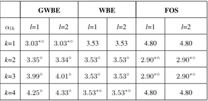
TABLE II
SUMMARY OF THEVALUE OFαlk
GWBE WBE FOS
αlk l=1 l=2 l=1 l=2 l=1 l=2 k=1 3.03∗◦ 3.03∗◦ 3.53 3.53 4.80 4.80 k=2 3.35◦ 3.34◦ 3.53◦ 3.53◦ 2.90∗◦ 2.90∗◦ k=3 3.99◦ 4.01◦ 3.53◦ 3.53◦ 2.90∗◦ 2.90∗◦ k=4 4.25◦ 4.33◦ 3.53∗◦ 3.53∗◦ 4.80 4.80 ∗
indicates the highest achievable SINR;◦indicates thatθlk≥γlk.
This can be explained by αlk for Ulk of the three designs as follows: As indicated by (11), an
increase in αlk gives a lower achievable SINR. The value of αlk of the eight users for the three
designs are summarized in Table II. Using Fig. 6 together with Table II, we find that the highest achievable SINR is attained for the lowestαlk. Furthermore, we point out that the WBE and FOS
designs provide a higher achievable SINR for some users than our GWBE design. However, the higher achievable SINR is provided at the expense of degrading the achievable SINR of other users. As such, the user with the degraded achievable SINR cannot satisfy the predefined SINR requirements even as M → ∞. Therefore, it is worth highlighting that the practical advantage of our GWBE design lies in its ability of fulfilling the SINR requirements of all the users in the network.
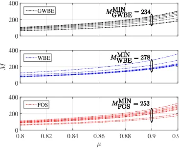
Finally, we find the minimum number of antennas at BSs to achieve the satisfactory network performance. In this evaluation, we consider the same parameters as given in Table I. Fig. 7 depicts the minimum number of antennas required by the eight users to achieve the SINR requirement given by µθlk,∞ for the three designs. The minimum number of antennas clarified
in the figure, i.e., MMIN
GWBE = 234, MWBEMIN = 278, and MFOSMIN = 253, are determined by setting
µ = 0.9 in (22), (24), and (26), respectively. Comparing MMIN
GWBE with MWBEMIN and MFOSMIN, we find that a key benefit of our GWBE design is that it requires the lowest number of antennas. This benefit becomes particularly compelling when considering the fact that our GWBE design achieves the SINR requirements of all the users in the network, as revealed by Fig. 6 and Table II.
0 200 400 MGWBEMIN = 234 MGWBEMIN = 234 MGWBEMIN = 234 MGWBEMIN = 234 MGWBEMIN = 234 MGWBEMIN = 234 MGWBEMIN = 234 MGWBEMIN = 234 GWBE M 0 200 400 MWBEMIN = 278 MWBEMIN = 278 MWBEMIN = 278 MWBEMIN = 278 MWBEMIN = 278 MWBEMIN = 278 MWBEMIN = 278 MWBEMIN = 278 WBE µ 0.8 0.82 0.84 0.86 0.88 0.9 0.92 0 200 400 MFOSMIN= 253 MFOSMIN= 253 MFOSMIN= 253 MFOSMIN= 253 MFOSMIN= 253 MFOSMIN= 253 MFOSMIN= 253 MFOSMIN= 253 FOS
Fig. 7. The number of antennas required at BSs versus the performance satisfaction index for the three designs.
VI. CONCLUSION
We proposed a novel GWBE pilot sequence design for multi-cell multiuser massive MIMO networks. We first derived closed-form expressions for the user capacity and the capacity region of the network. Based on them, we developed a new algorithm to generate capacity-achieving pilot sequences which always fulfill the SINR requirements of all users throughout the network. We further conducted analytical and numerical performance comparison of our proposed GWBE design with the existing WBE and FOS designs. The comparison demonstrated that our GWBE design achieves a larger capacity region and supports a more diverse range of SINR requirements than the WBE and FOS designs. In addition, we confirmed that our GWBE design needs a lower number of antennas at BSs than the WBE and FOS designs to meet the predefined SINR requirements. Our results offer a set of practically valuable guidelines for next-generation wireless infrastructure providers to efficiently design pilot sequences such that superior performance is achieved without utilizing unnecessary antennas.
APPENDIXA PROOF OFLEMMA1
In this appendix, we detail the derivation of a channel-independent expression for the achiev-able SINR, given by (11), based on the channel-dependent expression for the achievachiev-able SINR
given by (10). First, we calculate the mathematical expectation, E|gmn lk | 2 , in the denominator of (10). Using (5), we rewrite E|gmn lk | 2 as E|glkmn| 2 =E h hHlkmtmn 2i =E hH lkmhˆmnm √ M αmn 2 . (27)
Using the LS channel estimate given by (3) and defining ˘gijm ,Ξijmhijm, PL
i=1 PK j=1 , P i,j, we expand h H lkhˆmnm 2 in (27) as h H lkmhˆmnm 2 = hHlkm X i,j ρijmn˘gijm+STmnzm ! 2 = X p,q ρpqmnhHlkm˘gpqm+hHlkmSTmnzm !H × X r,s ρrsmnhHlkmgrsm˘ +hHlkmSTmnzm ! , =X p,q X r,s ρpqmnρrsmn˘gHpqmhlkmhHlkm˘grsm+ X p,q ρpqmn˘gHpqmhlkmhHlkmSTmnzm +zHmSmn X r,s ρrsmnhlkmhHlkm˘grsm+zHmSmnhlkmhHlkmS T mnzm. (28) Defining P p,q P r,s, P p,q
r,s, we calculate the expectation of (28) as
E h H lkmhˆmnm 2 =E X p,q r,s ρpqmnρrsmn˘gHpqmhlkmhHlkm˘grsm + 0 + 0 +E zHmSmnhlkmhHlkmS T mnzm , =ρ2lkmnE˘glkmH hlkmhHlkm˘glkm + X p=r6=l q=s6=k ρ2pqmnEtr ˘gHpqmhlkmhHlkm˘gpqm +Etr zHmSmnhlkmhHlkmS T mnzm . (29) We observe that hH
lkmhlkm in (29) has a gamma distribution with the shape parameter M and
the scale parameter 1 given by Γ (M,1). Therefore, we find that E˘gH
lkmhlkmhHlkm˘glkm in (29) is Ξ2lkmM(M + 1). This simplifies (29) as E h H lkmhˆmnm 2 =ρ2lkmnΞ2lkmM(M + 1) + X p=r6=l q=s6=k ρ2pqmnEtr hlkmhHlkm˘gpqm˘gHpqm +Etr hlkmhHlkmS T mnz H mz H mSmn ,
=ρ2lkmnΞ2lkm M2+M+M L X p=r6=l K X q=s6=k ρ2pqmnΞ2pqm+M σz2, =M2ρ2lkmnΞ2lkm+M αmn. (30)
Substituting (30) into (27), we obtain E|gmnlk |2
= (M ρ2lkmnΞ2lkm+αmn)/αmn.
We now find the variance of glk = hHlkltlk. We observe that the variance of the gamma
distributed glk is given by varhHlklˆtlk =var " h√lklHhˆlkl M αlk # =E hlklHhˆlkl−E h hlklHhˆlkl i √ M αlk 2 = M αlk √ M αlk 2 = 1. (31)
Finally, substituting (30) and (31) into (10), the achievable SINR, θlk,M, is derived as
θlk,M = E h h√lklHhˆlkl M αlk i2 βlklPlk βlklPlk+ P m,n6=l,k M ρ2 lkmnΞ2lkm+αmn αmn βlkmPmn+σw2 , = M √ M αlk 2 βlklPlk βlklPlk+ P m,n6=l,k M ρ2 lkmnΞ2lkm+αmn αmn βlkmPmn+σw2 , = βlklPlk αlk M " P m,n6=l,k M ρ2 lkmnΞ 2 lkm αmn βlkmPmn+ ¯Plk #, (32)
where P¯lk =Pm,nβlkmPmn+σw2. Simplifying (32) we obtain the desired result in (11).
APPENDIX B
PROOF OF PROPOSITION1
In this appendix, we determine the user capacity of the multi-cell multiuser massive MIMO network. From (12), we obtain the following in accordance with the rule of uplink power control
θlk,∞ ≥θˆlk,∞ = Plk αlkPm,n ρ2 lkmnPmn αmn −Plk , (33) = Plk αlktr(sTlkSPASTslk) ,
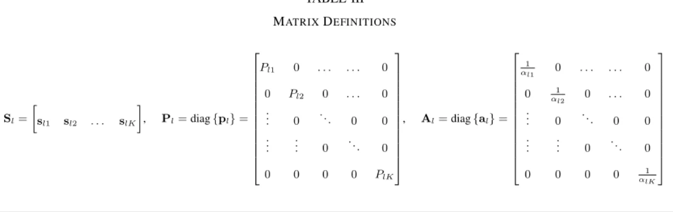
whereS,P, andAare block matrices given byS= [S1, . . . ,Sl, . . . ,SL],P=diag[P1, . . . ,Pl, . . . ,PL],
and A = diag[A1, . . . ,Al, . . . ,AL], respectively. The sub-blocks Sl, Pl, and Al are the pilot
TABLE III MATRIXDEFINITIONS Sl= sl1 sl2 . . . slK , Pl=diag{pl}= Pl1 0 . . . 0 0 Pl2 0 . . . 0 .. . 0 . .. 0 0 .. . ... 0 . .. 0 0 0 0 0 PlK , Al=diag{al}= 1 αl1 0 . . . 0 0 1 αl2 0 . . . 0 .. . 0 . .. 0 0 .. . ... 0 . .. 0 0 0 0 0 1 αlK
BSl forK same-cell users, and a diagonal matrix consisting of the inverse of parameterαlk for
K same-cell users, respectively. Sl, Pl, and Al are given by Table III.
We next obtain the following expression
X i,j 1 + ˆθij,∞ ˆ θij,∞ =X i,j " 1 + αijtr sijSPAS Ts ij Pij # , =tr P−1A−1STSPASTS. (34) We next define PA ,Z and STS,R
S. Using matrix definitions in Table III, we expand (34)
as X i,j 1 + ˆθij,∞ ˆ θij,∞ =tr Z−1RSZRS , =Ktot+ X p,q X r,s | {z } p>r,q>s αrsPpq αpqPrs +αpqPrs αrsPpq ρ2pqrs, ≥Ktot+ X p,q X r,s | {z } p>r,q>s 2ρ2pqrs, ≥tr(RSRS). (35)
Since RS is a symmetric matrix, its eigen decomposition is given by QΛQT, where Q is a unitary matrix and Λ is a Ktot×Ktot diagonal matrix. We note that the first τ elements in the main diagonal of Λ are the eigenvalues of RS and the rest are zero. Accordingly, we obtain the
following tr QΛQTQΛQT=tr Λ2i= Ktot X i=1 λ2i = 1 τ τ X i=1 λi !2 = 1 τK 2 tot. (36)
Substituting (36) into (35), we obtain X i,j 1 + ˆθij,∞ ˆ θij,∞ ≥ 1 τK 2 tot. (37)
An important requirement in the multi-cell multiuser massive MIMO network is that the SINR requirement of a user cannot exceed its maximum achievable SINR with infinite M, i.e.,
γij ≤θˆij,∞ ≤θij,∞. As such, we find that X i,j 1 + ˆθij,∞ ˆ θij,∞ ≤X i,j 1 +γij γij (38) always holds true. Using the inequality in (38) together with (37), we obtain the desired result in (13).
APPENDIX C PROOF OFLEMMA3
In this appendix, we derive the per-cell capacity region of the WBE design. Substituting
αij =α into (33), we obtain the asymptotic achievable SINR of the WBE design as
ˆ θlk,∞ = Plk PL m=1 PK n=1ρ 2 lkmnPmn−Plk , (39)
Using Plk = 1+γαγlklk and θˆij,∞ ≥γij, we rewrite (39) as
ˆ θlk,∞ = αγlk 1+γlk αPL m=1 PK n=1 ρ2 lkmnγmn 1+γmn − αγlk 1+γlk = γlk 1+γlk P p,q γpq 1+γpq + P r,s ρ2 lkrsγrs 1+γrs − γlk 1+γlk ≥γlk, (40)
whereγp,q is the SINR requirement of Upq using the pilot sequencespq |Upq ∈ UsWBEpq and γr,s is
the SINR requirement of Urs using the pilot sequence srs |Urs ∈U¯sWBEpq . Simplifying (40) gives X p,q γpq 1 +γpq + 1 κ X r,s γrs 1 +γrs ≤1. (41)
Therefore, the per-cell user capacity region is given by
γpq 1 +γpq + 1 κ K X s=1 γps 1 +γps − γpq 1 +γpq ! ≤ 1 L. (42)
Further simplifying (42) we obtain
K X s=1 γps 1 +γps ≤ κ L+ (1−κ)γpq 1 +γpq . (43)
We clarify that (41) represents the capacity region of the WBE design. Moreover, the condition for meeting the SINR requirements of all the users given by (16) needs to be fulfilled, regardless of the pilot sequence design. Jointly considering (43) and (16), we obtain the per-cell capacity region of the WBE design, as given by (23), which completes the proof.
REFERENCES
[1] T. Marzetta, “Noncooperative cellular wireless with unlimited numbers of base station antennas,”IEEE Trans. Wireless Commun., vol. 9, no. 11, pp. 3590–3600, Nov. 2010.
[2] F. Boccardi, R. Heath, A. Lozano, T. Marzetta, and P. Popovski, “Five disruptive technology directions for 5G,”IEEE Commun. Mag., vol. 52, no. 2, pp. 74–80, Feb. 2014.
[3] N. Yang, L. Wang, G. Geraci, M. Elkashlan, J. Yuan, and M. Di Renzo, “Safeguarding 5G wireless communication networks using physical layer security,”IEEE Commun. Mag., vol. 53, no. 4, pp. 20–27, Apr. 2015.
[4] E. Larsson, O. Edfors, F. Tufvesson, and T. Marzetta, “Massive MIMO for next generation wireless systems,” IEEE Commun. Mag., vol. 52, no. 2, pp. 186–195, Feb. 2014.
[5] A. Yang, Y. Jing, C. Xing, Z. Fei, and J. Kuang, “Performance analysis and location optimization for massive MIMO systems with circularly distributed antennas,”IEEE Trans. Wireless Commun., vol. 14, no. 10, pp. 5659–5671, Oct. 2015. [6] F. Rusek, D. Persson, B. K. Lau, E. Larsson, T. Marzetta, O. Edfors, and F. Tufvesson, “Scaling up MIMO: Opportunities
and challenges with very large arrays,”IEEE Signal Process. Mag., vol. 30, no. 1, pp. 40–60, Jan. 2013.
[7] L. Lu, G. Y. Li, A. L. Swindlehurst, A. Ashikhmin, and Z. Rui, “An overview of massive MIMO: Benefits and challenges,”
IEEE J. Sel. Topics Signal Process., vol. 8, no. 5, pp. 742–758, Oct. 2014.
[8] Q. Zhang, S. Jin, M. McKay, D. Morales-Jimenez, and H. Zhu, “Power allocation schemes for multicell massive MIMO systems,”IEEE Trans. Wireless Commun., vol. 14, no. 11, pp. 5941–5955, Nov. 2015.
[9] X. Zhu, L. Dai, and Z. Wang, “Graph coloring based pilot allocation to mitigate pilot contamination for multi-cell massive MIMO systems,”IEEE Commun. Lett., vol. 19, no. 10, pp. 1842–1845, Oct. 2015.
[10] A. Khansefid and H. Minn, “On channel estimation for massive MIMO with pilot contamination,”IEEE Commun. Lett., vol. 19, no. 9, pp. 1660–1663, Sep. 2015.
[11] A. Khansefid and H. Minn, “Achievable downlink rates of MRC and ZF precoders in massive MIMO with uplink and downlink pilot contamination,”IEEE Trans. Commun., accepted to appear.
[12] F. Fernandes, A. Ashikhmin, and T. Marzetta, “Inter-cell interference in noncooperative TDD large scale antenna systems,”
IEEE J. Sel. Areas Commun., vol. 31, no. 2, pp. 192–201, Feb. 2013.
[13] X. Zhu, Z. Wang, L. Dai, and C. Qian, “Smart pilot assignment for massive MIMO,”IEEE Commun. Lett., vol. 19, no. 9, pp. 1644–1647, Sep. 2015.
[14] H. Ahmadi, A. Farhang, N. Marchetti, and A. MacKenzie, “A game theoretic approach for pilot contamination avoidance in massive MIMO,”IEEE Wireless Commun. Lett., accepted to appear.
[15] J. Jose, A. Ashikhmin, T. Marzetta, and S. Vishwanath, “Pilot contamination and precoding in multi-cell TDD systems,”
IEEE Trans. Wireless Commun., vol. 10, no. 8, pp. 2640–2651, Aug. 2011.
[16] H. Yin, D. Gesbert, M. Filippou, and Y. Liu, “A coordinated approach to channel estimation in large-scale multiple-antenna systems,”IEEE J. Sel. Areas Commun., vol. 31, no. 2, pp. 264–273, Feb. 2013.
[17] R. Muller, L. Cottatellucci, and M. Vehkapera, “Blind pilot decontamination,”IEEE J. Sel. Topics Signal Process., vol. 8, no. 5, pp. 773–786, Oct. 2014.
[18] H. Wang, W. Zhang, Y. Liu, Q. Xu, and P. Pan, “On design of non-orthogonal pilot signals for a multi-cell massive MIMO system,”IEEE Wireless Commun. Lett., vol. 4, no. 2, pp. 129–132, Apr. 2015.
[19] J. So, D. Kim, Y. Lee, and Y. Sung, “Pilot signal design for massive MIMO systems: A received signal-to-noise-ratio-based approach,”IEEE Signal Process. Lett., vol. 22, no. 5, pp. 549–553, May 2015.
[20] M. Jung, Y. Kim, J. Lee, and S. Choi, “Optimal number of users in zero-forcing based multiuser MIMO systems with large number of antennas,”J. Commun. and Networks, vol. 15, no. 4, pp. 362–369, Aug. 2013.
[21] C. Zhong, G. Zheng, and K.-K. Wong, “Feasibility conditions of linear multiuser MIMO systems in the asymptotic regime,”
IEEE Commun. Lett., vol. 11, no. 12, pp. 979–981, Dec. 2007.
[22] J.-C. Shen, J. Zhang, and K. Letaief, “Downlink user capacity of massive MIMO under pilot contamination,”IEEE Trans. Wireless Commun., vol. 14, no. 6, pp. 3183–3193, June 2015.
[23] P. Viswanath, V. Anantharam, and D. Tse, “Optimal sequences, power control, and user capacity of synchronous CDMA systems with linear MMSE multiuser receivers,” IEEE Trans. Inf. Theory, vol. 45, no. 6, pp. 1968–1983, Sep. 1999. [24] P. Viswanath and V. Anantharam, “Optimal sequences and sum capacity of synchronous CDMA systems,” IEEE Trans.
Inf. Theory, vol. 45, no. 6, pp. 1984–1991, Sep. 1999.
[25] S. Ulukus and R. Yates, “Iterative construction of optimum signature sequence sets in synchronous CDMA systems,”IEEE Trans. Inf. Theory, vol. 47, no. 5, pp. 1989–1998, July 2001.
[26] J. Tropp, I. Dhillon, and R. Heath, “Finite-step algorithms for constructing optimal CDMA signature sequences,” IEEE Trans. Inf. Theory, vol. 50, no. 11, pp. 2916–2921, Nov. 2004.
[27] S. Kishore, L. Greenstein, H. Poor, and S. Schwartz, “Uplink user capacity in a multicell CDMA system with hotspot microcells,” IEEE Trans. Wireless Commun., vol. 5, no. 6, pp. 1333–1342, June 2006.
[28] X. Gao, O. Edfors, F. Rusek, and F. Tufvesson, “Massive MIMO performance evaluation based on measured propagation data,”IEEE Trans. Wireless Commun., vol. 14, no. 7, pp. 3899–3911, July 2015.
[29] X. Yan, H. Yin, M. Xia, and G. Wei, “Pilot sequences allocation in TDD massive MIMO systems,” inProc. IEEE WCNC, New Orleans, LA, Mar. 2015, pp. 1488–1493.
[30] Z. Kan, O. Suling, and X. Yin., “Massive MIMO channel models: A survey,”Int. J. Antennas Propag., vol. 2014, pp. 1–10, June 2014.
[31] T. Narasimhan and A. Chockalingam, “Channel hardening-exploiting message passing (CHEMP) receiver in large-scale MIMO systems,”IEEE J. Sel. Topics Signal Process., vol. 8, no. 5, pp. 847–860, Oct. 2014.
[32] G. H. Hardy, J. E. Littlewood, and G. P´olya,Inequalities. Cambridge: Cambridge University Press, 1954.
[33] L. Welch, “Lower bounds on the maximum cross correlation of signals (corresp.),”IEEE Trans. Inf. Theory, vol. 20, no. 3, pp. 397–399, May 1974.