The University of Akron
IdeaExchange@UAkron
Honors Research Projects
The Dr. Gary B. and Pamela S. Williams Honors
College
Spring 2016
The Smart Hard Hat
Darcy Fyffe
University of Akron, [email protected]
Connor Langenderfer
University of Akron, [email protected]
Charlton Johns
University of Akron, [email protected]
Please take a moment to share how this work helps you
through this survey
. Your feedback will be
important as we plan further development of our repository.
Follow this and additional works at:
http://ideaexchange.uakron.edu/honors_research_projects
Part of the
Biomedical Devices and Instrumentation Commons
This Honors Research Project is brought to you for free and open access by The Dr. Gary B. and Pamela S. Williams Honors College at IdeaExchange@UAkron, the institutional repository of The University of Akron in Akron, Ohio, USA. It has been accepted for inclusion in Honors Research Projects by an authorized administrator of
IdeaExchange@UAkron. For more information, please [email protected], [email protected].
Recommended Citation
Fyffe, Darcy; Langenderfer, Connor; and Johns, Charlton, "The Smart Hard Hat" (2016).Honors Research Projects. 267.
BME Senior Design 4800:492
Honors Research Project Report
The Smart Hard Hat Team
Darcy Fyffe, Charlton Johns, and Connor Langenderfer (Additional Team Members: Dominic Conte and Ben DeShon)
1
Honors Research Project Approvals
Reader 1 (Dr. Bing Yu) Date
Reader 2 (Dr. Rouzbeh Amini) Date
Project Sponsor (Dr. James Keszenheimer) Date
Honors Advisor (Dr. Mary Verstraete) Date
2
Introduction
Among the most important factors for any company is employee safety. Take, for example, one of the world’s largest and most international companies, General Electric (GE). GE has been around for over 130 years, and yet in the 2014 Annual report GE still discusses employee safety as one of its largest and most important goals [1]. With safety being a top priority for a top company it is easy to see that safety should be an important corporate pillar for any size business. Why? Because no matter the corporation, business segment, or location, a company cannot run without its most valuable asset: its employees. Millions of laborers around the globe go to work every day relying on basic safety devices, such as harnesses and steel-toed boots, to protect them. It is becoming essential that modern technological advances contribute to enhancing the safety of our workforce. It is with this thought that the Smart Hard Hat team set forth to improve the safety of workers everywhere by creating a personal protective equipment (PPE) device to monitor worker biometrics so as to prevent the effects of overexertion before potential injury can occur. Team Smart Hard Hat strived to do the following:
“Our mission is to design and develop a protective helmet that will satisfy the health and safety needs of our clients and consumer base, as well as our own personal standards of excellence. Our goal is to develop and construct a functioning protective headgear product that keeps the safety of the end user at the forefront of the design. In doing so, we will improve overall safety for indoor and outdoor workers by monitoring biometrics in order to reduce overexertion, survey cranial impacts, and ultimately decrease workplace injuries.”
Our proposed Smart Hard Hat device is intended for use by indoor and outdoor laborers to monitor biometrics as they perform their occupational duties. The device combines a variety of sensors and components, along with a central processing board to deliver immediate feedback alerts to both the worker and their supervisor if dangerous situations have occurred. By adding layers of technology, the Smart Hard Hat effectively increases protection for the worker from the hidden dangers of the job site, such as overexertion, heat exhaustion, concussive impacts and confined spaces. In a market dominated by brands such as 3M, Honeywell and MSA, the Smart Hard Hat provides a fresh approach to the Environmental Health & Safety (EHS) monitoring available to the most basic laborers. Keeping costs reasonable will ensure that this device is available to all levels of physical laborers. This project was not only meant to explore the hidden dangers inherent in any physically demanding field of labor, but to create a concept device that combats these dangers, which will lead to a more productive, and safer workforce.
Background Information
Approximately 6.5 million construction workers are at risk everyday of falling victim to hidden dangers innate to their jobs. A need exists to be able to monitor the worker's biometric signals so as to prevent the effects of overexertion before potential injury can occur. According to a 2012 white paper by the Occupational Safety and Health Administration (OSHA), over 4,500 workers lose their lives, and more than 4 million are seriously injured each year [2]. The Liberty Mutual Safety Index (2016) reported that the leading cause of injury among private sector workers in 2013 was overexertion, accounting for approximately 24% of all workplace injuries [3] (Figure 1).
3 Figure 1. Top 10 Causes of Disabling Injuries in 2010. Adapted from Liberty Mutual Research Institute, 2016 [3]
Should the Smart Hard Hat device be expanded upon and brought to market, it would provide a myriad of benefits to many parties involved in the industry. Workers would experience a safer work environment, and avoid high amounts of physical, emotional, and financial hardship associated with injury, while employers will avoid many direct and indirect costs associated with worker injuries. According to the Liberty Mutual Workplace Safety Index (2016), the most disabling
workplace injuries and illnesses in 2013 amounted to $61.88 billion in direct costs, 24% of which is a direct result of overexertion [3], costing approximately $15.08 billion. Increased worker production and safety will contribute to a decrease in indirect costs to the employers including: [2]
• Wages paid to injured workers during absence • Time lost through reduced or light duty staff
• Administrative time spent by supervisors following injuries • Employee training and replacement costs
• Lost productivity related to new employee training and accommodation of injured
employees
Additionally, insurance companies will experience decreases in the magnitude of
compensation benefits. The National Academy of Social Insurance reports that in 2012, workers’ compensation covered around 128 million workers, providing approximately $62 billion in benefits, a 1.3 percent increase from 2011 [4].
Based on market research conducted by Grandview Research, the global PPE market was valued at $34 billion in 2014, and is expected to grow at a 7.2% compound annual growth rate to $62.45 billion by 2022 (Figure 2) [5]. This growth is expected to result from increased demand for construction and industrial production. As this downstream activity increases, employers will
purchase PPE in higher demands to comply with workplace safety regulations. Additionally, the high economic impact on companies from workplace injuries will further incentivize companies to
4
purchase innovative PPE products that go above and beyond to increase safety. Market research firm Radiant Insights reported that North America emerged as the leading regional market and accounted for 41.2% of total revenue in the industry in 2014. Moreover, the construction industry is anticipated to grow the fastest over the forecast period [6]. A PPE Manufacturing Report generated by IBIS World in 2015 indicates that within the United States, head protection make up approximately 24% of the industry [7].
Figure 2. Projected Growth of Global PPE Market. Adapted from Grandview Research [5]
Competition in this market sector includes the major PPE Manufacturing Companies, 3M Company, MSA Safety Inc., and Honeywell International Inc., which combined hold 57.3% of the market [7]. We also face competition from smaller startup companies that produce innovative biometric monitoring protective equipment. Some existing products already on the market include the LifeBeam’s Smart Bicycle Helmet and Smart Athletic Hat, which measure heart rate via an optical sensor, cadence, and calorie consumption during exercise. The measurement signals are sent wirelessly to the user’s smartphone or fitness watch via Bluetooth [8]. Riddell’s InSite Impact Response Football Helmet is fitted with a series of sensors and electrical components to evaluate the impacts sustained while on the field. In addition to monitoring the force, location, and intensity of the impacts, the helmet transmits alerts wirelessly to a monitor if impact thresholds are exceeded [9]. Schutt’s Smart Football Helmet uses a thermistor to monitor the player’s body temperature and an onboard radio transmits temperature readings in real time to a personal digital assistant (PDA) held on the sidelines [10]. Additionally, a new prototype hard hat product is being developed by Laing O’Rourke that combines a sensor array into an insert for retrofitting into an existing hard hat. This prototype monitors the temperature and heart rate of the worker, GPS location, and external
temperature and humidity of the work environment. It utilizes a vibratory and auditory alert system for the wearer, and email or text message alerts can be sent to other parties [11]. There are also a variety of patents with similar technology and designs as our product, which we must not infringe upon should we bring the Smart Hard Hat to market. These patents are listed in the Engineering Requirements (Appendix A.2). Several of the designs utilize wireless transceivers that display alarms in response to events monitored by protective headgear via the use of biometric sensors. Although
5 the majority of patents have been listed in broad terms, patent #9,082,284 specifically identifies that the device be used to manage hazards on construction sites.
Our product differentiates from the competition by combining the key biometric sensors that can indicate danger to a worker (body temperature, heart rate, and concussive force) into one
product, and transmitting that information through cellular data to a site supervisor using a Global System for Mobile Communication (GSM) board. This method of signal transmission is preferred over Bluetooth due to the long range of signal transmission capable while using GSM. Site supervisors will not need to carry around additional electronic alert equipment, and they will not need to be within wireless Bluetooth range to receive notification that their workers health and safety is in danger. The text message alerts include the worker ID, time, and the biometric threshold that has been exceeded. Additionally, there is an immediate feedback alert to the worker via a LED light on the hat brim, which indicates if a threshold has been exceeded. We concluded that a visual alert display was the optimal method of information transfer to the worker as opposed to auditory or vibratory. This is due to the often loud working conditions of a construction site, as well as manual labor activities (such as using a jackhammer) that would cause the vibratory alert to go unnoticed.
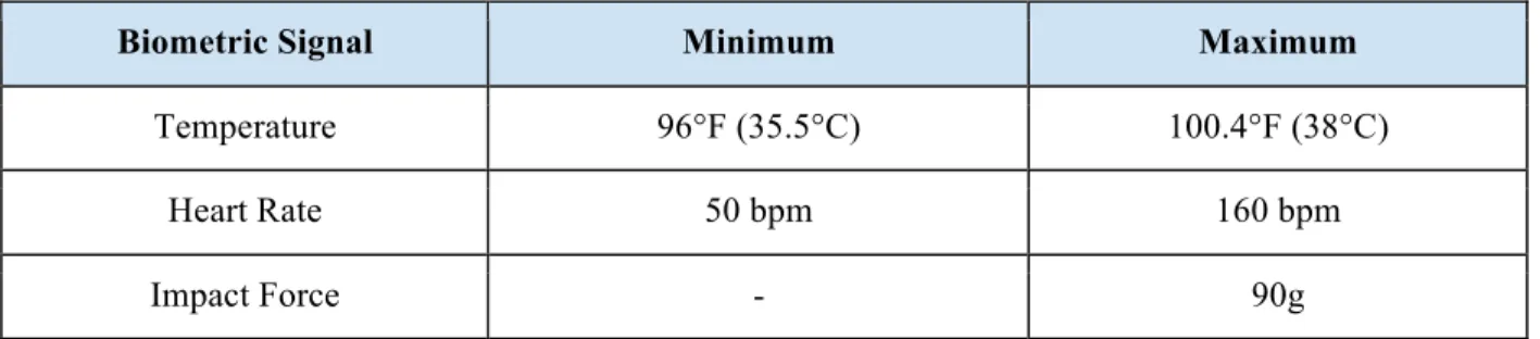
We determined which vital signs were the most important to measure, then researched the OSHA worker safety standards and the biometric limits that the human body can subject itself to before overexertion occurs. We have identified the following biometric thresholds:
Table 1. Biometric Thresholds
Biometric Signal Minimum Maximum
Temperature 96°F (35.5°C) 100.4°F (38°C)
Heart Rate 50 bpm 160 bpm
Impact Force - 90g
The maximum threshold for temperature was selected as 100.4°F. This was based on a recommendation by The American Conference of Governmental Industrial Hygienists as described in Section III, Chapter 4 of the OSHA Technical Manual [12]. It is also the medical standard of body temperature for a fever. Heat stroke typically occurs when the body temperature reaches
approximately 104°F, but the idea is that this device will help to prevent overexertion before it occurs. We have identified a minimum threshold for core temperature to prevent possible
hypothermia as well. Since the body tends to enter hypothermia upon falling below 95°F [13], we set our threshold at 96°F as an alert. We have selected the minimum and maximum heart rate thresholds to be 50 bpm and 160 bpm respectively. The average resting heart rate for adults is typically
between 60-100 bpm [14]. Dropping below 50 bpm can be dangerous and a sign of heart attack or cardiac arrest [15] for individuals that are not trained athletes. The average age of a construction worker in industry is 40.4 years [16], and the average maximum heart rate at that age for a healthy and athletically fit person is approximately 180 bpm [17]. Assuming that construction workers are not in a constant state of athletic exertion, we can lower this threshold to 160 bpm. Heart rates this
6 high can be an indicator of overexertion or a heart attack. Selecting the thresholds of 50 bpm and 160 bpm will provide enough time to alert the worker and their supervisor of possible overexertion or heart arrhythmias in order to follow appropriate safety protocol and reduce the risk of life threatening injuries. An impact acceleration value will lie between the range of 90-100g in order to cause a concussion, with studies tracking the impact forces received in football players who received concussions from head trauma indicating the acceleration force leading to a concussion to be at or above the 90g threshold [18]. As a note, while our hard hat looks to alert the user as accurately as possible, endless variations in head physiology and impact type means that no two head injuries are likely to be the same. An impact to one part of the head can cause trauma, while a separate impact to another region may not. For this reason, our impact force threshold is only meant to be a supplement to make a site foreman aware of head trauma, and is not intended to diagnose any type of head injury. All head injuries sustained on the worksite should be treated by a medical professional, regardless of force intensity.
Project Objectives and Goals
We set a variety of project objectives and goals that we aimed to meet by the completion of this project. First, we worked to develop a hard hat capable of detecting body temperature, heart rate, and impact forces. Additionally, the device should be capable of alerting both the worker and
supervisor if the biometric values fall above or below the set safety thresholds, or if a distress button had been activated. A major aspect of this goal revolved around the research, selection process, and purchasing of sensors and circuitry components. The sensors and their biometric monitoring ability were critical to the overall design of the Smart Hard Hat, and a thorough selection process was of the utmost importance. We verified that these goals had been met by first testing an alpha unit in the form of a breadboard circuit, which confirmed the individual functionality of each component as well as their ability to work in tandem through an Arduino Uno microcontroller board. Once the accuracy and communicative ability between the components had been verified, the next step was to
incorporate them within the shell of a hard hat. Unfortunately, we were unable to reach this portion of our product development goal due to limited time and schedule setbacks incurred throughout the year. During this phase, the hard hat would be controlled by its own local power source, in the form of a 9-volt battery. Additionally, in the interest of space and wiring integrity, the breadboard would be replaced with a flexible proto-board to which wires were soldered.
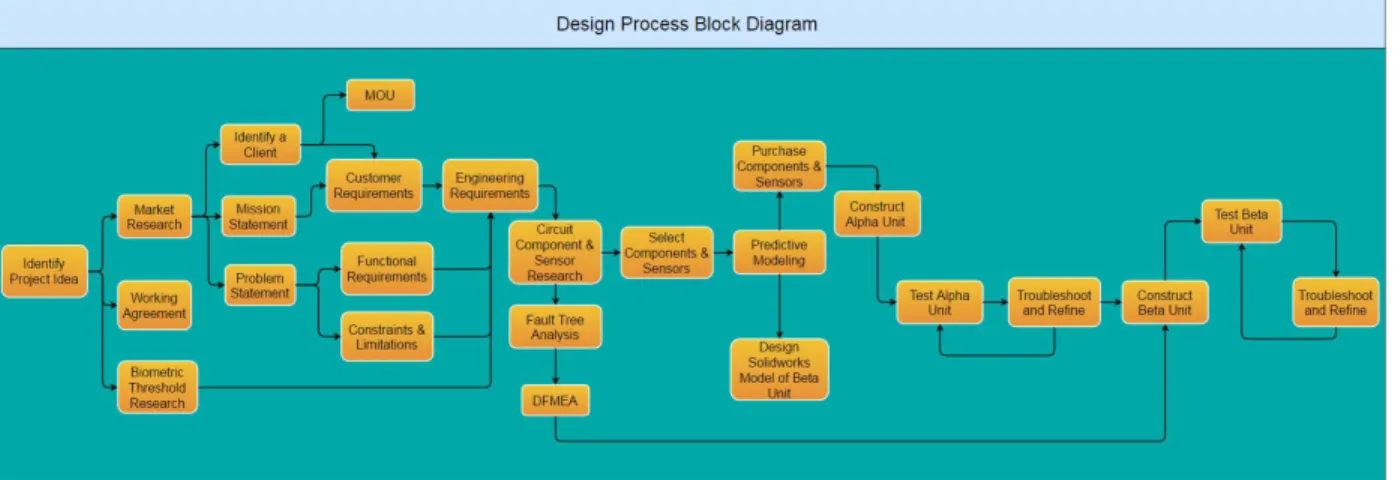
Our second goal was to work together as a team to follow a design process to develop a working prototype system. We outlined a general flowchart by which our design would take hold (Figure 3), as we developed our initial idea into a tangible, functional unit. We spoke to
representatives from two construction firms - Summit Construction Co. of Akron, OH, and Eichley Engineers Inc. of Concord, CA - to discuss our concept and gather information regarding customer preferences in the construction industry. We used this information to develop a set of Customer Requirements (Appendix A.1) and corresponding Engineering Requirements (Appendix A.2) to serve as our design independent product targets. Our objectives were driven by these requirements as well as the limitations (Appendix A.3) of available resources and various other constraints. We were allocated a budget of $500 for our project, which limited the quality of our components and
7 compelled us to think about and evaluate our purchase decisions carefully (Appendix E.1). In
addition, we only had a single academic year to form and develop an idea into a functional unit. We made significant progress toward our objectives throughout the academic year, as measured by our week-to-week goals and agendas we set for ourselves, and guided by our Gantt chart (Appendix D.1) and weekly group meetings. While we successfully completed our second goal of following the design process to develop an idea and transform it into a functional prototype, we did not make as much progress as we originally intended towards creating and testing a functional beta unit prototype.
Figure 3. Design Process Block Diagram
Methods/Procedures/Manufacturing
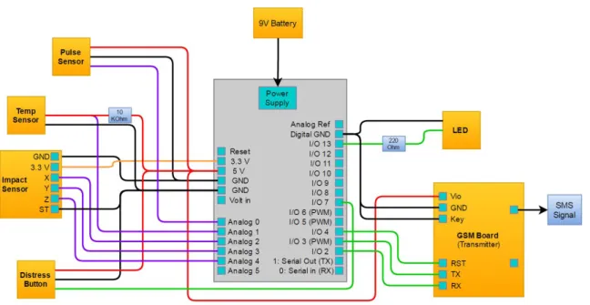
After extensive research and predictive modeling, we developed a design for our product and purchased the necessary components (Appendix A.4) based on our decision analysis matrices. These components were used to build a basic prototype model of our Smart Hard Hat, which measures a predetermined set of biometrics and alerts the wearer/supervisor if those biometric limits have exceeded safety thresholds. Part of our research included weighing the attributes of potential component selections against one another in the form of Pugh matrices, so that we could arrive at component choices that best fit the scope of our project (Appendix A.5). Our predictive modeling included 1) a SolidWorks model (Appendix B.1) to identify placement of components as well as ensure that they would fit properly within the hard hat and 2) circuit analysis to identify the electrical consumption and requirements of each component and the alpha circuit as a whole. Using this analysis, we develop a circuit schematic (Appendix B.2) which outlined how and where our sensors and other electrical components would be connected. Although this research and modeling was very beneficial, and would eventually save us time and money in the long run, it did set us behind on our original schedule because we underestimated the amount of modeling that our project required.
Upon the arrival of the components, we individually connected each sensor to the Arduino Uno board and developed the necessary code to operate the sensors. This process involved a significant amount of troubleshooting, as well as gathering more information on how the Arduino code is written and utilized. In writing the code, our goals were to see successful operation of the sensors and other components in tandem, a visual display of accurate measurements, and proper
8 alerts if a biometric threshold was exceeded. At the onset of the comprehensive master code
development, the thermistor, pulse sensor, accelerometer, and transmitter all had individual codes written as to allow the sensors to operate while attached to the Arduino board. After perfecting the individual codes, display readouts, and testing each of the components, we created a master code that used all of the sensors together simultaneously and provided an interface with the transmitter. We set thresholds in the master code to account for the biometric levels previously researched, so that if a limit is reached the transmitter is alerted. The transmitter would then send an alert to the supervisor via text message.
The advantage to first working with each component individually was that we had the opportunity to isolate problems and obstacles, as well as refine the code prior to compiling our master file. As we developed the overall code, we used the amount of memory available on the Arduino Uno board to store the sketches and operate the circuit as one of the coding constraints. After several versions of the code, we were able to lean the code so that it took up less than half of the onboard memory for the Arduino. In testing the code, we set the thresholds to lower levels than the biometric levels we researched so that we would not need to subject the initial circuit to extreme impacts or temperatures.
Performance Testing
As part of our alpha unit prototype, we developed a series of test protocols and conducted testing on each of the individual components to verify their functionality and ability to operate effectively and accurately within our device.
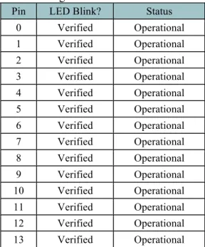
At the center of our design is our microcontroller, which ensures that all components are communicating properly and that all biometric signals are being evaluated. A testing protocol (Appendix C.1.1) was developed to test our Arduino Uno microcontroller. A sample code was uploaded to the board to test performance and each of the voltage pins were tested to ensure they were outputting accurate voltages. The final results for the microcontroller testing can be found in Appendix C.2.1.
Transmitting the signal is one of the most important differentiating factors for this project. The testing was based on the protocol, which can be found in Appendix C.1.2. The sample code that came with the breakout board was the initial code used for the testing. Using that code the FONA 800 GSM transmitter was tested by sending messages from Akron to 5 different locations, with distance varying from a few feet away all the way to California. The final results can be found in Appendix C.2.2. Since the transmitter is a go-no go feature, and all of the tests with the initial code, the transmitter passed its test protocol. Additionally, as each sensor was added into the final code, the transmission of the circuit was checked. Overall, throughout building the circuit the transmitter was tested 35 times. With each successful transmission the effectiveness of the transmitter was further proved.
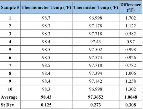
The performance of the Adafruit 10K Precision Epoxy Thermistor - 3950 NTC was tested in order to verify its accuracy in sensing temperature, as well as to compare its actual resistance to its theoretical resistance (Appendix C.1.3). First, the theoretical resistance values provided with the thermistor were compared to readings by both the Arduino code and those obtained through use of a multimeter (Commercial Electric Model: MS8332C). The results (Appendix C.2.3) showed that there
9 were no significant differences between the measured and theoretical resistance values. Next, the accuracy of the thermistor’s ability to measure temperature was assessed. The subject’s temperature was measured at the axilla, with the arm fully adducted to hold the thermistor in place, and at the temporal artery, using a finger to hold the sensor in place. Once the readings stabilized, the temperature was recorded and then compared to a reading taken in the same locations by a digital thermometer. These measurements were taken 15 times at the axilla, and 10 times at the temple. The results (Appendix C.2.3) demonstrated a statistically significant difference in the measurement of temperature between the thermistor and the digital thermometer. In order to compensate for this difference, we can adjust the threshold to reflect the discrepancy. Since completion of our alpha unit, we have verified the thermistor’s ability to communicate with the transmitter, but we still need to verify the signal has been sent as a result of our threshold values being exceeded. Once the thermistor has been incorporated into the hard hat assembly, it will also be important to verify the thermistor’s ability to accurately read body temperature while the subject is in motion. This will be measured by tracking the subject’s temperature while walking and at a light jog.
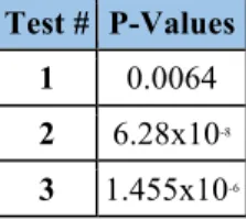
The Pulse Sensor Amped was tested in conjunction with a standard chest heart rate monitor (Polar FT1 Heart Rate Monitor) to determine the sensors accuracy at varying levels of physical intensity (Appendix C.1.4). The subject wore both monitors simultaneously and performed physical exercise at varying levels of intensity. The pulse sensor was worn around the subject’s left thumb and was covered with athletic tape to reduce the level of ambient light interference. Ten
measurements were taken at each level of physical intensity to ensure that statistically significant results could be obtained. The test results (Appendix C.2.4) were statistically evaluated using a two-sample t-test for each of the physical activity levels. Statistical analysis indicates that the means from the pulse sensor and the chest monitor are statistically equal for each of the activity levels (All P-Values > 0.05). We can conclude from our testing that, on average, the Pulse Sensor Amped (PPG sensor) records statistically equal values to that of a standard ECG chest heart rate
monitor. However, we did notice a high level of variance during the pulse sensor readings. The rapid fluctuation of heart rate on the pulse sensor could be a result from motion artifacts or
interference from ambient light. This observation was taken into account and the alpha unit code was adjusted to include a requirement for a sustained elevated heart rate for 30 seconds above threshold prior to an alert being sent.
The Sparkfun Triple Axis accelerometer (ADXL377) was tested using the motion-sensing rail equipment in place in the University of Akron’s Physics lab department. In order to test the accuracy of the accelerometer against an established system, we performed several tests (Appendix C.1.5) using an on-rails system, which can measure a variety of metrics related to motion (position, velocity, acceleration, etc.). We secured our Arduino board, along with the attached accelerometer, to a cart that moves uniaxially along the track set up for the motion sensor array. We then performed a series of ten tests in which we rolled the cart, stopped it using our hand, and measured the
acceleration values of both the motion sensor and the accelerometer. Our findings showed some statistical variance between the acceleration values recorded by the accelerometer and those shown in the motion-sensing system. Possible reasons for these differences include motion artifacts by a hand interfering with the sensor array, loose connections within the circuitry (as nothing up to this point has been soldered in place and may come loose with high impact), and variations related to the low acceleration values recorded. This is a recurring issue when testing the accelerometer; when looking
10 at concussion reports, most are recorded at much higher values than those tested in the lab. While our tests took the accelerometer up to 2-3g, a concussion scenario may cause upwards of 90g to the head. While our accelerometer is rated up to twice that, it becomes much harder to find a method of
accurately measuring acceleration and comparing it to the values given at forces that high. In a production scenario, our approach to ensuring the functionality and accuracy of the accelerometers put into our hard hats would most likely involve approving a supplier who can be validated as consistently providing quality components, negating the need to perform incoming inspections on these parts in-house. Additionally, we could pursue the option of contracting testing with an outside company to validate the accuracy and functionality of the accelerometer with respect to applied forces.
Lastly, the distress button will also need to be tested to verify that it communicates with the transmitter consistently and sends an alert in the event the user would require immediate assistance. We have thus far verified its ability to send a signal to the transmitter; we just need to document its repeatability.
Future Directions
Due to the limited amount of time available to complete this project, we were unable to reach the level of product functionality we originally planned. In the future, the pulse sensor would need additional coding to isolate sources of signal interference in order to reduce fluctuation in the
readings. This would allow for a more accurate and precise device to carefully measure the worker’s heart rate. Additionally, several issues with the accelerometer readings indicate that some
refinements would need to be made to accurately and consistently report concussive forces delivered to the hard hat. Like the pulse sensor, sources of error would need to be isolated in order to evaluate the underlying issues.
Presently, our development has moved past our Alpha unit towards the construction of the Beta unit. Unlike the tabletop build of the Alpha unit, the Beta unit requires each circuit element to fit within the enclosed space of a hard hat. Using our Solidworks model as a guide for sensor placement, we have designed a system to hold the components in place within the hard hat shell. This system must be able to securely hold onto the delicate components should the user experience an impact, drop the hat, etc. For this Beta system, we purchased a flexible,
semi-permanent prototype board, or “proto-board” that would allow us to secure all components by way of soldering while still having the ease and functionality of a breadboard design. This proto-board will take up less room than our current breadboard, allowing us to secure all components within the hard hat and maintain the clearance necessary for the suspension of the hard hat to perform as intended. Once the components are secured in place, we would move on to developing a testing procedure to evaluate the functionality of the beta unit in the field. This includes sensor function and
communication, battery life of the unit, security of components, and other metrics to be identified. Due to constraints and limitations in regards to cost and time, there are several aspects of our device that could be implemented were we to take it past the scope of this project. Below is a list of future considerations if we were to bring the product to market:
• Testing for a standard hard hat (OSHA and ASTM) • Weatherproofing
11
• More durable/secure moldings • GPS functionality
• Different models with different feature levels (basic, intermediate and advanced models) • Unique thresholds customized for each worker
• Two way communication for safety alerts to workers • Hard-hat-to-hard-hat communication
• Color coordinated LED alerts to match the biometric limit exceeded • Data storage
• Industrial-quality components (shifting away from plug-and-play and towards customized
components)
• Quality Function Deployment to gain an in-depth picture of customer complaints and needs
while prioritizing them for future product development
Many of the above would also require a market analysis to determine demand for these functionalities. By expanding the scope our analysis to receive more feedback from other companies we could determine what functionalities best suit the needs of a company’s employees. Furthermore, after exploring market data we could create our very own sensor package in order to best meet these needs and sell it to our suppliers.
Additionally, we would ideally want to further test our beta unit in the field to ensure that the components can communicate well with the user interface in a real world scenario. This would allow us to troubleshoot and refine our design once introduced to obstacles that we may not experience in our bench-top testing of the alpha unit. Some of these obstacles can include disruption of signal due to blockage, motion artifacts of the sensors, or dislodging of the components within the hard hat.
References
[1] General Electric. GE 2014 Annual Report, 2015. Web.
[2] "Injury and Illness Prevention Programs White Paper." OSHA.gov. Occupational Safety and Health Administration U.S. Department of Labor, 2012. Web. 11 Nov. 2015.
[3] Liberty Mutual Research Institute. (2016). 2016 Liberty Mutual Workplace Safety Index.
[4] Sengupta, Ishita, Marjorie L. Baldwin, and Virginia Reno. "Workers' Compensation: Benefits, Coverage, and Costs (2012)." National Academy of Social Insurance Issue 17 (August, 2014). Web. 4 Mar. 2016.
[5] "Global Personal Protective Equipment (PPE) Market By Product, By End-Use Expected to Reach USD 62.45 Billion by 2022." Grandview Research. Oct. 2015. Web. 4 Mar. 2016.
[6] "Global Personal Protective Equipment (PPE) Market 2022 - Industry Trends, Market Size, Segments, Growth Prospects Report By Radiant Insights, Inc." M2presswire (2015): Points of View Reference Center. Web. 4 Mar. 2016.
[7] Carter, Britanny. "Personal Protective Equipment Manufacturing." IBIS World: Where Knowledge Is Power. 1 May 2015. Web. 1 Sept. 2015.
[8] "Smart Hat - LifeBEAM." LifeBEAM. Web.
[9] Griggs, Brandon. "Smart Football Helmet May Help Detect Concussions - CNN.com." CNN. Cable News Network, 9 June 2014. Web. 2015.
[10] Zarda, Brett. "A Smart Football Helmet Monitors Players’ Health.”. A Smart Football Helmet Monitors Players’ Health. Popular Science, 9 June 2009. Web.
[11] Chanthadavong, Aimee. "Laing O'Rourke Monitors Workers' Safety with a Smart Hard hat." ZDNet. 18 Nov. 2015. Web. 7 Mar. 2016.
12 [12] "OSHA Technical Manual (OTM) Section III: Chapter 4." Occupational Safety & Health Administration. N.p.,
28 Apr. 2015. Web.
[13] "Cold Stress." ELCOSH : Electronic Library of Construction Occupational Safety and Health. Construction Safety Association of Ontario, 2000. Web. 15 Nov. 2015.
[14] "Slow Heartbeat." Heart Rhythm Society. Web. 12 Nov. 2015.
[15] Fass, Bryan. "Heart Rate During a Heart Attack." LIVESTRONG. 24 Mar. 2011. Web. 12 Nov. 2015. [16] Welch, Laura. "The Aging Worker in the U.S. Construction Industry -- Occupational Health & Safety."
Occupational Health and Safety. 10 Mar. 2010. Web. 1 Nov. 2015.
[17] "Target Heart Rates." American Heart Association. 2015. Web. 13 Nov. 2015.
[18] Bailey, Laura. "Football Helmet Sensors Help Researchers Demystify Concussion in Young Athletes." University of Michigan, 18 Apr. 2012. Web. 15 Nov. 2015.
Appendices
Appendix A: Design Documents
A.1 Customer Requirements A.2 Engineering Requirements A.3 Project Limitations
A.4 List of Materials A.5 Pugh Matrices
Appendix B: Modeling Documents
B.1 Solidworks Models B.2 Circuit Schematic
Appendix C: Testing Documentation
C.1 Testing Protocols
C.1.1 Arduino UNO Microcontroller Testing Protocol C.1.2 Transmitter Testing Protocol
C.1.3 Thermistor Testing Protocol C.1.4 Pulse Sensor Testing Protocol C.1.5 Accelerometer Testing Protocol C.1.6 Push Button Testing Protocol C.2 Test Results
C.2.1 Arduino Uno Test Results C.2.2 Transmitter Test Results C.2.3 Thermistor Test Results C.2.4 Pulse Sensor Test Results C.2.5 Accelerometer Test Results
Appendix D: Scheduling Documentation
D.1 Gantt Chart
Appendix E: Budget Documentation
13
Appendix A.1: Customer Requirements
Customer Requirements
The Smart Hard Hat
Members: Ben DeShon, Dominic Conte, Darcy Fyffe, Charlton Johns, and Connor Langenderfer
REVISION HISTORY
Version Number Implemented By Revision Date Reason
1.0 DF 10/22/15 Initial Draft
1.1 CL, CJ, DF 11/10/15 Additions
1.2 Team 11/15/15 Additions
1.3 DF, DC 2/17
Revised to reflect customer requirements and table
14
Introduction
In a wide variety of manual labor industries, workers are often unaware that they are approaching dangerous vital thresholds until they have already overexerted themselves. A need exists to be able to monitor the worker's biometric signals so as to prevent the effects of overexertion before potential injury can occur. The intention is to design and develop a protective helmet that will satisfy the health and safety needs of our clients and consumer base, as well as our own personal standards of excellence. We aim to develop and construct a functioning protective headgear product that keeps the safety of the end user at the forefront of the design. Our goal is to improve overall safety monitoring for indoor and outdoor workers by monitoring biometrics in order to reduce overexertion, survey cranial impacts, and ultimately decrease workplace injuries. This report contains the Product Design Specifications for the Smart Hard Hat biometric tracking PPE headgear device.
Industries in need of a biometric safety monitoring PPE device:
● Construction
● Indoor Manufacturing
● Oil and Gas
● Mining
● Lumber
● Athletics
● Military
Section 1: Customer Usage Requirements
1.1 Size: The headband shall be adjustable
1.2
Weight: Weight of the device shall be kept to a minimum in order to reduce unwanted strain on the wearer.
1.3 Comfort: Device will be able to be worn for an extended period without discomfort
1.4 Usability: Device will not require additional training prior to use
1.5 Usability: Device shall work out of box
1.6 Fit: Hard hat shall fit all users
1.7 Ergonomics: Device shall not limit head/neck movement of the user in any way
1.8 Placement: Internal circuitry components shall not interfere with outfitting the hard hat with accessories
Section 2: Regulatory Requirements
15 2.2
Testing: Device shall be tested to ensure that the worker remains safe in regards to electrical components
2.3 OSHA: Must meet all required OSHA standards
Section 3: Technical Requirements
3.1 Temperature Measurement: Device shall accurately measure body temperature of the worker
3.2 Pulse Measurement: Device shall accurately measure heart rate of the worker
3.3 Impact Measurement: Device shall accurately measure impact forces inflicted on the worker
3.4 Distress Alert: Device will be able to send an immediate alert to supervisor if help is needed
3.5 Exceeded Threshold Alert: Device will be able to send an immediate alert to the worker if biometric limits are exceeded
3.6 Exceeded Threshold Alert: Device will be able to send an immediate alert to the supervisor if biometric limits are exceeded
3.7 Signal Transmission: Device will be able to send signals over a range of distances, terrains, and obstacles (walls, basements, etc.).
3.8 Power source: Battery shall be rechargeable or replaceable
3.9 Power source: Must provide sufficient power supply to operate the entire device
Section 4: Performance Requirements
4.1 Duration: Device must function for the entire work period
4.2 Power: Device will contain an on/off power switch.
4.3 Alert: Device will alert supervisor if worker is in danger
4.4 Alert: Device will alert worker if they are in danger
4.5 Environment: Device shall operate in a variety of climates and environments (See Section 8)
4.6
Measurements: Device shall continuously monitor bodily biometrics regardless of worker activity
16 5.1 Cost: Cost will not exceed $300
5.2 Aesthetic: Device will look similar to a standard hard hat
5.3 Aesthetic: Device will be available in a variety of colors
Section 6: Manufacturing Requirements
6.1 Manufacturability: Device will be able to be ordered in bulk
6.2 Materials: Existing materials will be used for manufacture
6.3 Materials: Chosen materials must withstand environmental conditions
6.4 Materials: Materials shall be lightweight
6.5 Materials: Materials shall be resistant to wear
6.6 Materials: Materials shall be non-irritating to human skin
6.7
Materials: Materials must demonstrate required mechanical properties to safely perform function and adhere to standards
Section 7: Packaging and Transportation Requirements
7.1 Packaging: Product shall not be damaged in transport
7.2 Package Dimensions: Product and insulation shall fit within standard size shipping container
7.3 Instructions: Each package to include one set of instructions for use
7.4 Labeling: Keep package upright, label required
Section 8: Environmental Requirements
8.1 Normal Use: Components shall operate under standard environmental conditions.
8.2 Resistance to Adverse Weather: Components shall withstand environmental conditions such as rain, snow, high humidity, high wind, and extreme cold/heat.
17 by perspiration and high temperature.
8.4 Packaging: Packaging shall be resistant to extremes in temperature, humidity, and adverse weather conditions
18
Appendix A.2: Engineering Requirements
Engineering Requirements
The Smart Hard Hat
Members: Ben DeShon, Dominic Conte, Darcy Fyffe, Charlton Johns, and Connor Langenderfer
REVISION HISTORY
Version Number Implemented By Revision Date Reason
1.0 DF 10/22/15 Initial Draft
1.1 CL, CJ, DF 11/10/15 Additions
1.2 Team 11/15/15 Additions
1.3 BD, DF 3/22/16
Updated content to reflect engineering requirements as
related to customer specifications
19
1.
INTRODUCTION
1.1. Purpose of the Smart Hard Hat Engineering Requirements Document
In a wide variety of manual labor industries, workers are often unaware that they are approaching dangerous vital thresholds until they have already overexerted themselves. A need exists to be able to monitor the worker's biometric signals so as to prevent the effects of overexertion before potential injury can occur. The intention is to design and develop a protective helmet that will satisfy the health and safety needs of our clients and consumer base, as well as our own personal standards of excellence. We aim to develop and construct a functioning protective headgear product that keeps the safety of the end user at the forefront of the design. Our goal is to improve overall safety monitoring for indoor and outdoor workers by monitoring biometrics in order to reduce overexertion, survey cranial impacts, and ultimately decrease workplace injuries. This report contains the Product Design Specifications for the Smart Hard Hat biometric tracking PPE headgear device.
Industries in need of a biometric safety monitoring PPE device:
● Construction
● Indoor Manufacturing ● Oil and Gas
● Mining ● Lumber ● Athletics ● Military
This document outlines the engineering requirements necessary for developing a product that meets the customer requirements.
2.
Customer Usage Requirements
2.1. Size2.1.1. The size range of commercial helmet sizes, from at least 6 ½ to 8 inclusive, shall be accommodated by one or more headbands [1].
2.1.2. The surface of the headband, in contact with the wearer's head, shall not be less than one-inch nominal width [1].
2.2. Weight
2.2.1. The total weight of the device shall not exceed 15 oz. for Class A or C helmets, and 30 oz. for Class D helmets [1].
2.3. Comfort
2.3.1. Suspension shall consist of a design that is soft, pliable, and conforms to the contours of the wearer's head.
2.3.2. Device shall utilize a sweatband that is soft, moisture absorbent, and able to quickly wick and evaporate moisture.
2.4. Usability
2.4.1. IFU (Instructions for Use) shall be included with each device. 2.4.2. Components shall be calibrated prior to shipment.
2.4.3. No assembly shall be required by the end user.
2.5. Fit
2.5.1. Hard hat shall be one size fits all with adjustable interior.
20 2.6.1. The product shall be intuitive for the worker.
2.6.2. The product shall add no opportunity cost to a physical laborer.
2.6.3. The product shall add minimal information access costs for the supervisor. 2.6.4. The product shall be comfortable to wear for the user.
2.7. Placement
2.7.1. Internal components shall be placed within the shell of the hat, not in contact with suspension.
2.7.2. Internal components shall not utilize accessory slots.
3.
Regulatory Requirements
3.1. Testing3.1.1. Hard hat shall protect worker in adherence to ANSI Z89.1 standards. 3.1.2. Device shall comply with IEC 61508 for electronic functional safety.
3.2. OSHA
3.2.1. Device must meet OSHA standard 1910.135 for head protection. 3.2.2. Device must meet OSHA standard 1926.100 for head protection.
3.3. Intellectual Property
Existing patents (USPTO) that shall not be breached are included, but not limited to:
● 9,129,499: Wireless Device for Monitoring Protective Headgear [2]
● 8,860,570: Portable wireless personal head impact reporting system [3]
● 9,082,284: Real time safety systems [4]
● 8,884,756: Monitoring device for use with protective headgear [5]
● 6,798,392: Smart Helmet [6]
● 20070177651: Body temperature measuring device for helmet or head gear [7]
4.
Technical Requirements
4.1. Temperature Measurement4.1.1. Must accurately and continuously measure body temperature ± 0.2 °F. 4.1.2. Must be able to detect body temperature range of 90 °F – 110 °F. 4.1.3. Must be compatible with the 9-12V range of the microcontroller. 4.1.4. Must be able to communicate with logic board continuously.
4.2. Pulse Measurement
4.2.1. Must accurately and continuously measure workers heart rate. 4.2.2. Must be able to detect pulse range of 0 - 300 bpm.
4.2.3. Must be able to communicate with logic board continuously. 4.2.4. Must be compatible with the 9-12V range of the microcontroller.
4.2.5. Must be able to obtain accurate pulse reading from the body placement of sensor.
4.3. Impact Measurement
4.3.1. Must be able to detect and alert impact forces above a 90g threshold. 4.3.2. Must be able to communicate with logic board continuously.
4.3.3. Must be compatible with the 9-12V voltage range of the microcontroller. 4.3.4. Must not be activated by normal worker movement, dropping of the hat, etc.
4.4. Distress Alert
4.4.1. Distress button must be a passive system unless put into the circuit by the user. 4.4.2. When activated, the distress button must communicate directly with the
microcontroller.
4.4.3. Distress button must be “go/no-go” in order to ensure signal shall be sent. 4.4.4. Must be placed in such a manner to prevent accidental activation.
21
4.5. Exceeded Threshold Alert
4.5.1. Biometric values above set thresholds shall trigger a visual LED display to alert the worker.
4.5.2. Biometric values above set thresholds shall trigger an alert message sent via SMS to the site supervisor.
4.6. Signal Transmission
4.6.1. Microcontroller
4.6.1.1. Must be able to communicate with all components.
4.6.1.2. Must be able to identify body temperature threshold of 100.4 °F. 4.6.1.3. Must be able to identify heart rate threshold of 160 bpm [8][9]. 4.6.1.4. Must be able to identify an impact force threshold of 90g[10]. 4.6.1.5. Must communicate any data outside of threshold range with data
transmitter.
4.6.1.6. Must monitor and process data from sensors continuously. 4.6.1.7. Must initiate feedback alert to user if thresholds are exceeded. 4.6.2. Data Transmission
4.6.2.1. Data transmitter must have signal strength to cover an entire work site, industry recommendations dictate a minimum of 250 yards line of sight distance, however a farther range is preferable [11].
4.6.2.2. Data transmitter must have a GSM compatible antenna to properly transmit data.
4.7. Power Source
4.7.1. Power source shall supply no less than 9V and no more than 12V to the device. 4.7.2. Power source must last for the duration of the 8 hour work period.
4.7.3. Power source must be rechargeable or replaceable.
4.7.4. Power Source shall not give off levels of heat that provide discomfort or hazard to the worker.
5.
Performance Requirements
5.1. Duration5.1.1. Device shall function accurately for the duration of the 8 hour work day.
5.2. Power
5.2.1. Device shall contain an on/off switch.
5.3. Supervisor Alert
5.3.1. Device shall send a text message via SMS to a pre-identified number to alert the supervisor of the exceeded biometric limit.
5.3.2. The message shall display the individual ID Number and a predetermined alert phrase if the distress option of the Smart Hard Hat is activated.
5.3.3. The messaging service shall be compatible with all SMS-enabled phones. 5.3.4. Data transmitter requires access to SMS network in order to transmit data.
5.4. Worker Alert
5.4.1. Device shall send an immediate visual feedback alert to the worker to indicate an exceeded biometric limit.
5.5. Environment
5.5.1. Device shall function in all standard environmental conditions and a variety of adverse weather conditions. See ‘Environmental Requirements’ below for details.
5.6. Measurements
5.6.1. Circuitry components will be secure within the device.
22 5.6.3. Circuitry code will take into account ambient light and movement artifacts, as
well as observed variances between the sensor and standard measuring equipment.
6.
Sales Requirements
6.1. Cost6.1.1. Production costs shall not exceed $100 per unit
6.1.2. Final retail price for the device shall not exceed $250 per unit
6.2. Aesthetics
6.2.1. Device shall be manufactured so as to maintain the aesthetics of a regular hard hat. All electronic components shall be incorporated internally and not interfere with the normal operating function of the hard hat shell.
7.
Manufacturing Requirements
7.1. Manufacturability7.1.1. Device shall be manufactured through a facility that employs cGMP (Current Good Manufacturing Practices) and has a current Quality System in place.
7.2. Materials
7.2.1. Existing materials for manufacture shall be used.
7.2.2. Chosen materials must withstand necessary environmental conditions (see ‘Environment’).
7.2.3. Materials shall be lightweight within designated limitations (see ‘Weight’). 7.2.4. Materials shall be resistant to wear. (See ‘Service Life’).
7.2.5. Materials shall be non-irritating to human skin.
7.2.6. Materials must demonstrate required mechanical properties to safely perform functions (see ‘Performance’) and adhere to testing standards (see ‘Standards’).
7.3. Service Life
7.3.1. OSHA does not specify the service life of a hard hat, and there is no standard expiration time frame for hard hats. The life span of a hard hat may vary
depending on the conditions at each work site. General manufacturing guidelines suggest that the suspension be replaced after no more than 12 months and the entire hat be replaced after no more than five years. If wear or damage is observed on either portion of the hat, it shall be replaced immediately [9].
7.3.2. Electronic components shall be checked every 3 months for wear and every 6 months for verification that sensors are still calibrated and working to transmit data properly. After any traumatic event is triggered the components shall be re-evaluated and checked for normal functionality.
8.
Packaging and Transportation Requirements
8.1. Packaging8.1.1. Device shall be packaged in such a way as to ensure the integrity of all internal components in case of accidental drops or impacts.
8.2. Instructions
8.2.1. IFU (Instructions for Use) shall be included in each packaged device.
23 8.3.1. Labels shall contain any relevant safety information, as well as all relevant
manufacturing identification and Regulatory requirements (country of origin, lot/batch number, date of manufacture, etc.)
8.3.2. Labels will include a description of the product identity 8.3.3. Labels will include a declaration of the net quantity
8.3.4. Labels will include the company name and place of business
9.
Environmental Requirements
9.1. Normal Use9.1.1. The device shall perform and not be damaged within the temperature range of -20 °F – 150 °F (-28.9 °C - 65.5 °C).
9.2. Resistance to Adverse Weather
9.2.1. Components shall be able to withstand environmental conditions such as rain, snow, high humidity, high wind, and extreme cold/heat.
9.3. Corrosion Resistance
9.3.1. Components shall be able to withstand humidity on the interior of the hat caused by perspiration and high temperature.
9.4. Packaging
9.4.1. Device will be packaged in standard U.S. shipping containers.
9.4.2. Packaging will include materials that will aid in the preservation of product quality if faced with adverse weather, drops, or impacts.
9.5. Cleaning
9.5.1. The hard hat shell must be able to withstand cleaning with mild soap and water. 9.5.2. The hard hat is to be stored away from direct sunlight.
9.5.3. The end user shall not use paints, chemicals, adhesives, or any chemical solvent that may prematurely degrade the hard hat or its internal components.
9.5.4. Sensors shall be calibrated as recommended in the user manuals to ensure proper measurements and function.
9.5.5. The power source shall be inspected every 6 months to ensure the device functions as intended.
10.
References
[1] American National Standards Institute. ANSI Z89.1-2014: Safety Requirements for Industrial Head Protection. June 03, 2014.
[2] Howard, John W., and Richard Cutler. Wireless Device for Monitoring Protective Headgear. THL Holding Company, LLC, Round Rock, TX (US), assignee. Patent US 9,129,499 B2. 8 Sept. 2015. Print.
[3] Thomas, Biju, and Timothy Bauer. Portable Wireless Personal Head Impact Reporting System. SenseTech, LLC, assignee. Patent US 8860570 B2. 14 Oct. 2014. Print.
[4] Prieto, Robert. Real Time Safety Systems. Fluor Technologies Corporation, assignee. Patent US 9082284 B2. 14 July 2015. Print.
[5] Howard, John W., and Richard Cutler. Monitoring Device for Use with Protective Headgear. THL Holding Company, LL, assignee. Patent US 8884756 B2. 11 Nov. 2014. Print.
[6] Hartwell, Peter G., and James A. Brug. Smart Helmet. Hewlett-Packard Development Company, L.P., assignee. Patent US 6798392 B2. 28 Sept. 2004. Print.
[7] Daugherty, Edward, and Craig Daugherty. Body Temperature Measuring Device for Helmet or Head Gear. Daugherty Edward P, Craig Daugherty, assignee. Patent US 20070177651 A1. 2 Aug. 2007. Print.
24 [8] Welch, Laura. "The Aging Worker in the U.S. Construction Industry -- Occupational Health &
Safety." Occupational Health and Safety. 10 Mar. 2010. Web. 1 Nov. 2015. [9] "Target Heart Rates." American Heart Association. 2015. Web. 13 Nov. 2015.
[10] Bailey, Laura. "Football Helmet Sensors Help Researchers Demystify Concussion in Young Athletes." University of Michigan, 18 Apr. 2012. Web. 15 Nov. 2015.
[11] Saunders, Barbara. "Biosensors to Prevent Heat Stroke Unveiled as Petro-Safety Tools." NEWS Rigzone. 9 Jan. 2012. Web.
25
Appendix A.3: Project Limitations
The following constraints and limitations will impact the Smart Hard Hat design:
• The weight of the hat - can not introduce unwanted strain on workers • The cost cannot exceed $500
• The time required to create a functioning prototype is limited to the academic year and must be
completed by the end of April 2016
• Team has limited experience working with sensors and electrical circuits
• Hard hat must meet ANSI/ISEA Z89.1-2009 testing standards for hard hats (if brought to market) • Sensors, Transmitters, Receivers, and other components must be compatible
• Hard hat must have a communicative range that is useful for any work zone size • Hard hat must have a battery life that functions for the length of an entire work shift
• Resources are limited to the abilities of our team and the contributions of our client (Not just in
terms of money, but also experience, testing machines, PPE knowledge/data, etc.)
26
Appendix A.4: List of Materials
The following are a current list of materials used in the Smart Hard Hat design:
• Arduino Uno Rev 3 • Breadboard
• Flexible Protoboard • Jumper wires
• Resistors (10 kΩ, 220 Ω)
• Pulse Sensor Amped
• SparkFun ADXL377 Triple Axis Accelerometer Breakout • 10k Precision Epoxy Thermistor
• 1 x 16mm Illuminated Pushbutton - White Momentary • FONA 800 GSM Transmitter
• Slim Sticker-type GSM/Cellular Quad-band Antenna • Lithium Ion Polymer Battery - 3.7v 500mA
• USB cable - A/MicroB (3ft) • T-Mobile Sim Card
• 9V Battery • Bright LED bulb
27
A.5: Pugh Decision Matrices
Logic Board Selection:Arduino Uno Adafruit FLORA Criteria Weight Rating (-1,0,1) Weighted Score Rating (-1,0,1) Weighted Score
Cost 2 0 0 0 0 Memory Capacity 3 1 3 0 0 Ease of use 3 1 3 1 3 Durability 2 0 0 -1 -3 Online Resources 2 3 1 0 0 Size 2 0 0 1 2 Total Score 7 2 Rank 1 2
Scoring Details for Logic Board Selection:
Criteria Arduino Uno Adafruit FLORA
Cost ~$25, not a significant price point difference from FLORA $20 not a significant price point difference from Arduino Memory
Capacity Due to increased size, Arduino has more space for code Small size yields less space for a functional code Ease of use Plug-and-play for easy switching of sensor networks Requires soldering for connections to board
Durability Not they sturdiest, but no extra worry from misconnecting power supply Potential to fry circuit if power supply connected incorrectly Online
Resources
Many available on Arduino website as well as various
forums Less resources available across the web Size Not as small as the FLORA but small enough to fit within our project Main draw for this unit, easy to fit inside a hard hat
Transmitter Selection: 433MHz SX1278 Long Range RF Wireless Transceiver Module RFM92W 915Mhz 20dBm LoRa Transceiver FONA 800
Criteria Weight Rating (-1,0,1) Weighted Score (-1,0,1) Rating Weighted Score (-1,0,1) Rating Weighted Score
Accuracy 1 1 1 1 1 1 1
Durability 2 0 0 -1 -2 1 2
Cost 1 1 1 1 1 -1 -1
Size 4 -1 -4 0 0 0 0
Communication to logic board 5 0 0 0 0 0 0
Ease of programming 2 -1 -2 -1 -2 1 2
Distance 5 0 0 0 0 1 5
Reusability 3 1 3 0 0 0 0
Reliability 3 1 3 0 0 0 0
Set-up for receiving end 5 -1 -5 -1 -5 1 5
Total Score -3 -7 14
28
Scoring Details for Transmitter Selection:
Criteria 433MHz SX1278 Long Range RF Wireless Transceiver Module RFM92W 915Mhz 20dBm LoRa Transceiver FONA 800
Accuracy - - -
Durability - - -
Cost $8 $9 $40
Size - - -
Communication to logic board Arduino Arduino Arduino
Ease of programming Not much support Not much sample code Lots of sample code
Distance 13 miles 12 miles Global
Reusability - - -
Reliability - - -
Set-up for receiving end Requires additional software - Text message
Thermistor Selection: 10K Precision Epoxy Thermistor - 3950 NTC SKIN PROBE W/400 SERIES TEMP TSD202B Skin Temp Surface Probe
Thermistor
LilyPad Temperature Sensor
Criteria Weight Rating (-1,0,1) Weighted Score Rating (-1,0,1) Weighted Score (-1,0,1) Rating Weighted Score (-1,0,1) Rating Weighted Score
Accuracy 2 1 2 1 2 1 2 -1 -2
Continuous 2 0 0 0 0 0 0 0 0
Durability 2 0 0 0 0 0 0 1 2
Cost 3 1 3 -1 -3 -1 -3 1 3
Size 2 1 2 1 2 1 2 0 0
Communication to logic board 3 1 3 0 0 0 0 1 3
Ease of programming 3 1 3 0 0 0 0 1 3
Sensor placement (location) 1 1 1 1 1 0 0 1 1
Reusability 2 1 2 -1 -2 1 2 1 2
Plug-and-play 3 1 3 0 0 0 0 1 3
Availability of supply 2 0 0 -1 -2 0 0 0 0
Total Score 19 2 6 10
Rank 1 4 3 2
Scoring Details for Thermistor Selection:
Criteria Thermistor - 3950 NTC10K Precision Epoxy SKIN PROBE W/400 SERIES TEMP Surface Probe ThermistorTSD202B Skin Temp LilyPad Temperature Sensor
Accuracy - - - Low accuracy according to reviews
Continuous - - - -
Durability - - - -
Cost (w/o shipping and tax) $4.00 Approx. 40 $155.00 $4.95
Size - - - -
Communication to
microcontroller Made for Arduino - - Made for Arduino
Ease of programming Fully functional code available Can develop code Can develop code -
Sensor placement (location) Anywhere Forehead, axilla Anywhere on skin -
Reusability Yes No Yes Yes
29
Availability of supply 1 50 1 1
Pulse Sensor Selection:
Pulse Sensor Amped SPO2 e-Health Sensor ECG e-Health Sensor
Criteria Weight Rating (-1,0,1) Weighted Score Rating (-1,0,1) Weighted Score Rating (-1,0,1) Weighted Score
Accuracy 2 0 0 0 0 0 0 Continuous 2 0 0 0 0 0 0 Durability 2 0 0 0 0 -1 -2 Cost 3 1 3 -1 -3 -1 -3 Size 2 1 2 0 0 1 2 Communication to microcontroller 3 1 3 0 0 0 0 Ease of programming 3 1 3 0 0 0 0
Sensor placement (location) 1 1 1 -1 -1 0 0
Reusability 2 0 0 0 0 -1 -2
Plug-and-play 3 0 0 0 0 0 0
Availability of supply 2 0 0 0 0 0 0
Total Score 12 -4 -5
Rank 1 2 3
Scoring Details of Pulse Sensor Selection:
Criteria Pulse Sensor Amped SPO2 e-Health Sensor ECG e-Health Sensor AdInstruments Pulse Transducer
Accuracy - - - -
Continuous - - - -
Durability - - - -
Cost (w/o shipping and tax) $25 Approx. $40 Approx. $61 Unknown
Size - - - -
Communication to microcontroller
Made for Arduino
Made for e-health platform - shield required for Arduino
Made for e-health platform - shield required for Arduino
8-pin DIN connection. Cannot find adaptor for Arduino Ease of programming
Sample Arduino code
available
Can develop code Can develop code Unable to connect to Arduino, cannot develop code Sensor placement (location) Anywhere there are arteries Finger Location with good electrical readings Finger
Reusability Yes Yes No Yes
Plug-and-play Yes Yes Yes No
Availability of supply 1 1 1 1
Accelerometer Selection:
SparkFun ADXL377 ST 497-13903-1-ND Criteria Weight Rating (-1,0,1) Weighted Score Rating (-1,0,1) Weighted Score
Accuracy 4 0 0 1 4 Continuous 2 0 0 0 0 Durability 2 1 2 1 2 Cost 2 1 2 1 2 Size 4 0 0 1 4 Communication to microcontroller 4 1 4 -1 -4 Ease of programming 5 1 5 -1 -5 Distance 1 0 0 0 0
30
Reusability 2 0 0 0 0
Plug-and-play 4 1 4 -1 -4
Total Score 17 -1
Rank 1 2
Scoring Details of Accelerometer Selection:
Criteria SparkFun ADXL377 ST 497-13903-1-ND
Accuracy +/- 200g +/- 400g
Continuous Yes Yes
Durability Same Same
Cost (w/o shipping and tax) Same Same
Size Larger Smaller
Communication to microcontroller Made for Arduino Requires setup
Ease of programming Sample Arduino code available Sample code available
Sensor placement (location) Same Same
Reusability Yes Yes
Plug-and-play Yes No
Availability of supply (# per order) 1 1
Push Button Selection:
On-Off Power Button / Pushbutton Toggle Switch
16mm Illuminated Pushbutton - White Momentary
Criteria Weight Rating (-1,0,1) Weighted Score Rating (-1,0,1) Weighted Score
Cost 3 1 3 1 3
Size 2 1 2 1 2
Incorporation within a Hard Hat 3 0 0 1 3
Ease of programming 3 1 3 1 3
Additional Features 1 0 0 1 1
Plug-and-play 2 1 2 0 0
Availability of supply (# per order) 1 1 1 1 1
Total Score 11 13
Rank 2 1
Scoring Details of Push Button Selection:
Criteria On-Off Power Button / Pushbutton Toggle Switch 16mm Illuminated Pushbutton - White Momentary
Cost w/o shipping $1.95 $1.95
Size - -
Incorporation within a Hard Hat - Shape and Threading makes it much easier to incorporate into the final unit
Ease of programming Code is available Code is available
Additional Features - Built in LED to alert when depressed
Plug-and-play Can be directly plugged into a breadboard Requires Soldering, but leads can be added much more easily
31
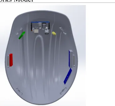
Appendix B.1: Solidworks Model
Figure 4. View from bottom, component placement inside the hard hat from left to right: Accelerometer (red), Pulse Sensor (green), Arduino Board, Thermistor (yellow), and Transmitter/Antenna (blue)
Figure 5. Cutaway view showing thermistor (yellow) and transmitter/antenna (blue) locations
32
Appendix B.2: Circuit Schematic
33
Appendix C.1.1: Arduino Uno Testing Protocol
Arduino Uno Board Test Protocol
Author:
Connor Langenderfer
Revision:
0.0
This is a test protocol to evaluate the accuracy of the Arduino Uno for use with the Smart
Hard Hat device.
Scope
This test protocol is intended to assess the Arduino Uno board’s accuracy and functionality within the Smart Hard Hat design project.
Objective
This testing protocol aims to ensure that the Arduino Uno board used in the Smart Hard Hat device functions in accordance with a predetermined code.
Equipment
• Arduino Uno Board
• Laptop with Arduino software
• Breadboard
• LED
• 200 ohm resistor
• Patch cables
• Arduino sample code (LED)
• Multimeter (Commercial Electric Model: MS8332C)
Procedure
1. A small sample circuit (Arduino LED tutorial) will be built using the Arduino Uno board and
breadboard.
2. A sample code (Arduino LED tutorial) will be downloaded to the Uno board and tested to see that
the board functions as intended (LEDs turn on).
3. Using a multimeter, measure and record the voltage output for the pin being used to ensure the
appropriate 5V or 3.3V as indicated on the board
4. Using a multimeter, measure and record the current coming from the pin being used
5. This can be repeated for all pins that may be used in the final Smart Hard Hat design to ensure
34
Appendix C.1.2: Transmitter Testing Protocol
Transmitter Test Protocol
Author:
Charlton Johns
Revision:
0.0
This is a test protocol to evaluate the accuracy and functionality of the FONA 800 GSM
Transmitter for use with the Smart Hard Hat device.
Scope
This test is intended to prove the essential functionality and data transmission range of the FONA 800 GSM Transmitter during use.
Objective
The objective of this test protocol is to determine the effectiveness of data transmissions from the FONA 800 GSM Transmitter over a range of distances, obstacles and signals.
Equipment
• FONA 800 Transmitter
• Antenna
• Fully charged battery
• Arduino UNO Microprocessor
• Breadboard
• Laptop with Arduino connecting cable
• Cell Phone
Procedure
1. Connect FONA 800 unit to the Arduino board.
2. Using the Laptop and an adequate code, create a signal message to send.
3. Select the number of whom should receive the message.
4. Send message through the transmitter.
5. Verify receipt of message on cell phone.
35
Appendix C.1.3: Thermistor Testing Protocol
Temperature Sensor Test Protocol
Author: Dominic Conte
Revision: 0.1.1
This is a test protocol to evaluate the accuracy of the temperature sensor during the
development of the Smart Hard Hat.
Scope
This test is intended to provide empirical evidence for the continued functionality and accuracy of the Adafruit 10K Precision Epoxy Thermistor - 3950 NTC, and its ability to work within the Smart Hard Hat system.
Objective
To verify the accuracy of the Adafruit 10K Precision Epoxy Thermistor and its ability to work with the Arduino.
Sample Size
Ten (10) measurements will be recorded in each testing setup in order to accurately determine the statistical significance of the data collected.
Equipment
• Adafruit 10K Precision Epoxy Thermistor
• Arduino Uno
• Breadboard
• FONA 800 Transmitter
• Multimeter (Commercial Electric Model: MS8332C)
• Digital Thermometer (Walgreens Flex Tip 2 Second Digital Thermometer, Item No: 354062)
Procedure
1. Verify Resistance
1. Connect the thermistor to the Arduino Uno
2. Place thermistor at temperature sensing location on the body, and allow the reading to stabilize according to the Arduino’s output. Record the temperature and measured resistance shown. 3. While maintaining the placement of the thermistor, disconnect it from the Arduino board and
measure its resistance using a multimeter. 4. Repeat 10 times
5. Compare the measured resistances to the theoretical resistance of thermistor. (Theoretical Values given here: https://www.adafruit.com/datasheets/103_3950_lookuptable.pdf)
2. Verify Temperature Readings
36 2. Place thermistor at temperature sensing location on the body, and allow the reading to stabilize
according to the Arduino’s output. Record the temperature, and note the time it takes for
![Figure 2. Projected Growth of Global PPE Market. Adapted from Grandview Research [5]](https://thumb-us.123doks.com/thumbv2/123dok_us/1108813.2647538/6.918.196.730.238.550/figure-projected-growth-global-market-adapted-grandview-research.webp)