6703/6704 ANALOG OUTPUT DEVICE CALIBRATION
P
ROCEDURE
Version 1.0
Introduction: This Document’s Scope
The following procedure for verifying and calibrating the National Instruments 6703/6704 analog output products contains three main sections:
• Calibration Overview. This introductory section tells you what calibration is, why you should calibrate, and how often you should do it. This section also explains internal and external calibration.
• Equipment and Other Test Requirements. This section describes what you need to do before you can calibrate your device, including an overview of the test equipment, software, calibration functions, and environment needed for calibration.
• Calibration Process. This section provides detailed step-by-step instructions for verifying and calibrating your device.
This document does not cover programming technique or compiler configuration because of the number of programming languages and styles that can be used to perform calibration. However, the National Instruments data acquisition driver, NI-DAQ, has many online help files that contain compiler-specific instructions and detailed function explanations. You can add these help files when NI-DAQ is installed on your calibration computer.
Calibration Overview
This section defines calibration, describes why it is necessary, and explains when you should do it. This section also covers internal and external calibration.
What Is Calibration?
Calibration is a procedure of reading offset and gain errors from a data acquisition (DAQ) board and updating special analog calibration circuitry that corrects these errors. National Instruments calibrates every 6703/6704 product at the factory. During the factory-calibration procedure, the calibration constants—values used to update the analog calibration circuitry—are stored in nonvolatile memory on the board. From memory, these values are loaded and used as needed.
Why Calibrate?
Offset and gain errors may drift with time and temperature. As a result, the factory-set calibration constants may become invalid, requiring calibration to achieve the specified accuracy of the board.
How Often Should You Calibrate?
The measurement requirements of your application indicate how often the 6703/6704 products need to be calibrated to maintain accuracy. National Instruments recommends that you perform a complete calibration at least once every year. This interval may be shortened to 90 days or six months depending on the demands of your application.
Calibration Options: External Versus Internal
6703/6704 products have two different calibration options, an internal or self-calibration, and an external calibration. Both of these calibration modes remove error from measurements.
Internal Calibration
All 6703/6704 devices perform continuous internal calibration using special calibration channels. These devices each have 16 voltage outputs and two voltage calibration channels. The 6704 also has 16 current outputs and two current calibration channels. All the output and calibration channels get scanned and refreshed together. The outputs of the calibration channels for the 6703 and 6704 are continuously compared to the onboard reference, and the 16-bit DAC’s offset and gain are adjusted to minimize the errors of the calibration channels. Since the 6703 and 6704 have excellent channel-to-channel matching of offset and gain errors,
minimizing the errors on the calibration channels also minimizes the errors for all of the voltage and current outputs.
External Calibration
External calibration uses a high-precision voltage and current device to measure errors on the board outputs. These errors are then corrected with a set of calibration constants that adjust the offset and gain of the 16-bit DAC. This ensures that the output voltages and currents fall within the board specifications.
Because of the 6703/6704 calibration circuitry, the only calibration adjustment you must make is to adjust the values of the calibration channels to account for time- or temperature-related drift of the onboard reference. The board is calibrated at the factory and the calibration constants are loaded into nonvolatile memory.
How Long Does Calibration Take?
Automated calibration procedures can reduce the calibration and verification process to approximately 10 minutes. However, manual calibration and verification can take as long as 1 hour. You can automate the adjustment and verification procedure if you have access to
programmable standards such as the Fluke 5700A or HP3458A, which can be controlled via a GPIB connection. You can then program the entire procedure to save time and effort.
Equipment and Other Test Requirements
This section describes the test equipment, software, calibration functions, and environment needed to calibrate your 6703/6704 board. Before calibrating your board, you must perform the following steps:
1. Install the NI-DAQ driver on the calibration computer. For specifics on NI-DAQ, refer to the Installing NI-DAQ section later in this document. 2. Properly configure the board to be calibrated. For configuring
instructions, refer to the Configuring Your Board in NI-DAQ section later in this document.
3. Write calibration software to communicate with the board via NI-DAQ function calls. For information on writing software, refer to the Writing Your Calibration Procedure section later in this document.
Installing NI-DAQ
Since 6703/6704 boards are PC-based measurement devices, you must have the proper board driver installed in the calibration system before attempting any calibration. For the 6703/6704 calibration procedure, you will need the latest version of the National Instruments NI-DAQ driver installed on the calibration system. This driver, which configures and controls the DAQ device, is available at www.natinst.com.
The driver supports a number of programming languages, including LabVIEW, LabWindows/CVI, Microsoft Visual C ++, Microsoft Visual Basic and Borland C ++. When you install the driver, you need only install support for the programming language that you intend to use.
For documentation that explains the use of the driver, install the following PDF files:
• NI-DAQ Function Reference Manual for PC Compatibles • NI-DAQ User Manual for PC Compatibles
These two manuals provide detailed information on using the NI-DAQ driver. The function reference manual includes information on the functions in the driver. The user manual provides instructions on installing and configuring National Instruments DAQ devices and detailed
information on creating applications that use the NI-DAQ driver. These manuals will be your primary references for writing your calibration utility. For further information on the products you will be calibrating, you may also want to install the device user manual.
You will also need a copy of the ni6704Cal.dll, ni6704Cal.lib, and ni6704Cal.h files. The .dll provides calibration functionality that does not reside in the standard NI-DAQ driver, including the ability to protect the calibration constants, update the calibration date, and write to the factory calibration area. The factory calibration area and the calibration date should only be modified by a metrology laboratory or another facility that maintains traceable standards. You can access the functions in this .dll through any 32-bit compiler. These files are available on the National Instruments Web site at www.natinst.com.
Configuring Your Board in NI-DAQ
NI-DAQ automatically detects all 6703/6704 devices. However, to communicate with the boards, they must be configured in NI-DAQ. The following steps briefly explain how to configure NI-DAQ. Refer to the board user manual for detailed installation instructions. You can install this manual when NI-DAQ is installed.
1. Turn off the power to the computer that will hold the board. 2. Install the board in an available slot.
3. When the computer powers up, launch the Measurement & Automation Explorer utility.
4. Configure the board device number.
5. Click the Test Resources button to ensure that the board is working properly.
Your device is now configured.
Note After a board is configured with the Measurement & Automation Explorer, the device is assigned a device number. This number is used in each of the function calls to identify which DAQ device is to be calibrated.
Writing Your Calibration Procedure
The calibration procedure in the Calibration Processsection later in this document provides step-by-step instructions on calling the appropriate calibration functions. These calibration functions are C function calls from the NI-DAQ driver that are also valid for Visual Basic programs. Although LabVIEW VIs are not discussed in this procedure, you can program in LabVIEW using the VIs that are named similarly to the NI-DAQ function calls in this procedure. Refer to the Flowchartssection for illustrations of the code used at each step of the calibration procedure.
Often you must follow a number of compiler-specific steps to create an application that uses the NI-DAQ driver. The NI-DAQ User Manual for PC Compatibles details the required steps for each of the supported compilers. Be aware that many of the functions listed in the calibration procedure use variables that are defined in the nidaqcns.h file. To use these variables, you must include the nidaqcns.h file in your code. If you do not want to use these variable definitions, you can examine the function call listings in the NI-DAQ documentation and the nidaqcns.h file to determine what input values are required.
Recommended Test Equipment
To perform calibration, you need a high-precision voltage and current measuring device. This device should be at least 10 ppm (0.001%) accurate. National Instruments recommends that you use the Hewlett-Packard 3458A DMM for calibration.
If you do not have the exact instrument, use the previously mentioned accuracy requirements to select a substitute calibration standard.
If you do not have custom connection hardware, you may need a connector block such as the National Instruments CB-68 and a cable such as the SH6868-D1. These components give you easy access to the individual pins on the 68-pin board I/O connector.
Environmental Issues
Be aware of these connection issues and environmental concerns:
• Keep connections to the DAQ device as short as possible. Long cables and wires can act as antennas by picking up extra noise that would affect calibration.
• Maintain the temperature between 18–28 °C. • Keep relative humidity below 80%.
• Use shielded copper wire for all cable connections to the device. It is often advisable to use twisted-pair wire to eliminate noise and thermal offsets.
• Allow a warm-up time of at least 15 minutes for PXI/PCI/AT bus devices and 30 minutes for PCMCIA cards to ensure that the measurement circuitry is at a stable operating temperature.
Calibration Process
To calibrate your device, follow these main steps:
1. Verify the existing operation of the board. This step, which is covered in the Verifying Your Board’s Operation section, allows you to confirm that the board was in specification prior to calibration. 2. Perform an external calibration that adjusts the board calibration
constants with respect to a known voltage source. This step is described in the Calibrating Your Board section.
3. Perform another verification to ensure the board is operating within its specifications after calibration.
Verifying Your Board’s Operation
Verification determines how well the board is meeting its specifications. By performing this procedure, you can see how your board has operated over time. This information can help determine the appropriate calibration interval for your application.
The verification procedure is divided into the major functions of the device. Throughout the verification process, use the tables in the Accuracy Specification section later in this document to see if your device needs to be calibrated.
Verifying Voltage Output
This procedure checks the operation of the board by verifying that the output of voltage channel zero is within specifications. Because of the channel-to-channel matching of the 6703/6704 voltage channels, if voltage channel zero is operating within specifications, all the voltage channels should be operating within specifications. However, if you want to verify the channels individually, this procedure can be easily expanded to verify all the voltage channels by performing the procedure once for each voltage channel. To do this, perform the procedure once for each value of the channel parameter from 0 to 15. Each time you repeat the procedure, you will also need to connect the appropriate channel to your DMM. See the
PCI/PXI-6703/6704 User Manual for the pin numbers corresponding to each channel. To verify the voltage output, make sure that you have read the Equipment and Other Test Requirements sections covered previously, and follow these steps:
1. Run the Get_Cal_Date function contained in ni6704Cal.dll to check the board’s previous calibration date.
2. Connect the DMM to the board as shown in the following table:
3. Place the DMM in voltage mode.
4. Run AO_VWrite with chan set to 0 and voltage set to 0.0. This will output 0.0 V on voltage channel 0.
5. Compare the resulting value shown by the DMM to the upper and lower limits listed in Specifications section later in this document. If the value falls between these limits, the test is considered to have passed.
Signal Name Description 6703/6704 Output DMM Input
VCH0 Voltage Channel 0 Pin 34 High
6. Run AO_VWrite with chan set to 0 and voltage set to 10.0. This will output 10.0 V on voltage channel 0.
7. Again, compare the resulting value shown by the DMM to the upper and lower limits listed in Specifications table later in this document. If the value falls between these limits, the board passes voltage
verification.
8. Disconnect the DMM from the board.
You have now verified the voltage output of your board.
Verifying Current Output (6704 Only)
This procedure checks board operation by verifying that the current output of channel 16 is within specifications. Because of the channel-to-channel matching of the 6704 current channels, if current channel 16 is operating within specifications, all the current channels should be operating within specifications. However, you may verify the channels individually by performing the procedure once for each current channel. To do this, perform the procedure once for each value of the channel parameter from 16 to 31. You will also need to connect the appropriate channel to your multimeter each time you repeat the procedure. See the
PCI/PXI-6703/6704 User Manual for the pin numbers corresponding to each channel.
To verify current output, make sure that you have read the Equipment and Other Test Requirements section previously covered, and follow these steps.
1. Run the Get_Cal_Date function contained in ni6704Cal.dll to check the board’s previous calibration date.
2. Connect the DMM to the board as shown in the following table.
3. Place the multimeter in current mode.
4. Run AO_VWrite with chan set to 16 and voltage set to 0.1. This will output 0.1 mA on current channel 16.
5. Compare the resulting value shown by the DMM to the upper and lower limits listed in Specifications section table. If the value falls between these limits, the test has been passed.
6. Run AO_VWrite with chan set to 16 and voltage set to 20.0. This will output 20.0 mA on current channel 16.
Signal Name Description 6704 Output DMM Input
ICH16 Current Channel 16 Pin 67 High
7. Again, compare the resulting value shown by the DMM to the upper and lower limits listed in Specifications section table. If the value falls between these limits, the board passes current verification.
8. Disconnect the DMM from the 6704.
You have now verified the current output of your board.
Calibrating Your Board
The 6703/6704 calibration procedure allows you to adjust the output calibration constants. At the end of each calibration procedure, these new constants will be stored in the user calibration area, ensuring that the board stores a permanent record of the calibration constants. Storing the calibration constants here also ensures that the constants automatically load when the board is powered up.
Calibrating Voltage Output
For the voltage outputs, you need to make offset and gain adjustments. You perform offset adjustment first, followed by gain adjustment. You will then perform both offset and gain adjustment again to ensure proper accuracy. This second set of offset and gain adjustments is necessary because a large initial change in one of the calibration channels can affect the accuracy of the other calibration channel. The following table lists the offset and gain channel numbers.
You need a DMM to measure the voltage outputs. Make sure that you have read the Equipment and Other Test Requirements section listed above, and follow these steps:
1. Run Set_DAQ_Device_Info with infoType set to
ND_CALIBRATION_ENABLE and infoValue set to ND_YES. This step configures the board so you can access the calibration channels. 2. Connect the DMM to the board as shown in the following table.
Calibration Channel 6703 Channel Numbers 6704 Channel Numbers Voltage Offset 16 32 Voltage Gain 17 34
Signal Name Description
6703/6704
Output DMM Input
VCH0 Voltage Channel 0 34 High
3. Place the DMM in voltage mode.
4. Run AO_VWrite with chan set to 0 and voltage set to 0.0. This will output 0.0 V on voltage channel 0.
5. Run AO_VWrite with the channel set to the voltage offset channel. Adjust the voltage parameter until the DMM reads as close to 0.0 V as possible. The value you write to the voltage offset channel will be close to 0.0 V. Increasing the voltage value will lower the magnitude of the voltage seen on voltage channel 0. Decreasing the voltage value will increase the magnitude of the voltage seen on voltage channel 0. 6. Run AO_VWrite with chan set to 0 and voltage set to 10.0. This will
output 10.0 V on voltage channel 0.
7. Run AO_VWrite with the channel set to the voltage gain channel. Adjust the voltage parameter until the DMM reads as close to 10.0 V as possible. The value you write to the voltage gain channel will be close to 10.0 V. Increasing the voltage value will lower the magnitude of the voltage on voltage channel 0. Decreasing the voltage value will increase the magnitude of the voltage on voltage channel 0.
You have now calibrated the voltage output.
Calibrating Current Output (6704 Only)
For the current outputs, you need to make offset and gain adjustments. You perform offset adjustment first, followed by gain adjustment. You will then perform both offset and gain adjustment again to ensure proper accuracy. This second set of offset and gain adjustments is necessary because a large initial change in one of the calibration channels can affect the accuracy of the other calibration channel. The following table lists the offset and gain channel numbers.
You will need a DMM to measure the current output. Make sure that you have read the Equipment and Other Test Requirements section covered previously, and follow these steps to adjust current output:
1. Run Set_DAQ_Device_Info with infoType set to
ND_CALIBRATION_ENABLE and infoValue set to ND_YES. This step configures the board so you can access the calibration channels. 2. Connect the DMM to the board as shown in the following table.
Calibration Channel 6704 Channel Numbers
Current Offset 33
3. Place the DMM in current mode.
4. Run AO_VWrite with chan set to 16 and voltage set to 0.1. This will cause the board to output 0.1 mA of current.
5. Run AO_VWrite with the channel set to the current offset channel. Adjust the voltage parameter until the DMM reads as close to 0.1 mA as possible. The value you write to the current offset channel will be close to 0.01 mA. Increasing the voltage value will lower the magnitude of the current on current channel 16. Decreasing the voltage value will increase the magnitude of the current on current channel 16. 6. Run AO_VWrite with chan set to 16 and voltage set to 20.0. This will
cause the board to output 20.0 mA of current.
7. Run AO_VWrite with the channel set to the current gain channel. Adjust the voltage parameter until the DMM reads as close to 20.0 mA as possible. The value you write to the current gain channel will be close to 19.608 mA. Increasing the voltage value will lower the magnitude of the current on current channel 16. Decreasing the voltage value will increase the magnitude of the current on current channel 16. You have now calibrated the current output.
Saving Calibration Values
Once you complete the calibration steps, you must store the new calibration constants in the user calibration area of the board EEPROM to ensure that your new calibration values are permanently saved and automatically loaded when the board is powered on. If the calibration is being performed by a metrology laboratory or another facility that maintains traceable standards, the calibration values should also be stored in the factory calibration area. This will protect the calibration constants by storing a copy of them in a location that cannot be overwritten by the user. To access the factory calibration area, you need the ni6704Cal.dll, available from National Instruments.
To save the calibration constants and update the calibration dates, follow these steps:
1. Run AO_Calibrate with operation set to 2 and calibrationArea set to 1. This stores the new calibration constants in the user calibration area of the board EEPROM.
Signal Name Description 6704 Output DMM Input
ICH16 Current Channel 16 Pin 67 High
2. Run Set_DAQ_Device_Info with infoType set to
ND_CALIBRATION_ENABLE and infoValue set to ND_NO. This configures the board so it is no longer possible to access the calibration channels.
3. If the calibration is being performed by a metrology laboratory or another facility that maintains traceable standards, call the Copy_Cal function in the ni6704Cal.dll. Calling this function copies the calibration values to the factory calibration area and updates the calibration date to match the system clock of the calibration computer. The board is now calibrated. You can verify the analog input and output operation by repeating the Verifying Your Board’s Operation section.
Specifications
The following tables are the specifications you should use when calibrating and verifying the 6703/6704. The tables show the specifications for 1-year and 24-hour calibration intervals.
Using the Tables
The following definitions describe how to use the specification tables in this section.
Test Point
The Test Point is the voltage value that is input or output for verification purposes.
24-Hour Ranges
The 24-Hour Range column contains the Upper Limits and Lower Limits
for the test point value. If the board has been calibrated in the last 24 hours, the test point value should fall between the upper and lower limit values. These limit values are expressed in volts or milliAmps.
1-Year Ranges
The 1-Year Range column contains the Upper Limits and Lower Limits for the test point value. If the board has been calibrated in the last year, the test point value should fall between the upper and lower limit values. These limits are expressed in volts milliAmps.
Table 1. Voltage Output Specifications
Test Point Value (V)
24-Hour Ranges 1-Year Ranges
Lower Limit (V) Upper Limit (V) Lower Limit (V) Upper Limit (V)
0.0 –0.0003125 0.0003125 –0.0003125 0.0003125
10.0 9.9992675 10.0007325 9.9990975 10.0009025
Table 2. Current Output Specifications (6704 Only)
Test Point Value (mA)
24-Hour Ranges 1-Year Ranges
Lower Limit (mA) Upper Limit (mA) Lower Limit (mA) Upper Limit (mA) 0.1 0.0996875 0.1003125 0.0996875 0.1003125 20 19.998515 20.001485 19.993795 20.006205
Flowcharts
These flowcharts show the appropriate NI-DAQ function calls for verifying and calibrating your 6703/6704 board. Refer to the Calibration Process section of this document, the NI-DAQ Function Reference Manual for PC Compatibles, and the NI-DAQ User Manual for PC Compatibles for additional information on the software structure.
Voltage Output Verification
Figure 1. Voltage Output Verification
Look at the 6703/6704 specification table to determine the appropriate ranges for the voltages and currents to be verified.
Get_Cal_Date (deviceNumber)
Connect the multimeter to channel voltage channel 0.
Verify that the voltage read by the multimeter is within range. AO_VWrite(deviceNumber,0,voltage)
Get_Cal_Date (deviceNumber)
Verify that the voltage read by the multimeter is within range. AO_VWrite(deviceNumber,0,voltage)
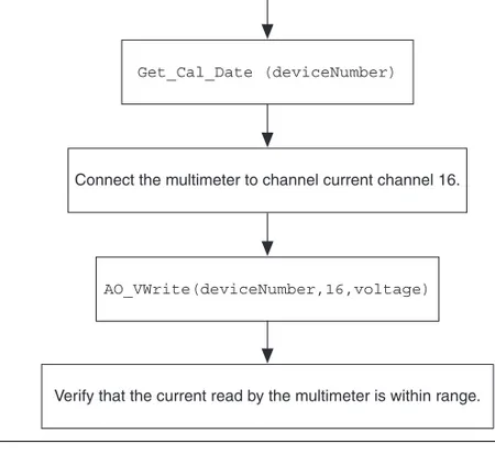
Current Output Verification (6704 Only)
Figure 2. Current Output Verification (6704 Only)
Look at the 6703/6704 specification table to determine the appropriate ranges for the voltages and currents to be verified.
Get_Cal_Date (deviceNumber)
Connect the multimeter to channel current channel 16.
Verify that the current read by the multimeter is within range. AO_VWrite(deviceNumber,16,voltage)
Voltage Output Calibration
Figure 3. Voltage Output Calibration
Connect the multimeter to channel voltage channel 0.
Set_DAQ_Device_Info(deviceNumber,ND_CALIBRATION_ENABLE,ND_YES)
AO_VWrite(deviceNumber,0,0.0)
AO_VWrite(deviceNumber,0,10.0)
6703: AO_VWrite(deviceNumber,16,voltage) Adjust voltage until the DMM reads 10.0 V. 6704: AO_VWrite(deviceNumber,32,voltage) Adjust voltage until the DMM reads 10.0 V.
6703: AO_VWrite(deviceNumber,17,voltage) Adjust voltage until the DMM reads 10.0 V. 6704: AO_VWrite(deviceNumber,34,voltage) Adjust voltage until the DMM reads 10.0 V.
Current Output Calibration
Figure 4. Current Output Calibration (6704 Only)
AO_VWrite(deviceNumber,16,0.1) Connect the multimeter to current channel 16.
AO_VWrite(deviceNumber,33,voltage) Adjust voltage until the DMM reads 0.1 mA.
AO_VWrite(deviceNumber,35,voltage) Adjust voltage until the DMM reads 20.0 mA. AO_VWrite(deviceNumber,16,20.0)
Saving Calibration Values
Figure 5. Saving Calibration Values
Set_DAQ_Device_Info(deviceNumber,ND_CALIBRATION_ENABLE,ND_NO) AO_Calibrate(deviceNumber,2,1)