Friction Analysis for Piston Ring of Seal Device in the Stirling Engine
Hou Shunqiang
1, a, Zhang Lili2,band Zhang Xiaoyan
3,c1
Qingdao Binhai University, Qingdao China
2Shandong University of Science and Technology, Qingdao China
3SAIC-GM-Wuling Automobile Co.Ltd SGMW , Liuzhou China
a hellospring111@163.com, b sdkd_lili@126.com, cxiaoyan1.zhang@sgmw.com.cn
Keywords: Stirling Piston ring; Dynamic seal; Friction and wear.
Abstract. The friction pair of piston ring-cylinder liner for the piston ring seal device of Stirling
Engine is plastic-metal friction pair, its working conditions for dry friction. So the wear resistance of the piston ring is poor, its service life is short. This paper regard integral non-backpressure piston rings group as the research object in order to reduce wear: First, establishes auto-free lubricating mechanical model to piston rings group; Then, set up the mathematical model, which to meet the requirements of the sealing performance, for friction analysis; At last, Experimental analysis in the Piston Ring Seal Device of Stirling Engine to prove that this model is correct and available.
Introduction
The opening with back pressure free lubricating piston rings is used in most piston ring seal device of Stirling Engine in domestic at present. During the working process of piston rings with opening back pressure free lubricating, the compressed medium pressure will press on the surface of piston ring’s inner column to make adhered pressure between piston ring and cylinder surface, which produce friction consumption in the process of piston rings’ reciprocating movement. However, as the piston ring of Stirling Piston works in the dry friction condition, it is easy to wear and its service life is short, besides, the sealing performance of Stirling Engine is affected by the friction character directly. This paper mainly bases on the operation condition of Stirling Engine to analyze the elements that affect the wear of piston ring and propose some measures to lengthen piston ring’s service life.
Improved Sealing Structure of Stirling Engine Piston Ring
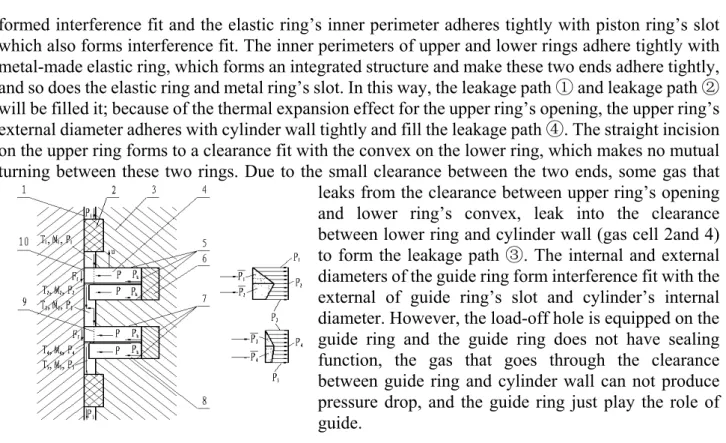
The improved sealing structure of Stirling Engine piston ring is as Fig. 1. Two piston rings and two guide rings are designed on the piston. The piston ring has a slot and double loop with an inside and outside structure. Two pieces are included in the outside ring and one is the upper ring the anther one is the lower ring. The upper one is the open type one with straight incision structure. The lower one is an integrated ring with a convex at the corresponded point with upper incision. Those two rings form the ring group and make two ends adhere. The inside ring is a spring lamination made by a stainless steel belt piece and it is 10~15mm longer than inside ring’s perimeter. Curve it into a lap round to be a elastic ring when install it and then embed it into piston ring to form interference fit. The guide ring has a slot and a ring with an uninstall hole, which can help guide ring without gas pressure and only play the role of oriented support. The piston ring and guide ring are produced by the Chinese Academy of Sciences Lanzhou Institute of Chemical Physics and the compound design is made by 40% Cu+ 60% F4 filled PTFE with self lubrication and good thermal conduction. With the force analysis as Fig.2 and ignoring the affection that produced by surface roughness (WA=0)between piston ring and cylinder wall, the upper ring end adhered tightly with the lower ring end with influence of gas pressure. Both of the two rings have incision and convex to make these rings into a set without mutual turning. The inner perimeter and metal elastic ring of upper and lower rings has
formed interference fit and the elastic ring’s inner perimeter adheres tightly with piston ring’s slot which also forms interference fit. The inner perimeters of upper and lower rings adhere tightly with metal-made elastic ring, which forms an integrated structure and make these two ends adhere tightly, and so does the elastic ring and metal ring’s slot. In this way, the leakage path and leakage path ① ①
will be filled it; because of the thermal expansion effect for the upper ring’s opening, the upper ring’s external diameter adheres with cylinder wall tightly and fill the leakage path . The straight incision ④
on the upper ring forms to a clearance fit with the convex on the lower ring, which makes no mutual turning between these two rings. Due to the small clearance between the two ends, some gas that leaks from the clearance between upper ring’s opening and lower ring’s convex, leak into the clearance between lower ring and cylinder wall (gas cell 2and 4) to form the leakage path . The internal and external ③
diameters of the guide ring form interference fit with the external of guide ring’s slot and cylinder’s internal diameter. However, the load-off hole is equipped on the guide ring and the guide ring does not have sealing function, the gas that goes through the clearance between guide ring and cylinder wall can not produce pressure drop, and the guide ring just play the role of guide.
1-cylinder liner 2- guide ring 3-piston 4-upper piston ring 5-leakage path 6① -elastic ring 7- leakage path 8① -lower piston ring 9- leakage path 10③ - leakage path④
Fig.1 the structure diagram of no-back-pressure piston ring set
Piston Rings’ Friction Analysis
The Elastic Specific Pressure Produces by Thermal Expansion.
The thermal expansion of piston can produce uniform pressure to the cylinder wall (Fig. 2)
Fig. 2 Loaded diagram of no-back-pressure nonmetal piston
See the metal ring as rigid body when calculate thermal deformation. On the basis of Hooke’s low during the working hours the tensile stress σ of nonmetal ring is [4]: σ = Eε =E(R−R0) R0 (1)
The loaded diagram of nonmetal ring during working hours is like drawing 4. It can be known from mechanical equilibrium relation that the resultant force of tensile stress σ on the y axis direction will equal to the component force that specific pressure P work on the inside of nonmetal ring on the y axis. That is to say: htσ =
π(
phdj β)
dβ = phdj0
2 sin
2 (2)
Put the formula (1)into (2)to get the formula between the elastic specific pressure of piston rings, P and the working temperature T1 :P=2Etα
(
T1−T0)
dj(i=1,2,3,4) (3)The high pressure sealing gas through the leakage path ③ (two places) and other seal surfaces, its pressure reduces from P1 to Pi (i=1,2,3,4) in sequence to corresponding gas cell; P−m is the average radial pressure that beard on the corresponding ring’s external diameter’s cylindrical surface and the pressure’s direction points from external to internal, besides, as the effect of thermal expansion during working hours, the elastic ring produces outward radial specific pressure P to the rings’ internal diameter. Meanwhile, as the compression when first assembling, the guide ring also produces outward radial specific pressure Pk to cylinder walls. The algebraic sum of these pressures in radial
direction is just the positive pressure that needed to form piston tings’ static friction.The radial elastic specific pressure of elastic rings Pk can be calculated from formula (4)[5] .
(
1)
08 . 7 − = e e e e k k t D D A E P (4)The average radial pressure that beard by each external diameter’s cylindrical surface will be seen
as formula (5)[6].
(
1)
2 1 + − + = m m m P P P (m=1,2,3,4) (5)The relation between average radial pressure and the sealed gas pressure P1 will be seen as formula (6)[6]. 1 4 1 3 1 2 1 1 0.76P,P 0.20P,P 0.076P,P 0.034P P− = − = − = − = (6) The radial specific pressure from gas to piston rings is like the following: 4 1
1 07 . 1 P P P m m m=
= = − (7)The Effect from Pistons’ Pace to Force of Sliding Friction.
Ff means the static friction when piston rings in the station of static and sealed, it can be calculated
from formula (8). ( ) ( ) 1 (1 1) 0 1 1.07 , 1 77 . 1 · · 8 P T F P t D D A E d T T t E F f e e e e k j f = − − + − =μ α (8)
The piston rings’ round surface and the cylinder walls form the relative sliding to produce sliding friction at sealed surface. We know that the size of sliding friction is related with the speed of relative movement of the things; therefore, the pace of pistons will affect the sliding friction (9)directly. When the system is sealed, the sliding friction can be expressed by the following function among working temperature T1, sealing medium pressure P1, piston pace v.
(
,)
υ2 2υ(
1, 1,υ)
1 1 1 P k k F T P T F Fd = f + − = d (9) Experimental AnalysesThe known physical quantity before experiment:
Chart 1 part of the certain experimental data
The mathematical computation model of friction and friction consumption power can be built according to the above formulas (1)-(9), and then find out the change regulation between the sliding friction Fd and other physical quantity. The measured dynamic friction in different operating
conditions have been drawn curve graphs as the following Fig.3, Fig.4 and Fig.5.
Conclusions
(1)It can be seen from Fig.3 that if the sealed gas pressure P1 and piston pace v are constant, the
force of sliding friction Fd will increase with the working temperature of piston rings and it will be
μ=0.12 E=280MPa t=1.6mm α=(10~15)×10-5 mm T0=25℃
dj=55mm Ek=193MPa Ae=0.2mm De=51.8mm te=1.75mm
steady at last. It is because when the working temperature increases the heat clearance of pistons’ opening will enlarge and the external diameter of piston will adhere tightly with cylinder wall. Just right now, the radial positive pressure from piston ring to the cylinder wall increase and the static friction Ff aggrandizes. When the heat clearance of opening enlarges to limit, the static friction will to
be maximum.
(2)It can be seen from Fig.4 that if the sealed gas pressures P1 and the working temperature T1 are
constant; when the pistons start to move its pace v is very low, however, with the increase of v the relative slip on the seal surface are severe and the radial wear quantity h=kpvt of piston ring will increase, and the frictional vibration will be severe and the sliding friction Fd will be increased as well.
When the radial wear quantity h of piston ring to be the maximum, the contact surface between piston ring’s external diameter and cylinder becomes very smooth and then the friction coefficient μ will decrease, the sliding friction Fd will decrease with decrease of static friction. Whenμ becomes
minimum; Ff will be steady as well as sliding friction Fd.
(3)It can be seen from Fig.5 that if the piston pace v and the working temperature T1 are constant,
the force of sliding friction Fd will decrease with the increasing of sealed gas pressure and then to be
steady. It is because when P1 increases the positive pressure N will decrease and this can be reflected
from formula (8). When the seal gas in cavity became thermal equilibrium state the seal gas pressure P1 will to be steady. The force of static friction Ff will decrease to a steady state value and the sliding
friction will be constant as well.
0 20 40 60 80 100 120 140 160 180 200 220 0.166 0.168 0.170 0.172 0.174 0.176 0.178 0.180 0.182 0.184 0.186 Fri ct io n /K N Temperature/.C 0.1 0.2 0.3 0.4 0.5 0.6 0.154 0.156 0.158 0.160 0.162 0.164 0.166 0.168 0.170 0.172 Frict ion/KN Velocity/(m/s)
Fig.3 curve between sliding friction Fd and sealed Fig.4 curve between sliding friction Fd and
working temperature T1 when P1=8MPa,ν=0.57m/s piston pace ν when T1=150 ,℃P1=2MPa
2 3 4 5 6 7 8 0.165 0.170 0.175 0.180 0.185 0.190 0.195 0.200 0.205 Fr ic ti on /K N Pressure/Mpa
Fig.5 curve between sliding friction Fd and sealed gas pressure P1 whenν=0.57m/s,T1=150℃
References
[1] Jin Donghan. Technology of Stiring Engine [M]. Harbin: Harbin Engineering University Press. 2009:162-166.
Engine [J].Lubrication and Sealing. 2006, (12):106-107
[3] Li Yanlin. Calculation & Practice of Free Lubrication Piston Rings’ Sealing Parameter and Minimum Opening Clearance [J]. Sinkiang Oil Science and Technology, 1992, (3):84-87.
[4] Zhu Yufeng. Design & Calculation of Working Clearance and Relative Interference Fit on No-back-pressure Piston Ring [N]. Hebei University of Science and Technology Journal, 2008-03-29(1):53-56.
[5] Peng Baocheng, Zhu Yufeng, etc. Affection Research of Elastic Rings to Piston Rings’ Sealing and Service Life [J]. Lubrication and Sealing, 2006, (180):97-98.
[6] Chen Geng, Jiao Guilong, Lu Dingji, etc. Tribology Design of Free Lubrication Compression Eengine Piston Ring [J].Shanghai Second Industrial University Journal, 1988,(1):1-8.