Release 1.0.0
Americas Headquarters
Cisco Systems, Inc. 170 West Tasman Drive San Jose, CA 95134-1706 USA http://www.cisco.com Tel: 408 526-4000 800 553-NETS (6387) Fax: 408 527-0883
CONTACT YOUR CISCO REPRESENTATIVE FOR A COPY.
The Cisco implementation of TCP header compression is an adaptation of a program developed by the University of California, Berkeley (UCB) as part of UCB's public domain version of the UNIX operating system. All rights reserved. Copyright©1981, Regents of the University of California.
NOTWITHSTANDING ANY OTHER WARRANTY HEREIN, ALL DOCUMENT FILES AND SOFTWARE OF THESE SUPPLIERS ARE PROVIDED“AS IS" WITH ALL FAULTS. CISCO AND THE ABOVE-NAMED SUPPLIERS DISCLAIM ALL WARRANTIES, EXPRESSED OR IMPLIED, INCLUDING, WITHOUT LIMITATION, THOSE OF
MERCHANTABILITY, FITNESS FOR A PARTICULAR PURPOSE AND NONINFRINGEMENT OR ARISING FROM A COURSE OF DEALING, USAGE, OR TRADE PRACTICE. IN NO EVENT SHALL CISCO OR ITS SUPPLIERS BE LIABLE FOR ANY INDIRECT, SPECIAL, CONSEQUENTIAL, OR INCIDENTAL DAMAGES, INCLUDING, WITHOUT LIMITATION, LOST PROFITS OR LOSS OR DAMAGE TO DATA ARISING OUT OF THE USE OR INABILITY TO USE THIS MANUAL, EVEN IF CISCO OR ITS SUPPLIERS HAVE BEEN ADVISED OF THE POSSIBILITY OF SUCH DAMAGES.
Cisco and the Cisco logo are trademarks or registered trademarks of Cisco and/or its affiliates in the U.S. and other countries. To view a list of Cisco trademarks, go to this URL:http:// www.cisco.com/go/trademarks. Third-party trademarks mentioned are the property of their respective owners. The use of the word partner does not imply a partnership relationship between Cisco and any other company. (1110R)
Any Internet Protocol (IP) addresses used in this document are not intended to be actual addresses. Any examples, command display output, and figures included in the document are shown for illustrative purposes only. Any use of actual IP addresses in illustrative content is unintentional and coincidental.
Preface... 4
Chapter 1: Welcome to Cisco UCS Performance Manager...6
Preparing Network Devices... 6
Preparing Storage Devices...7
Preparing Server Devices...8
Preparing Hypervisor Devices...8
Chapter 2: Installing with VMware vSphere... 10
Deploying a VMware virtual machine for Cisco UCS Performance Manager...10
Setting the root password...11
Chapter 3: Installing with Hyper-V Manager... 13
Creating a Hyper-V virtual machine for Cisco UCS Performance Manager...13
Installing Cisco UCS Performance Manager... 14
Chapter 4: Setting up Cisco UCS Performance Manager... 17
Accepting the License Agreement...17
Setting up Users... 18
Providing a license key...18
Adding UCS Domains... 19
Adding Infrastructure Devices... 20
Chapter 5: Maintaining Cisco UCS Performance Manager...24
Downloading Cisco UCS Performance Manager software... 24
Updating the Cisco UCS Performance Manager server operating system...24
Configuring network device settings... 25
Configuring DNS settings... 27
Appendix A: Configuring HTTPS communications... 29
Creating a self-signed SSL certificate... 29
Configuring the nginx server...30
Preface
Cisco UCS Performance Manager Installation Guide provides detailed instructions for installing Cisco UCS Performance Manager Express or Cisco UCS Performance Manager. Cisco UCS Performance Manager Express provides monitoring for Cisco UCS Domains, and Cisco UCS Performance Manager provides monitoring both Cisco UCS Domains and other infrastructure devices. For convenience, this document uses "Cisco UCS Performance Manager" generically. When needed, differences between the two products are noted explicitly.
Minimum system requirements
Cisco UCS domain size Cisco UCS Performance Manager virtual machine size
Category Monitored Servers Cores Memory Storage
Small 1-50 4 32GB 50GB
Medium 51-100 8 64GB 100GB
Large 101-500 12 96GB 150GB
Note Cisco UCS Performance Manager requires a storage subsystem that supports a minimum of 500 IOPS (input/output operations per second).
Supported client and browser combinations
Note All browsers must have Adobe® Flash® Player 11 installed, or a more recent version.
Client OS Supported Browsers
Internet Explorer 10 and above (compatibility mode is not supported) Firefox 30 and above
Windows 7 and 8.1
Chrome 30 and above Firefox 30 and above Chrome 30 and above Macintosh OS/X
Safari 7 and above Firefox 30 and above Linux/RHEL
Chrome 30 and above Related publications
Title Description
Cisco UCS Performance Manager Administration
Guide Provides an overview of Cisco UCS Performance Managerarchitecture and features, as well as procedures and examples to help use the system.
Cisco UCS Performance Manager Getting Started
Guide Provides specific instructions for using Cisco UCS PerformanceManager in the UCS environnment. Cisco UCS Performance Manager Installation Guide Provides detailed information and procedures for installing and
Title Description
Cisco UCS Performance Manager Release Notes Describes known issues, fixed issues, and late-breaking information not already provided in the published documentation set.
Documentation feedback
To provide technical feedback on this document, or to report an error or omission, please send your comments to ucs-docfeedback@cisco.com. We appreciate your feedback.
Welcome to Cisco UCS Performance
Manager
1
Cisco UCS Performance Manager provides visibility from a single console into UCS components for performance monitoring and capacity planning. It provides data center assurance of integrated infrastructures and ties application performance to physical and virtual infrastructure performance. This allows you to optimize resources and deliver better service levels to your customers.
Cisco UCS Performance Manager software is distributed as the following, self-contained packages: ■ A self-installing ISO package for Microsoft Hyper-V systems
■ A VMware OVA package for vSphere systems
The packages include both the run-time environment (CentOS 6.5) and the application software, and are ready to install on virtual machines. Once a package is installed, the Cisco UCS Performance Manager Setup Wizard guides you through the process of setting up UCS domains, defining users, and providing your license key. If your license is Cisco UCS Performance Manager, the Setup Wizard also includes a convenient way to add infrastructure devices. Cisco UCS Performance Manager uses standard management APIs to collect performance data, so no proprietary agents are installed on infrastructure devices. However, Cisco recommends that you review the following sections, and verify that the devices to monitor are ready to respond to requests for data.
Note If your license is Cisco UCS Performance Manager Express, skip the following sections.
Preparing Network Devices
Cisco UCS Performance Manager uses SNMP to provide customized or generalized support for many Cisco products.
The following table associates Cisco products with the customized Cisco UCS Performance Manager device types that support them. Device types are listed in the Network area of the Add Infrastructure wizard, which is both part of the setup wizard and available through the Cisco UCS Performance Manager web interface.
Cisco product Device type
Cisco Catalyst 6500 and 3560 Series Switches Cisco 6500 (SNMP) Cisco Nexus 5000 Series Switches Cisco Nexus 5000 (SNMP) Cisco Nexus 1000v Series Switches Cisco Nexus 1000V (SNMP) Cisco Nexus 3000 Series Switches Cisco Nexus 3000 (SNMP)
Cisco product Device type
Cisco Nexus 9000 Series Switches Cisco Nexus 9000 (SNMP) Cisco Catalyst 6500 Series Virtual Switching Systems Cisco VSS (SNMP) Cisco MDS 9000 Series Multilayer Switches Cisco MDS 9000 (SNMP) In addition, Cisco UCS Performance Manager provides two generalized device types.
Cisco product Device type
Cisco CatOS-based switches or routers Generic Switch/Router (SNMP) Cisco IOS-based switches or routers Cisco IOS (SNMP)
To prepare a switch or router device for monitoring, verify that an SNMP agent on the device is running.
Preparing Storage Devices
Legacy NetApp Filers
Cisco UCS Performance Manager uses SNMP to monitor legacy NetApp Filers that do not support the Data ONTAP® API (ZAPI).
Note The data gathered are approximate, because the values for many objects (Aggregate, Volume, Plex, and RAID group) are not exposed by the NetApp MIB.
To prepare a legacy NetApp Filer for monitoring, verify that SNMPv2 is installed, and then start an SNMP agent. Recent NetApp Filers
Cisco UCS Performance Manager uses HTTP to monitor NetApp Filers that support the Data ONTAP® API (ZAPI).
To prepare a recent NetApp Filers for monitoring, verify the following conditions: ■ The Filer is running in 7-Mode or C-Mode.
■ ZAPI is installed and enabled. Version 8.x, or a more recent version, is required.
Also, you need the username and password of an account on the Filer that is authorized to use ZAPI.
Note Many of the graphs for components types of EMC arrays display NaN when statistics logging is disabled on the EMC device. The logging feature has a low default timeout value, and must be set to a higher value or turned on again periodically.
EMC Storage Arrays
Cisco UCS Performance Manager uses the Web-Based Enterprise Management (WBEM) protocol to send queries to EMC Storage Management Initiative Specification (SMI-S) providers associated with EMC VMAX and VNX storage arrays.
To prepare EMC arrays for monitoring, verify that at least one EMC SMI-S provider is running for each type of array to monitor. (The VMAX and VNX data models are different.) In addition, you need the following information:
■ The username and password of a user account that is authorized to collect data on each SMI-S provider. ■ The IP address of each SMI-S provider.
■ The port number at which each SMI-S provider listens for requests.
Cisco recommends verifying that an SMI-S provider is responding to requests before adding it to Cisco UCS Performance Manager.
Verifying an SMI-S provider
To perform this procedure, you need a Linux host that has a network path to the SMI-S providers of the arrays to monitor.
Note Do not perform this procedure on the Cisco UCS Performance Manager host.
Perform this procedure to verify that the SMI-S providers associated with EMC arrays are configured correctly, and are responding to WBEM queries from command line tools.
1 Log in to a Linux host as root, or as a user with superuser privileges. 2 Install a WBEM command-line interface package, such as wbemcli.
3 Verify the SMI-S provider. Replace the variables with values that are valid in your environment.
wbemcli IP-Address:Port -u admin -p 'Password' -n root/emc --no-ssl ei('EMC_DiskDrive')
The expected result is a list of Disk Drive classes.
Preparing Server Devices
Linux Servers
Cisco UCS Performance Manager uses SNMP or SSH to monitor Linux servers.
To prepare a Linux server for SNMP monitoring, install an SNMP package on the server (for example, Net-SNMP) and start the agent.
To prepare a Linux server for SSH monitoring, install an SSH server package (for example, OpenSSH) and start the SSH daemon. Also, obtain the username and password of a user account on the server that has standard user privileges (root privileges are not required).
Windows Servers
Cisco UCS Performance Manager uses SNMP or WinRM to monitor the following Microsoft Windows systems: ■ Microsoft Windows Server 2012 and 2012 R2
■ Microsoft Windows Server 2008 R2
To prepare a Windows system for SNMP monitoring, start the SNMP service.
To prepare a Windows system for WinRM monitoring, refer to Appendix B, Preparing Windows Systems.
Preparing Hypervisor Devices
VMware vSphere servers
To prepare a VMware vSphere server for monitoring, verify the software version, and obtain the username and password of an account on the server that is authorized to use the vSphere API.
Microsoft Hyper-V servers
Cisco UCS Performance Manager uses WinRM to monitor the following Microsoft Hyper-V systems: ■ Microsoft Hyper-V Server 2012 and 2012 R2
■ Microsoft Hyper-V Server 2008 and 2008 R2
Installing with VMware vSphere
2
This procedure installs the Cisco UCS Performance Manager OVA package on a virtual machine managed by vSphere Server version 5.0.0, using VMware vSphere Client 5.0.0. The procedure is slightly different with different versions of VMware vSphere Client.
Note VMware vSphere Client 5.0.0 does not include a library that is needed to deploy compressed OVA files. You may uncompress the OVA package and then deploy it, or download and install the missing library. Cisco recommends installing the library.
From start to finish, installing Cisco UCS Performance Manager with VMware vSphere takes approximately 10 minutes or less.
Use the minimum system requirement information in the following table to create a new virtual machine for Cisco UCS Performance Manager.
Cisco UCS domain size Cisco UCS Performance Manager virtual machine size
Category Monitored Servers Cores Memory Storage
Small 1-50 4 32GB 50GB
Medium 51-100 8 64GB 100GB
Large 101-500 12 96GB 150GB
Deploying a VMware virtual machine for Cisco UCS Performance
Manager
1 Download the Cisco UCS Performance Manager package for VMware vSphere servers to your workstation. For more information, see Downloading Cisco UCS Performance Manager software on page 24.
2 Use the VMware vSphere Client to log in to vCenter as root, or as a user with superuser privileges, and then display the Home view.
Figure 1: vSphere client Home view
3 From the File menu, select Deploy OVF Template....
4 In the Source panel, specify the path of the Cisco UCS Performance Manager package, and then click Next >. 5 In the OVF Template Details panel, click Next >.
6 In the Name and Location panel, provide a name and a location for the server. a In the Name field, enter a new name or use the default.
b In the Inventory Location area, select a data center for the virtual machine. c Click Next >.
7 In the Host / Cluster panel, select a host system, and then click Next >.
8 In the Storage panel, select a storage system with sufficient space for your UCS system, and then click Next >. 9 In the Disk Format panel, select select Thin Provison, and then click Next >.
10 In the Ready to Complete panel, review the deployment settings, and then click Finish.
You may check the check box labeled Power on after deployment, or wait until the deployment is complete and then power on the virtual machine.
11 In the Home > Inventory > Hosts and Clusters panel, click the Summary tab, and then make a note of the IP address of the newly-deployed host.
Note If DHCP is not available in your environment, or if you want to change networking settings, see
Configuring network device settings on page 25.
Setting the root password
Perform this task immediately after deploying and starting a VMware virtual machine for Cisco UCS Performance Manager.
1 Use the VMware vSphere Client to log in to vCenter as root, or as a user with superuser privileges, and then display the Home view.
2 In the Home > Inventory > Hosts and Clusters panel, click the Console tab of the newly-deployed host. 3 In the console window of the host, log in as the root user, with password zenoss.
Figure 2: Example login prompt
4 The system prompts you to replace the default password with a new password. Figure 3: Change password prompt
a Enter the default password, zenoss. b Enter a new password, twice.
The Cisco UCS Performance Manager Administration menu displays.
c Use the down-arrow key to select Exit, then press Enter. Proceed to Setting up Cisco UCS Performance Manager on page 17.
Installing with Hyper-V Manager
3
This install procedure requires Microsoft Remote Desktop Client.
From start to finish, installing Cisco UCS Performance Manager with Hyper-V Manager takes approximately 30 minutes.
Use the minimum system requirement information in the following table to create a new virtual machine for Cisco UCS Performance Manager.
Cisco UCS domain size Cisco UCS Performance Manager virtual machine size
Category Monitored Servers Cores Memory Storage
Small 1-50 4 32GB 50GB
Medium 51-100 8 64GB 100GB
Large 101-500 12 96GB 150GB
Creating a Hyper-V virtual machine for Cisco UCS Performance Manager
1 Use Remote Desktop Connection to log in to a Hyper-V server as Administrator, or as a user withAdministrator privileges.
2 Download the Cisco UCS Performance Manager package for Hyper-V servers.
For more information, see Downloading Cisco UCS Performance Manager software on page 24. 3 Start Hyper-V Manager.
4 From the Action menu, select New > Virtual Machine....
5 In the New Virtual Machine Wizard dialog, display the Specify Name and Location panel. If the first panel displayed is the Before You Begin panel, click Next >.
6 In the Specify Name and Location panel, provide a name for the virtual machine, and then click Next >. 7 In the Specify Generation panel, select Generation 1, and then click Next >.
8 In the Assign Memory panel, enter the memory size for the virtual machine in the Startup memory field, and then click Next >.
For more information about memory size, refer to Installing with Hyper-V Manager on page 13.
9 In the Configure Networking panel, select Cisco VIC Ethernet Interface - Virtual Switch, and then click Next >.
10 In the Connect Virtual Hard Disk panel, select Create a virtual hard disk, enter the disk size for the virtual machine, and then click Next >.
For more information about disk size, refer to Installing with Hyper-V Manager on page 13. 11 In the Installation Options panel, specify the Cisco UCS Performance Manager ISO package.
a Select Install an operating system from a bootable CD/DVD-ROM.
b Select Image file (.iso), and then specify the location of the Cisco UCS Performance Manager ISO image file.
c Click Next >.
12 In the Summary panel, review the virtual machine specification, and then click Finish.
Hyper-V Manager creates the new virtual machine, and then closes the New Virtual Machine Wizard dialog. 13 In the Virtual Machines area of Hyper-V Manager, select the new virtual machine, and then right-click to select
Settings....
14 In the Hardware area of the Settings dialog, select Processor. Figure 4: Example: Starting a new virtual machine
15 In the Processor area, set the value in the Number of virtual processors field to the number of cores recommended for your installation.
For more information about the number of cores, refer to Installing with Hyper-V Manager on page 13. 16 Click OK.
Proceed to Installing Cisco UCS Performance Manager on page 14.
Installing Cisco UCS Performance Manager
Perform this procedure after creating a virtual machine for Cisco UCS Performance Manager in Hyper-V Manager. 1 In the Virtual Machines area of Hyper-V Manager, select the new virtual machine, and then right-click to select
Figure 5: Example: Starting a new virtual machine
2 In the Virtual Machines area of Hyper-V Manager, select the new virtual machine, and then right-click to select Connect.
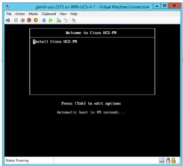
3 In the Virtual Machine Connection window, press ENTER or allow the automatic boot time to expire. Figure 6: Installation start screen
Figure 7: Root Password screen
5 Press the TAB key, and then press ENTER. The installation runs to completion after this input.
6 Write down the URL of the Cisco UCS Performance Manager interface.
Note If DHCP is not available in your environment, or if you want to change networking settings, see
Configuring network device settings on page 25.
Setting up Cisco UCS Performance
Manager
4
This section describes how to use the Cisco UCS Performance Manager Setup Wizard to set up UCS domains, define users, and provide your license key.
The Setup Wizard runs the first time you log in to the Cisco UCS Performance Manager web interface. (For more information about supported browsers and client operating systems, see Preface on page 4.)
The Cisco UCS Performance Manager web server listens at port 8080. So, if the IP address of your Cisco UCS Performance Manager virtual machine my-vm.example.com is 10.92.10.10, both of the following URLs return the login page.
■ http://my-vm.example.com:8080/ ■ http://10.92.10.10:8080/
Note The Setup Wizard times out after 20 minutes if you have not completed it. To start it again, close its browser window or tab, and then log in again.
To complete the Setup Wizard, you need the following items:
■ Authorization to accept the Cisco UCS Performance Manager end-user license agreement on behalf of your organization.
■ A password for the default administrative acount (admin).
■ A username and password for one additional administrative account.
■ The license key for your product (Cisco UCS Performance Manager Express or Cisco UCS Performance Manager). To obtain a license key, contact your Cisco representative.
■ The hostnames or IP addresses of UCS Domain servers in your environment. In addition, you need the
username and password of an account on each server that is authorized for read access to the resources you plan to monitor.
If your license is Cisco UCS Performance Manager, the Setup Wizard includes the Add Infrastructure page as the final step. The step is optional, and the page is a standard part of the Cisco UCS Performance Manager interface, so you can use it at any time. To use the Add Infrastructure page successfully as part of the Setup Wizard, review the device information in Welcome to Cisco UCS Performance Manager on page 6.
Accepting the License Agreement
Perform this procedure after installing Cisco UCS Performance Manager on a virtual machine and powering it on. 1 In a web browser, navigate to the login page of the Cisco UCS Performance Manager interface.
Cisco UCS Performance Manager redirects the first login attempt to the Setup page, which includes the End User License Agreement (EULA) dialog.
2 Read through the agreement.
3 At the bottom of the EULA dialog, check the check box on the left side, and then click Accept License button on the right side.
Figure 8: Bottom of EULA dialog
Setting up Users
Perform this procedure after accepting the EULA.
1 On the Cisco UCS Performance Manager Setup page, click Get Started!.
2 On the Setup Users page, enter a password for the admin user, and create an account for one additional user.
a In the Set admin password area, enter and confirm a password for the admin user account. b In the Create your account area, create one additional administrative user account.
c Click Next.
Providing a license key
To perform this procedure, you need a license key for Cisco UCS Performance Manager Express or Cisco UCS Performance Manager.
This is Step 2 of the Setup Wizard.
2 Proceed to the next task or repeat the preceding step.
■ If the product name matches the product you purchased, click Next.
■ If the product name does not match the product you purchased, repeat the preceding step.
Note The Cisco UCS Performance Manager interface includes an option for changing your license key.
Adding UCS Domains
This is Step 3 of the Setup Wizard.
1 On the Add UCS Domains page, provide connection credentials for one or more domains.
a In the Hostname or IP Address field, enter the fully-qualified domain name or IP address of a UCS domain server.
b In the Username field, enter the name of a user account in the UCS domain that is authorized for read access to the resources you plan to monitor.
c In the Password field, enter the password of the user account specified in the preceding step. d Click Add.
2 Review the information in the Connection Valid? column of the Domains table, and then remove a domain, add a domain, or continue.
■ If the final message in the Connection Valid? column is Authentication failed, click the button in the Remove column, and then try again to add a domain.
■ If the final message in the Connection Valid? column is Success, you may add another domain or continue to the next page.
3 Continue to the next page.
■ If your license is Cisco UCS Performance Manager Express, click Finish to continue to the DASHBOARD page of the web interface.
■ If your license is Cisco UCS Performance Manager, click Next to continue to the Add Infrastructure page.
Adding Infrastructure Devices
Note This step is not available in Cisco UCS Performance Manager Express. This is Step 4 of the Setup Wizard.
■ This step is optional. Click Finish to exit the Setup Wizard.
■ The Setup Wizard times out after 20 minutes if you have not completed it. You may restart Setup Wizard by closing its browser window or tab, and then logging in again. Also, you may add devices through the Add Infrastructure page at any time.
Adding Network Devices
This procedure is one of the options in step 4 of the Setup Wizard. For more information about network devices, see Preparing Network Devices on page 6.
1 In the Category area, select Network.
The protocol used to gather data from the device is included in the list, in parentheses. SNMP is the only protocol available for network devices.
3 In the Connection Information area, specify the devices to add.
a In the Enter multiple similar devices, separated by a comma, using either hostname or IP Addresses field, enter the hostname or IP address of one or more switch or router devices on your network.
b Optional: In the SNMP Community String field, change the default (public) if necessary.
This field is not used if the selected device supports both SNMP and NETCONF, and you provide a user name and password.
c Optional: In the Username field, enter the name of a user account on the device.
This field is only present when the selected device supports both SNMP and NETCONF. By providing a user name and password, you select NETCONF protocol.
d Optional: In the Password field, enter the password of the user account specified in the previous field. This field is only present when the selected device supports both SNMP and NETCONF. By providing a user name and password, you select NETCONF protocol.
e Click Add.
If you are finished adding devices, click Finish.
Adding Storage Devices
This procedure is one of the options in step 4 of the Setup Wizard. For more information about storage devices, see
Preparing Storage Devices on page 7. 1 In the Category area, select Storage.
2 In the Type list, select the product model of the storage device to add.
The protocol used to gather data from the device is included in the list, in parentheses. 3 In the Connection Information area, specify the devices to add.
a In the Enter multiple similar devices, separated by a comma, using either hostname or IP Addresses field, enter the hostname or IP address of one or more storage devices on your network.
b Optional: In the Username field, enter the name of a user account on the device. This field is not present when the device protocol is SNMP.
c Optional: In the Password field, enter the password of the user account specified in the previous field. This field is not present when the device protocol is SNMP.
d Optional: In the Port field, enter the port at which the device listens for data collection requests. This field is present only when the device protocol is SMIS Proxy.
e Check the Use SSL? check box to use secure communications to collect data, or uncheck the check box to use insecure communications.
This field is not present when the device protocol is SNMP. f Click Add.
If you are finished adding devices, click Finish.
Adding Server Devices
This procedure is one of the options in step 4 of the Setup Wizard. For more information about server devices, see
Preparing Server Devices on page 8. 1 In the Category area, select Servers.
2 In the Type list, select the operating system and monitoring protocol of the server to add. The protocol used to gather data from the device is included in the list, in parentheses. 3 In the Connection Information area, specify the servers to add.
a In the Enter multiple similar devices, separated by a comma, using either hostname or IP Addresses field, enter the hostname or IP address of one or more server devices on your network.
b Optional: In the SNMP Community String field, change the default (public) if necessary. This field is not present when the device protocol is SNMP.
c Optional: In the Username field, enter the name of a user account on the device. This field is not present when the device protocol is SNMP.
d Optional: In the Password field, enter the password of the user account specified in the previous field. This field is not present when the device protocol is SNMP.
e Optional: In the AD Domain Controller field, enter the IP address or hostname of the Active Directory Domain Controller on your network.
This field is only present when the device protocol is WinRM. f Click Add.
If you are finished adding devices, click Finish.
Adding Hypervisor Devices
This procedure is one of the options in step 4 of the Setup Wizard. For more information about hypervisor devices, see Preparing Hypervisor Devices on page 8.
2 In the Type list, select the hypervisor service to add.
3 In the Connection Information area, specify the service to add. a In the Device Name field, enter the name of the hypervisor service.
b In the Hostname / IP Address field, enter the hostname or IP address of the hypervisor service. c In the Username field, enter the name of a user account on the host.
d In the Password field, enter the password of the user account specified in the previous field.
e Optional: Check the Use SSL? check box to use secure communications to collect data (recommended). This field is only present when the device protocol is SOAP.
f Optional: From the Version list, select the operating system version of the hypervisor's host. This field is only present when the device protocol is WinRM.
g Click Add.
Maintaining Cisco UCS Performance
Manager
5
Maintenance tasks include updating Cisco UCS Performance Manager software and updating the Cisco UCS Performance Manager server operating system.
Downloading Cisco UCS Performance Manager software
To perform this procedure, you need permission to download Cisco UCS Performance Manager software from the Cisco support site.
1 In a web browser, navigate to the Cisco UCS Performance Manager site. 2 Select a package file to download.
File Description
cisco-ucs-perf-mgr-*.x86_64.iso Microsoft Hyper-V server installation package cisco-ucs-perf-mgr-*.ova VMware vSphere server installation package
Updating the Cisco UCS Performance Manager server operating system
To perform this procedure, you need the following items:■ Access to the console window of the Cisco UCS Performance Manager virtual machine, through VMware vSphere or Microsoft Hyper-V
■ The password of the root account on the Cisco UCS Performance Manager virtual machine
This procedure requires some Cisco UCS Performance Manager downtime. Restarting Cisco UCS Performance Manager requires approximately 3 minutes, and restarting the operating system requires approximately 5 to 10 minutes.
1 Gain access to the console interface of the Cisco UCS Performance Manager virtual machine, through VMware vSphere or Microsoft Hyper-V.
2 Log in to the virtual machine as root.
3 From the UCS Performance Manager Administration menu, use the UP-ARROW or DOWN-ARROW key to select Root Shell, and then press ENTER.
4 Start the operating system update. yum -y update
Monitor the packages that are downloaded and installed, to determine whether the update includes a new kernel. 5 Restart the server or restart Cisco UCS Performance Manager.
■ If the update includes a new kernel, restart the server. reboot
■ If the update does not include a new kernel, restart Cisco UCS Performance Manager, and then exit.
service zenoss restart; exit
Configuring network device settings
To perform this procedure, you need the following items:
■ Access to the console window of the Cisco UCS Performance Manager virtual machine, through VMware vSphere or Microsoft Hyper-V
■ The password of the root account on the Cisco UCS Performance Manager virtual machine
1 Gain access to the console interface of the Cisco UCS Performance Manager virtual machine, through VMware vSphere or Microsoft Hyper-V.
2 Log in to the virtual machine as root.
3 From the UCS Performance Manager Administration menu, use the UP-ARROW or DOWN-ARROW key to select Configure Network and DNS, and then press ENTER.
4 Select Device Configuration, and then press ENTER.
6 In the Network Configuration screen, modify the device settings.
■ To move down through the fields, use TAB. To move up, use SHIFT-TAB. ■ To select or deselect Use DHCP, use SPACE.
7 Select OK and press ENTER to save the settings and return to the Select a Device screen.
8 Select Save and press ENTER to save the device configuration and return to the Configure Network and DNS screen.
9 Select Save&Quit and press ENTER to save the changes and return to the UCS Performance Manager Administration menu.
10 Use the UP-ARROW or DOWN-ARROW key to select Reboot System, and then press ENTER.
Configuring DNS settings
To perform this procedure, you need the following items:
■ Access to the console window of the Cisco UCS Performance Manager virtual machine, through VMware vSphere or Microsoft Hyper-V
■ The password of the root account on the Cisco UCS Performance Manager virtual machine
1 Gain access to the console interface of the Cisco UCS Performance Manager virtual machine, through VMware vSphere or Microsoft Hyper-V.
3 From the UCS Performance Manager Administration menu, use the UP-ARROW or DOWN-ARROW key to select Configure Network and DNS, and then press ENTER.
4 Select DNS Configuration, and then press ENTER.
5 In the DNS Configuration screen, modify the settings.
To move down through the fields, use TAB. To move up, use SHIFT-TAB.
Note Cisco recommends not changing the hostname of a Cisco UCS Performance Manager virtual machine after installation.
6 Select OK, and then press ENTER, to save the settings and return to the Select Action screen.
7 Select Save&Quit, and then press ENTER, to save the changes and return to the UCS Performance Manager Administration menu.
Configuring HTTPS communications
A
Cisco UCS Performance Manager employs nginx as a load balancer for the Zope application server. The procedures in this appendix configure nginx for HTTPS (HTTP/SSL) communications.
Creating a self-signed SSL certificate
To perform this procedure, you need the following items:■ Access to the console window of the Cisco UCS Performance Manager virtual machine, through VMware vSphere or Microsoft Hyper-V
■ The password of the root account on the Cisco UCS Performance Manager virtual machine Perform this procedure if you do not have an SSL certificate signed by a certificate authority.
Note The default security settings of most browsers trigger warning messages when a web server presents a self-signed SSL certificate. The warnings are not displayed when a web server presents an SSL certificate self-signed by a certificate authority.
1 Gain access to the console interface of the Cisco UCS Performance Manager virtual machine, through VMware vSphere or Microsoft Hyper-V.
3 From the UCS Performance Manager Administration menu, use the UP-ARROW or DOWN-ARROW key to select Root Shell, and then press ENTER.
4 Switch user to zenoss. su - zenoss
5 Create a directory for the certificate and key files, and then make the new directory the current directory. mkdir /opt/zenoss/etc/ssl && cd /opt/zenoss/etc/ssl
6 Create a private key.
openssl genrsa -des3 -out zenoss.key 1024
The openssl command prompts for a passphrase. You may enter any string as the passphrase. Subsequent steps remove the passphrase from the key.
7 Create the signing request.
openssl req -new -key zenoss.key -out zenoss.csr
The openssl command prompts for the passphrase you entered in the previous step, and then presents additional prompts, for certificate information.
8 Remove the pass phrase requirement. cp zenoss.key zenoss.key.orig
openssl rsa -in zenoss.key.orig -out zenoss.key The openssl command prompts for the passphrase you entered previously. 9 Sign the certificate.
openssl x509 -req -days 365 -in zenoss.csr -signkey zenoss.key -out zenoss.crt
Configuring the nginx server
To perform this procedure, you need the following items:
■ Access to the console window of the Cisco UCS Performance Manager virtual machine, through VMware vSphere or Microsoft Hyper-V
■ The password of the root account on the Cisco UCS Performance Manager virtual machine ■ A self-signed SSL certificate or an SSL certificate signed by a certificate authority
Cisco UCS Performance Manager includes zenwebserver, a script for managing the integration between the nginx load balancer and the Zope application server. The zenwebserver configuration file contains customized directives that zenwebserver translates into nginx directives for nginx configuration files. This procedure briefly disables access to the Cisco UCS Performance Manager interface.
1 Gain access to the console interface of the Cisco UCS Performance Manager virtual machine, through VMware vSphere or Microsoft Hyper-V.
2 Log in to the virtual machine as root.
3 From the UCS Performance Manager Administration menu, use the UP-ARROW or DOWN-ARROW key to select Root Shell, and then press ENTER.
4 Switch user to zenoss. su - zenoss
5 Create a directory for the certificate and key files, and then make the new directory the current directory. Subsequent steps assume the certificate and key files are located in the /opt/zenoss/etc/ssl directory. Files in the /opt/zenoss/etc hierachy are preserved during upgrades.
■ If you performed the preceding procedure to create a self-signed certificate, enter the following command. cd /opt/zenoss/etc/ssl
■ If you have an SSL certificate signed by a certificate authority, enter the following commands:
mkdir /opt/zenoss/etc/ssl && cd /opt/zenoss/etc/ssl 6 Optional: Download your certificate and key files to the current directory.
If you performed the preceding procedure to create a self-signed certificate, proceed to the next step. 7 Stop the Cisco UCS Performance Manager web server daemons.
zenwebserver stop
8 Change the ownership and permissions of the ngnix executable. The following commands prompt for the root password. TARGET=$(readlink /opt/zenoss/bin/nginx)
su -c "chown root:zenoss $TARGET && chmod 04750 $TARGET" 9 Verify the ownership and permissions of the nginx executable.
ls -lL /opt/zenoss/bin/nginx
The first portion of the result of the preceding command should match the following text. -rwsr-x---. 1 root zenoss
10 Edit /opt/zenoss/etc/zenwebserver.conf to configure nginx for SSL communications. a Change the value of the useSSL directive from False to True.
b Remove the number sign character (#) from the beginning of the line that contains the sslPort directive. You may change the value, if desired. 443 is the standard port for HTTPS communications, but any available port less than 1024 may be used.
c Remove the number sign character (#) from the beginning of the line that contains the sslCert directive. If you are using an SSL certificate signed by a certificate authority, change the value to the name of your certificate file.
d Remove the number sign character (#) from the beginning of the line that contains the sslKey directive. If you are using an SSL certificate signed by a certificate authority, change the value to the name of your key file.
11 Start the Cisco UCS Performance Manager web server daemons. zenwebserver start
12 Reconfigure the nginx load balancer. zenwebserver configure 13 Restart nginx.
This appendix includes procedures for preparing Microsoft Windows Server 2012 R2, 2012, and 2008R2 for monitoring in Cisco UCS Performance Manager. The procedures are standardized around a low security configuration using local system credentials, rather than domain credentials, and no encryption of credentials or payload. This scenario provides a good base configuration for ease of setup and testing, but in production the use of a single domain service for authentication simplifies administration. The use of a domain service account requires the use of Kerberos to encrypt credentials, which improves security. Security can be improved further still by configuring WinRM to encrypt its payload using SSL. Each section of this document includes these additional configurations for administrators who need to implement them. These higher security configurations are recommended in production environments.
About Windows Authentication for WinRM
Monitoring
Cisco UCS Performance Manager must authenticate to the Windows systems it will monitor using either local system or Windows domain credentials. The Windows user account used for WinRM authentication must have specific permissions granted on each Windows system to be monitored. By default, Windows Administrator accounts already have the necessary permissions, but best practices dictate that Administrator accounts not be used for purposes such as WinRM monitoring. Instead, a dedicated User account (a “service account”) should be created specifically for the purpose of WinRM monitoring with only the necessary permissions granted to the account.
Instead of manually editing the necessary permissions, a Windows PowerShell®, hereafter referred to as
PowerShell, script can be used to modify the necessary permissions in a single step. For convenience, Cisco provides a sample script that modifies the permissions necessary for an example service. The script is available at the Cisco UCS Performance Manager section of the Cisco Support site. The file can be edited as necessary to suit specific production environments.
Note: The sample script includes two lines that must be located and deleted before the functions in the script will execute. These lines have been deliberately included to encourage administrators to thoroughly review the script before deploying it to ensure (i) that administrators fully understand the functions it performs and (ii) they have made any necessary edits before deploying it.
The relevant sections below describe methods to configure Windows system permissions using a PowerShell script such as zenoss-lpu.ps1 that has been tailored to a specific environment.
Windows Server 2012 & 2012 R2
The following sections describe how to configure Windows Server 2012 and Windows Server 2012 R2.
Note: Windows 2012 R2 is specifically called out only when there is a difference in method between the two Windows server versions.
Note: This configuration uses a local user account on each monitored Windows system for authentication instead of a domain account. The local user account must be present on each system before Cisco UCS Performance Manager can monitor it.
1. Log on to a domain controller as a user with 'Domain Admin' privileges.
2. On Server 2012 (non R2), press the Windows key on the keyboard to display the Start screen, then click the Group Policy Management tile.
3. On Server 2012 R2, press the Windows key on the keyboard to display the Start screen, then click Server Manager. Click Tools in the upper right, then choose Group Policy Management.
4. Navigate to your target domain in the tree at the left:
i. Expand the section for the domain Forest you want to edit. ii. Expand Domains.
iii. Expand your target domain.
5. Right-click Group Policy Objects and select New. In the form that displays:
i. Enter a name for your new Group Policy Object, for example, WinRM_Monitoring. ii. Leave "(none)" in the Source Starter GPO field.
iii. Click OK to save and exit the form.
6. Select your new Group Domain Policy Object, WinRM_Monitoring, for example.
7. Right click your new Group Domain Policy Object and select Edit to open the Group Policy Management Editor.
8. Expand the Computer Configuration section of the tree and navigate the tree to:
Policies\Administrative Templates:Policy...\Windows Components\Windows Remote Management(WinRM)
9. Enable remote server management:
i. Click on WinRM Service to access the WinRM Service Group Policy settings in the right pane. ii. Double-click the Allow remote server management through WinRM property.
iii. Click the Enabled radio button.
iv. Place an asterisk as a wildcard (' * ') in the IPv4 filer and IPv6 fields or specify a range of IP addresses for WinRM to listen on.
v. Click OK at the bottom to submit the form. 10. Enable authentication:
i. Double-click the Allow Basic authentication property in the right pane. ii. Select the Enabled radio button.
iii. Click OK at the bottom to submit the form. 11. Specify unencrypted traffic:
i. Double-click the Allow unencrypted traffic property. ii. Select the Enabled radio button.
iii. Click OK at the bottom to submit the form.
Components\Windows Remote Shell
13. Configure remote shell access:
i. In the right pane, double-click Allow Remote Shell Access. ii. Select the Enabled radio button.
iii. Click OK at the bottom to submit the form. 14. Configure shell processes:
i. In the right pane, double-click Specify maximum number of processes per Shell. ii. Select the Enabled radio button.
iii. Enter the value 2,000,000,000 (without commas or spaces) in the MaxProcessPerShell field. iv. Click OK at the bottom to submit the form.
15. Configure the number of remote shells:
i. In the right pane, double-click Specify maximum number of remote shells per user. ii. Select the Enabled radio button.
iii. Enter the value 2,000,000,000 (without commas or spaces) in the MaxShellsPerUser field. iv. Click OK at the bottom to submit the form.
16. Configure shell timeout value:
i. In the Right pane, double-click Specify Shell Timeout. ii. Select the Enabled radio button.
iii. Enter the value 7,200,000 (without commas or spaces) in the ShellTimeOutfield. iv. Click OK at the bottom to submit the form.
as a source of availability monitoring.
The appropriate port must be opened on the firewalls of monitored servers. You can use Group Policy to open the required ports on all servers across the organization.
1. In the Group Policy Manager Editor, navigate to:
Computer Configuration\Policies\Windows Settings\Security Settings\Windows Firewall with Advanced Security\Windows Firewall with Advanced Security -LDAP;...\Inbound Rules
2. Create a new Inbound Rules policy for Windows Remote Management:
i. Right click Inbound Rules in the left pane. ii. Select New Rule...
iii. Select the Predefined radio button.
iv. Select Windows Remote Management from the drop down list. v. Click Next.
vi. Ensure that all items in the list are checked. vii. Click Next.
viii. Ensure that the Allow the connection radio button is selected. ix. Click Finish.
3. Create a new Inbound Rules policy for Echo Request ICMP (ping) requests:
i. Right click Inbound Rules in the left pane. ii. Select New Rule...
iii. Select the Predefined radio button.
iv. Select File and Printer Sharing from the drop down list. v. Click Next.
vi. Ensure the check boxes for the following items are selected:
File and Printer Sharing (Echo Request-ICPMv4-IN)
File and Printer Sharing (Echo Request-ICPMv6-IN)
You can de-select any additional check boxes unless you require them specifically. vii. Click Next.
viii. Ensure that the Allow the connection radio button is selected. ix. Click Finish.
4. Exit the Group Policy Management Editor: Select File > Exit
5. Link your new GPO to one or more Organizational Units (OU) containing servers to which you wish to have the policies applied. Alternatively, you can apply the policies to all Windows servers in the domain by linking the new GPO to the domain itself. To link the GPO to the domain, complete the following process.
Note: Substitute a specific OU for the domain if you want to link only to a subset of servers. i. Right-click your domain in the left pane of the Group Policy Management window. ii. Choose Link an Existing GPO...
Select File > Exit
7. Before adding servers to Cisco UCS Performance Manager for monitoring, wait a sufficient amount of time for Group Policy to automatically refresh on the server(s). Alternatively, you can manually refresh Group Policy from the command prompt of target servers using this command:
When one or more servers are ready for addition to Cisco UCS Performance Manager, perform the following steps within the Cisco UCS Performance Manager web interface. If the same user account name was created on each server, the following procedure will specify it for all servers in the device class:
1. Navigate to the Infrastructure page.
2. Select the Server/Microsoft/Windows device class. 3. Click the Details icon.
4. Click Configuration Properties in the left pane.
5. In the right pane, set the configuration properties for zWinRMUser and zWinRMPassword, supplying the appropriate Windows credentials.
Note:For ease of setup and testing, the local Administrator account can be used in test environments. For production environments, the use of a less privileged service account is recommended. See the section above titled About Windows Authentication for WinRM Monitoring for more on WinRM authentication.
To configure Windows to allow monitoring using a non-Administrator service account, see the section below titled Windows Server 2012: Configuring a WinRM Service Account on Individual Windows Systems or the section titled WindowsServer 2012: Group Policy Deployment of a PowerShell Script for Service Account Configuration.
6. Click See All.
7. Add windows servers using the web interface or ZenBatchload.
Note: If the user names and passwords used on servers are different, each server must be added and its individual zWinRMUser and zWinRMPassword configuration properties must be set. Perform the following steps to add the server information:
i. Add the server to the Server/Microsoft/Windows device class, but opt out of modeling the device when adding as follows:
If you are adding via the web interface, leave the Model Device: box unchecked.
If you are adding through the zenbatchload command, be sure the device has the --nomodel flag set.
ii. When the device displays in the device list, click on its name.
iii. Click on Configuration Properties in the left pane, and set the configuration properties for
zWinRMUser and zWinRMPassword, supplying the appropriate Windows credentials.
iv. Model the device by clicking the Action Wheel (gear-shaped) icon in the lower left and select
Note: When switching from the use of local system accounts for authentication to a single domain service account, the use of Kerberos to encrypt credentials is mandatory.
The Kerberos authentication process requires an available ticket granting server. In the Microsoft Active Directory (AD) environment the AD Server also acts as the Key Distribution Center (KDC). The zWinKDC
configuration property in Cisco UCS Performance Manager must be set to the IP address of the AD Server. Each collector used to monitor Windows servers must be able to send Kerberos packets to this server. To specify the ticket granting server in Cisco UCS Performance Manager, perform the following steps:
1. In the Cisco UCS Performance Manager web UI, navigate to the Infrastructure page. 2. Select the Server/Microsoft/Windows device class in the left pane.
3. Click the Details icon.
4. Click Configuration Properties in the left pane.
5. Edit the configuration property in the right pane for zWinKDC. Double click zWinKDC and specify the IP address of your Active Directory Server.
6. Edit the value for zWinRMUser name to be the complete domain name of the user, for example,
user@test.loc.
Note: A zWinRMUser name value in the form of user@domain is the trigger for Cisco UCS Performance Manager to (i) use a domain account rather than a local system account and (ii) to use Kerberos encryption for credentials. When the value of zWinRMUser name takes the form of user[only] instead of user@domain, Cisco UCS Performance Manager will use a local user account on the system being monitored.
Note
:
For ease of setup and testing, the local Administrator account might be preferable to use in test environments. For production environments, the use of a less privileged service account isrecommended. See the section above titled About Windows Authentication for WinRM Monitoring for more on WinRM authentication.
To configure Windows to allow monitoring using a non-Administrator service account, see the section below titled Windows Server 2012: Configuring a WinRM Service Account on Individual Windows Systems or the section titled WindowsServer 2012: Group Policy Deployment of a PowerShell Script for Service Account Configuration.
Note: The Cisco UCS Performance Manager server and collectors must be able to resolve the target server's pointer records (PTR) to their Active Directory fully qualified domain name. Administrators can meet this requirement by using one of three methods:
i. Configuring the Cisco UCS Performance Manager server to access the Windows DNS server for its DNS resolutions.
ii. Manually entering PTR records for each server in to the /etc/hosts file.
For example, the server r2d2.example.com at the IP address 77.77.77.77 has the following PTR record:
Note: ThezWinRMServerNameproperty should only be used in conjunction with domain authentication when the DNS PTR record for a monitored server's managed IP address does not resolve to the name by which the server is known in Active Directory. For example, if myserver1 is known as myserver1.ad.example.com by Active Directory and is being managed by IP address 192.51.100.21, but IP address 192.51.100.21 resolves to www.example.com, you must set thezWinRMServerNameproperty to
myserver1.ad.example.com for domain authentication to work.
If many Windows servers in your environment do not have DNS PTR records that match Active Directory, it is recommended that you:
set the monitored device's name to be the fully-qualified Active Directory name in Cisco UCS Performance Manager
set
zWinRMServerName
to${here/titleOrId}at the/Server/Microsoft/Windows
device class.This method avoids setting thezWinRMServerNameproperty on every device. We recommend that you leave thezWinRMServerNameproperty blank if local
authentication is used, or DNS PTR records match the Active Directory listings. The result is that Cisco UCS Performance Manager does not have to rely on DNS resolution while monitoring and it avoids the additional overhead of configuring thezWinRMServerNameproperties
.
Perform the following steps to configure WinRM and WinRS:
1. Log on to the target server as a user with Domain Admin or local Admin privileges. 2. Press the Windows key on the keyboard to display the Start screen.
3. Click the WindowsPowerShell tile.
i. Configure the system to accept WS-Management requests from other systems. Enter the following at the command prompt:
winrm quickconfig
ii. Specify http instead of https (SSL) connections. Enter the following command:
winrm s winrm/config/service '@{AllowUnencrypted="true"}'
iii. Configure the maximum number of concurrent operations per user. Use the following command:
winrm s winrm/config/service
'@{MaxConcurrentOperationsPerUser="4294967295"}'
iv. Configure the maximum number of shells per user. Enter the following command:
winrm s winrm/config/winrs '@{MaxShellsPerUser="2147483647"}'
v. Configure the idle timeout. Enter the following command:
winrm s winrm/config/winrs '@{IdleTimeout="7200000"}'
vi. Specify Basic Authentication. Enter the following command:
winrm s winrm/config/service/auth '@{Basic="true"}'
vii. Exit PowerShell:
exit
4. Configure the firewall to allow connections on port 5985.
i. Press the Windows key on the keyboard to display the Start screen. ii. Click the Server Manager tile.
iii. Click Local Server on the left.
iv. Edit the firewall profile currently in use. Click the value to the right of Windows Firewall to change it.
For example, "Windows Firewall" might display in grey font and to the right of it, in blue colored font, "Domain: On." In this case, click the blue Domain On value to display the
Windows Firewall page.
v. In the left pane of the Windows Firewall page, click Allow an app or feature through Windows Firewall.
vii. Click OK.
5. If your firewall settings are NOT set by group policy, perform the following, depending on your server, to enable response to ping requests that are necessary for Cisco UCS Performance Manager to perform availability monitoring:
Windows 2012 R2:
i. In Server Manager, click Local Server in the left pane.
ii. In the right pane, click the entry for Windows FirewallDomain: On (in blue letters) to display the Windows Firewall dialog.
iii. Click Allow an app or feature through Windows Firewall to display the Allowed apps dialog. iv. Click File and Printer Sharing.
v. Click Next.
vi. Ensure the boxes are checked for:
File and Printer Sharing (Echo Request - ICMPv6-In)
File and Printer Sharing (Echo Request - ICMPv4-In)
This enables the response to ping requests, you can uncheck any additional boxes unless you require them specifically.
vii. Click OK. Windows 2012
i. In Server Manager, click Local Server in the left pane.
ii. In the right pane, click the entry for Windows FirewallDomain: On (in blue letters) to display the Windows Firewall dialog.
iii. In the left pane of the Windows Firewall page, click Allow an app or feature through Windows Firewall to display the Allowed apps dialog.
iv. Scroll down through the list that displays and confirm that Windows Remote Management is checked for the current firewall profile in use (and any other profiles required).
Note: Choosing remote management opens port 5985. v. Click OK.
6. Configure Cisco UCS Performance Manager to monitor the server. Perform the following steps within the Cisco UCS Performance Manager web interface:
i. Navigate to the Infrastructure page.
ii. Select the Server/Microsoft/Windows device class. iii. Click the Details icon.
iv. Click Configuration Properties in the left pane.
v. In the right pane, confirm that the configuration properties for zWinRMUser and
zWinRMPassword match the appropriate Windows credentials on the system being monitored.
Note: For ease of setup and testing, the local Administrator account may be preferable to use in test environments. For production environments, the use of a less privileged service account is
Windows Systems or the section titled WindowsServer 2012: Group Policy Deployment of a PowerShell Script for Service Account Configuration.
If the credentials listed are correct, click See All and add the server to Cisco UCS Performance Manager.
vi. If the credentials listed are not appropriate to the target server, the server must be added and the server's individual zWinRMUser and zWinRMPassword configuration properties must be set. Perform the following steps to add the server information:
a. Add the server to the Server/Microsoft/Windows device class, but opt out of modeling the device when adding it:
If you are adding via the web interface, leave the Model Device: box unchecked.
If you are adding via the zenbatchload command, be sure the device has the --nomodel flag set.
b. When the device displays in the device list, click on its name.
c. Click on Configuration Properties, and set the configuration properties for
zWinRMUser and zWinRMPassword, supplying the appropriate Windows credentials. d. Model the device by clicking the Action Wheel (gear-shaped) icon in the lower left and
select Model Device...
Windows Server 2012: Configuring Individual Servers to Use a
Domain Service Account & Encrypt Credentials with Kerberos
The Kerberos authentication process requires an available ticket granting server. In the Microsoft Active Directory (AD) environment, the AD Server also acts as the Key Distribution Center (KDC). The zWinKDC
configuration property in Cisco UCS Performance Manager must be set to the IP address of the AD Server. Each collector that monitors Windows servers must be able to send Kerberos packets to this server. To specify the ticket granting server in Cisco UCS Performance Manager, perform the following steps:
1. In the Cisco UCS Performance Manager web UI, navigate to the Infrastructure page. 2. Select the Server/Microsoft/Windows device class.
3. Click Details.
4. Edit the configuration property for zWinKDC to specify the IP address of your Active Directory Server. 5. Edit the value for zWinRMUserName to be the complete domain name of the user, for example,
administrator@test.loc.
Note: A zWinRMUserName value in the form of user@domain is the trigger for Cisco UCS Performance Manager to use Kerberos encryption for credentials. When the value of zWinRMUsername takes the form of user[only] instead of user@domain, Cisco UCS Performance Manager will not use Kerberos.
Note
:
For ease of setup and testing, the local Administrator account can be used in test environments. For production environments, the use of a less privileged service account is recommended. See the section above titled About Windows Authentication for WinRM Monitoring for more on WinRM authentication.To configure Windows to allow monitoring using a non-Administrator service account, see the section below titled Windows Server 2012: Configuring a WinRM Service Account on Individual Windows Systems or the section titled WindowsServer 2012: Group Policy Deployment of a PowerShell Script for Service Account Configuration.
i. Configuring the Cisco UCS Performance Manager server to access the Windows DNS server for its DNS resolutions.
ii. Manually entering PTR records for each server in to the /etc/hosts file.
For example, the server r2d2.example.com at the IP address 77.77.77.77 has the following PTR record:
77.77.77.77 r2d2.example.com
iii. Using the zWinRMServerName property as follows:
Specify the monitored server's name with the zWinRMServerName property field.
Note: The zWinRMServerName property should only be used in conjunction with domain authentication when the DNS PTR record for a monitored server's managed IP address does not resolve to the name by which the server is known in Active Directory.
For example, if myserver1 is known as myserver1.ad.example.com by Active Directory and is being managed by IP address 192.51.100.21, but IP address 192.51.100.21 resolves to
www.example.com, you must set the zWinRMServerName property to
myserver1.ad.example.com for domain authentication to work.
If many Windows servers in your environment do not have DNS PTR records that match Active Directory, it is recommended that you:
set the monitored device's name to be the fully-qualified Active Directory name in Cisco UCS Performance Manager
set zWinRMServerName to ${here/titleOrId} at the
/Server/Microsoft/Windows device class.
This method avoids setting the zWinRMServerName property on every device.
We recommend that you leave the zWinRMServerName property blank if local authentication is used, or DNS PTR records match the Active Directory listings. The result is that Cisco UCS Performance Manager does not have to rely on DNS resolution while monitoring and it avoids the additional overhead of configuring the zWinRMServerName properties.