Robots
KR 5 scara R350, R550
Specification
KUKA Roboter GmbH
Issued: 23.08.2011
© Copyright 2011 KUKA Roboter GmbH Zugspitzstraße 140 D-86165 Augsburg Germany
This documentation or excerpts therefrom may not be reproduced or disclosed to third parties without the express permission of KUKA Roboter GmbH.
Other functions not described in this documentation may be operable in the controller. The user has no claims to these functions, however, in the case of a replacement or service work.
We have checked the content of this documentation for conformity with the hardware and software described. Nevertheless, discrepancies cannot be precluded, for which reason we are not able to guarantee total conformity. The information in this documentation is checked on a regular basis, how-ever, and necessary corrections will be incorporated in the subsequent edition.
Subject to technical alterations without an effect on the function. Translation of the original documentation
KIM-PS5-DOC
Publication: Pub Spez KR 5 scara en Bookstructure: Spez KR 5 scara V7.1 Version: Spez KR 5 scara V6 en
Contents
1
Product description ...
5
1.1 Overview of the robot system ... 5
1.2 Description of the KR 5 scara robot ... 5
2
Technical data ...
7
2.1 Basic data ... 7
2.2 Axis data ... 8
2.3 Payloads ... 13
2.3.1 Mounting flange (optional) ... 15
2.4 Loads acting on the foundation ... 15
2.5 Additional data ... 16
2.6 Plates and labels ... 17
3
Safety ...
19
3.1 General ... 19
3.1.1 Liability ... 19
3.1.2 Intended use of the industrial robot ... 19
3.1.3 EC declaration of conformity and declaration of incorporation ... 20
3.1.4 Terms used ... 21
3.2 Personnel ... 21
3.3 Workspace, safety zone and danger zone ... 23
3.4 Triggers for stop reactions ... 23
3.5 Safety functions ... 24
3.5.1 Overview of safety functions ... 24
3.5.2 ESC safety logic ... 24
3.5.3 Mode selector switch ... 25
3.5.4 Operator safety ... 26
3.5.5 EMERGENCY STOP device ... 26
3.5.6 External EMERGENCY STOP device ... 27
3.5.7 Enabling device ... 27
3.6 Additional protective equipment ... 28
3.6.1 Jog mode ... 28
3.6.2 Software limit switches ... 28
3.6.3 Labeling on the industrial robot ... 29
3.6.4 External safeguards ... 29
3.7 Overview of operating modes and safety functions ... 30
3.8 Safety measures ... 30
3.8.1 General safety measures ... 30
3.8.2 Transportation ... 31
3.8.3 Start-up and recommissioning ... 32
3.8.4 Virus protection and network security ... 33
3.8.5 Manual mode ... 33
3.8.6 Simulation ... 34
3.8.7 Automatic mode ... 34
3.8.8 Maintenance and repair ... 35
3.8.9 Decommissioning, storage and disposal ... 36
3.8.10 Safety measures for “single point of control” ... 36
3.9 Applied norms and regulations ... 37
4
Planning ...
39
4.1 Mounting base ... 39
4.2 Instructions for mechanical axis range limitation ... 39
4.2.1 Instructions for mechanical axis range limitation on axis 1 ... 40
4.2.2 Instructions for mechanical axis range limitation on axis 2 ... 41
4.2.3 Instructions for mechanical axis range limitation on axis 3 ... 41
5
Transportation ...
43
5.1 Transporting the robot ... 43
6
KUKA Service ...
47
6.1 Requesting support ... 47
6.2 KUKA Customer Support ... 47
1 Product description
1
Product description
1.1
Overview of the robot system
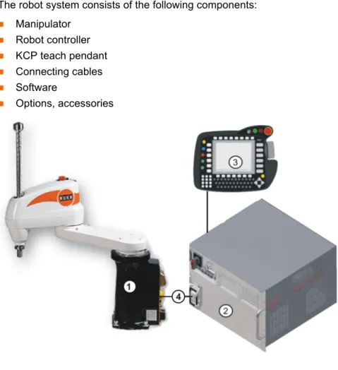
The robot system consists of the following components:
Manipulator Robot controller KCP teach pendant Connecting cables Software Options, accessories
1.2
Description of the KR 5 scara robot
Overview The robot is a 4-axis jointed-arm robot made of cast light alloy. All motor units and current-carrying cables are protected against dirt and moisture beneath screwed-on cover plates.
The robot consists of the following principal components:
Arm Link arm Base frame
Electrical installations Spindle
Fig. 1-1: Example of a robot system
1 Robot 3 Teach pendant (KCP) 2 Robot controller 4 Connecting cable
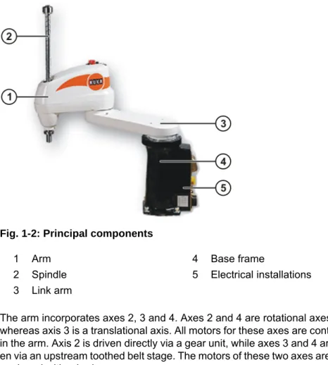
Arm The arm incorporates axes 2, 3 and 4. Axes 2 and 4 are rotational axes, whereas axis 3 is a translational axis. All motors for these axes are contained in the arm. Axis 2 is driven directly via a gear unit, while axes 3 and 4 are driv-en via an upstream toothed belt stage. The motors of these two axes are each equipped with a brake.
The mounting flange can be attached to the interface of axis 4.
Depending on the travel of the translational axis 3, the robot type is specified as Z200 or Z320. Z200 stands for a travel of 200 mm, and Z320 for a travel of 320 mm.
The arm also accommodates the 10-contact circular connector of the wrist I/O cable.
Link arm The link arm is a hollow structural element which is mounted on the base frame and screwed to the drive elements of the arm. The supply lines and sig-nal cables for the drives of axes 2 and 4, and the lines of the energy supply system (wrist I/O cable and compressed air lines) are routed through the link arm.
Base frame The base frame is the base of the robot. It houses the motor for axis 1. It con-stitutes the interface for the connecting cables between the robot, the robot controller and the energy supply system. All connecting cables are accommo-dated at the rear of the base frame. The base frame houses the backup bat-teries for backing up the axis data of the position sensing system.
Fig. 1-2: Principal components
1 Arm 4 Base frame
2 Spindle 5 Electrical installations 3 Link arm
2 Technical data
2
Technical data
2.1
Basic data
Basic data Pneumatic interface Vibration stress Ambient temper-ature Type KR 5 scara R350 KR 5 scara R550 Number of axes 4 Volume of working envelope KR 5 scara R350-Z200: 0.064 m 3 KR 5 scara R350-Z320: 0.102 m3 KR 5 scara R550-Z200: 0.165 m3 KR 5 scara R550-Z320: 0.264 m3 Repeatability (ISO 9283) KR 5 scara R350: ±0.015 mm KR 5 scara R550: ±0.020 mm Working enveloperef-erence point
Intersection of axes 3 and 4 Weight approx. 20 kg
Principal dynamic loads
See “Loads acting on the mounting base” Protection
classifica-tion of the robot
IP 40, ready for operation, with connecting cables plugged in (according to EN 60529) Sound level < 75 dB (A) outside the working envelope Mounting position Floor
Surface finish, paint-work
Plastic: white, paintwork: white, base frame: black
Operating pressure, infeed
0.05 to 0.35 MPa Max. pressure 0.59 MPa
Operation No permanent vibration stress permissible Brief, one-off: 0.5 g
Storage and transpor-tation
Brief, one-off: 3 g
Operation 0 °C to +40 °C (273 K to 313 K) Relative air humidity ≤ 90% No condensation permissible. Storage and
transpor-tation
-10 °C to +60 °C (263 K to 333 K) Relative air humidity ≤ 75% No condensation permissible.
Ambient condi-tions
Connecting cables
Cable lengths: 4 m, 6 m, 12 m
The connecting cables consist of the motor/data cable and the wrist I/O cable. The following connector designations and connections are used:
For detailed specifications of the connecting cables, see
2.2
Axis data
The data are valid for the floor-mounted KR 5 scara R350 and KR 5 scara R550 robots.
Axis data
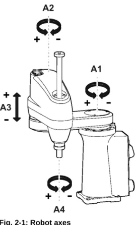
The direction of motion and the arrangement of the individual axes may be not-ed from the following diagram.
Operation Free from inflammable dust, gases and
liq-uids
Free from aggressive and corrosive gases and liquids
Free from flying parts Free from spraying liquids
Free from electromagnetic loads, e.g. from
welding equipment or high-frequency con-verters
Cable designation Connector designation
Robot controller - Robot Motor/data cable X20 - CN22 Harting circular connector Wrist I/O cable X32 - CN20 D-Sub circular connector Ground conductor PE M5 cable lug at each end
Axis Range of motion, software-limited
Speed with rated payload 5 kg 1 +/-155° 525°/s with R350 450°/s with R550 2 +/-145° 525°/s with R350 720°/s with R550 3 with Z200: +246 mm / +46 mm with Z320: +246 mm / -74 mm 2,000 mm/s 4 +/-358° 2,400°/s
2 Technical data
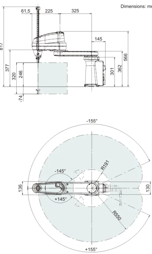
Working envelope
The following diagrams show the shape and size of the working envelopes. Fig. 2-1: Robot axes
2 Technical data
2 Technical data
2.3
Payloads
Payloads
Fig. 2-5: Working envelope KR 5 scara R550 Z320
Robot KR 5 scara
Rated payload 5 kg
Distance of the load center of gravity Lx 100 mm Distance of the load center of gravity Ly 0 mm
Distance of the load center of gravity Lz 80 mm
Load center of gravity P
For all payloads, the load center of gravity refers to the distance from the face of the mounting flange on axis 4.
Payload diagram Permissible mass inertia at the design point (Lx, Ly, Lz) is 0.1 kgm².
Supplementary load
The robot cannot carry supplementary loads. Fig. 2-6: Payload on the robot
1 FLANGE coordinate system 2 Load center of gravity 3 Robot
4 Distances LX, LY, LZ of the load center of gravity
Fig. 2-7: Payload diagram
This loading curve corresponds to the maximum load ca-pacity. Both values (payload and mass moment of iner-tia) must be checked in all cases. Exceeding this capacity will reduce the service life of the robot and overload the motors and the gears; in any such case the KUKA Roboter GmbH must be consulted beforehand.
The values determined here are necessary for planning the robot application. For commissioning the robot, additional input data are required in accor-dance with operating and programming instructions of the KUKA System Software.
The mass inertia must be verified using KUKA.Load. It is imperative for the load data to be entered in the robot controller!
2 Technical data
2.3.1 Mounting flange (optional)
The mounting flange can be made by the user. For this, the following dimen-sions must be taken into consideration.
2.4
Loads acting on the foundation
Loads acting on the foundation
The specified forces and moments already include the payload and the inertia force (weight) of the robot.
The mounting flange is not included in the scope of supply of the ro-bot.
Mounting flange DIN/ISO 9409-1-A31,5 Strength class 10.9
Screw size M5.5
Grip length 1.5 x nominal diameter Depth of engagement 6 mm
Locating element 5 H7
Fig. 2-8: Mounting flange (optional)
2.5
Additional data
Accessories Only accessories authorized and offered by KUKA may be used for this robot. All items of equipment must possess the appropriate certification and declara-tions of conformity.
Fastening threads
The fastening holes serve for fastening the covers, axis range limitations or ca-ble harnesses.
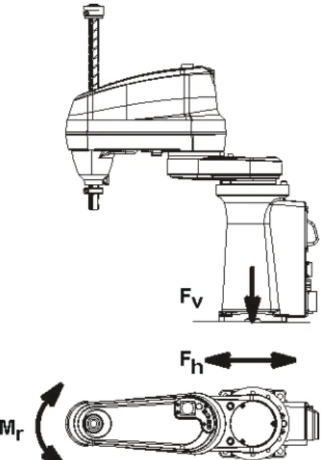
Fig. 2-10: Loads acting on the mounting base
Type of load Force/torque/mass Fv = vertical force Fvmax = 200 N
Fh = horizontal force Fhmax = 3,600 N with R350
Fhmax = 3,900 N with R550 Mr = torque Mrmax = 1,300 Nm
Total mass for load acting on the mounting base
25 kg
Robot 20 kg
Total load (suppl. load on arm + rated payload)
5 kg
2 Technical data
2.6
Plates and labels
Plates and labels The following plates, labels and signs are attached to the robot. They must not be removed or rendered illegible. Illegible plates, labels and signs must be re-placed.
1 4 holes, M3, 6 mm deep 2 Arm
3 Link arm
3 Safety
3
Safety
3.1
General
3.1.1 Liability
The device described in this document is either an industrial robot or a com-ponent thereof.
Components of the industrial robot:
Manipulator Robot controller
Teach pendant Connecting cables
External axes (optional)
e.g. linear unit, turn-tilt table, positioner
Software
Options, accessories
The industrial robot is built using state-of-the-art technology and in accor-dance with the recognized safety rules. Nevertheless, misuse of the industrial robot may constitute a risk to life and limb or cause damage to the industrial robot and to other material property.
The industrial robot may only be used in perfect technical condition in accor-dance with its intended use and only by safety-conscious persons who are ful-ly aware of the risks involved in its operation. Use of the industrial robot is subject to compliance with this document and with the declaration of incorpo-ration supplied together with the industrial robot. Any functional disorders af-fecting the safety of the industrial robot must be rectified immediately. Safety
infor-mation
Safety information cannot be held against KUKA Roboter GmbH. Even if all safety instructions are followed, this is not a guarantee that the industrial robot will not cause personal injuries or material damage.
No modifications may be carried out to the industrial robot without the autho-rization of KUKA Roboter GmbH. Additional components (tools, software, etc.), not supplied by KUKA Roboter GmbH, may be integrated into the indus-trial robot. The user is liable for any damage these components may cause to the industrial robot or to other material property.
In addition to the Safety chapter, this document contains further safety instruc-tions. These must also be observed.
3.1.2 Intended use of the industrial robot
The industrial robot is intended exclusively for the use designated in the “Pur-pose” chapter of the operating instructions or assembly instructions.
Using the industrial robot for any other or additional purpose is considered im-permissible misuse. The manufacturer cannot be held liable for any damage resulting from such use. The risk lies entirely with the user.
Operating the industrial robot and its options within the limits of its intended use also involves observance of the operating and assembly instructions for
Further information is contained in the “Purpose” chapter of the oper-ating instructions or assembly instructions of the industrial robot.
the individual components, with particular reference to the maintenance spec-ifications.
Misuse Any use or application deviating from the intended use is deemed to be imper-missible misuse. This includes e.g.:
Transportation of persons and animals
Use as a climbing aid
Operation outside the permissible operating parameters
Use in potentially explosive environments Operation without additional safeguards
Outdoor operation
3.1.3 EC declaration of conformity and declaration of incorporation
This industrial robot constitutes partly completed machinery as defined by the EC Machinery Directive. The industrial robot may only be put into operation if the following preconditions are met:
The industrial robot is integrated into a complete system.
Or: The industrial robot, together with other machinery, constitutes a com-plete system.
Or: All safety functions and safeguards required for operation in the com-plete machine as defined by the EC Machinery Directive have been added to the industrial robot.
The complete system complies with the EC Machinery Directive. This has been confirmed by means of an assessment of conformity.
Declaration of conformity
The system integrator must issue a declaration of conformity for the complete system in accordance with the Machinery Directive. The declaration of confor-mity forms the basis for the CE mark for the system. The industrial robot must be operated in accordance with the applicable national laws, regulations and standards.
The robot controller is CE certified under the EMC Directive and the Low Volt-age Directive.
Declaration of incorporation
The industrial robot as partly completed machinery is supplied with a declara-tion of incorporadeclara-tion in accordance with Annex II B of the EC Machinery Direc-tive 2006/42/EC. The assembly instructions and a list of essential
requirements complied with in accordance with Annex I are integral parts of this declaration of incorporation.
The declaration of incorporation declares that the start-up of the partly com-pleted machinery remains impermissible until the partly comcom-pleted machinery has been incorporated into machinery, or has been assembled with other parts to form machinery, and this machinery complies with the terms of the EC Ma-chinery Directive, and the EC declaration of conformity is present in accor-dance with Annex II A.
The declaration of incorporation, together with its annexes, remains with the system integrator as an integral part of the technical documentation of the complete machinery.
3 Safety
3.1.4 Terms used
3.2
Personnel
The following persons or groups of persons are defined for the industrial robot:
User
Personnel
User The user must observe the labor laws and regulations. This includes e.g.:
The user must comply with his monitoring obligations. The user must carry out instructions at defined intervals.
Personnel Personnel must be instructed, before any work is commenced, in the type of work involved and what exactly it entails as well as any hazards which may ex-Term Description
Axis range Range of each axis, in degrees or millimeters, within which it may move. The axis range must be defined for each axis.
Stopping distance Stopping distance = reaction distance + braking distance The stopping distance is part of the danger zone.
Workspace The manipulator is allowed to move within its workspace. The work-space is derived from the individual axis ranges.
Operator (User)
The user of the industrial robot can be the management, employer or delegated person responsible for use of the industrial robot.
Danger zone The danger zone consists of the workspace and the stopping distances. KCP The KCP (KUKA Control Panel) teach pendant has all the operator con-trol and display functions required for operating and programming the industrial robot.
Manipulator The robot arm and the associated electrical installations Safety zone The safety zone is situated outside the danger zone.
Stop category 0 The drives are deactivated immediately and the brakes are applied. The manipulator and any external axes (optional) perform path-oriented braking.
Note: This stop category is called STOP 0 in this document.
Stop category 1 The manipulator and any external axes (optional) perform path-main-taining braking. The drives are deactivated after 1 s and the brakes are applied.
Note: This stop category is called STOP 1 in this document. Stop category 2 The drives are not deactivated and the brakes are not applied. The
manipulator and any external axes (optional) are braked with a normal braking ramp.
Note: This stop category is called STOP 2 in this document. System integrator
(plant integrator)
System integrators are people who safely integrate the industrial robot into a complete system and commission it.
T1 Test mode, Manual Reduced Velocity (<= 250 mm/s) T2 Test mode, Manual High Velocity (> 250 mm/s permissible)
External axis Motion axis which is not part of the manipulator but which is controlled using the robot controller, e.g. KUKA linear unit, turn-tilt table, Posiflex.
All persons working with the industrial robot must have read and un-derstood the industrial robot documentation, including the safety chapter.
ist. Instruction must be carried out regularly. Instruction is also required after particular incidents or technical modifications.
Personnel includes:
System integrator
Operators, subdivided into:
Start-up, maintenance and service personnel
Operating personnel Cleaning personnel
System integrator The industrial robot is safely integrated into a complete system by the system integrator.
The system integrator is responsible for the following tasks:
Installing the industrial robot
Connecting the industrial robot Performing risk assessment
Implementing the required safety functions and safeguards Issuing the declaration of conformity
Attaching the CE mark
Creating the operating instructions for the complete system Operator The operator must meet the following preconditions:
The operator must be trained for the work to be carried out.
Work on the industrial robot must only be carried out by qualified
person-nel. These are people who, due to their specialist training, knowledge and experience, and their familiarization with the relevant standards, are able to assess the work to be carried out and detect any potential hazards. Example The tasks can be distributed as shown in the following table.
Installation, exchange, adjustment, operation, maintenance and re-pair must be performed only as specified in the operating or assembly instructions for the relevant component of the industrial robot and only by personnel specially trained for this purpose.
Tasks Operator Programmer System inte-grator Switch robot controller
on/off x x x
Start program x x x
Select program x x x
Select operating mode x x x Calibration
(tool, base) x x
Master the manipulator x x
Configuration x x Programming x x Start-up x Maintenance x Repair x Decommissioning x Transportation x
3 Safety
3.3
Workspace, safety zone and danger zone
Workspaces are to be restricted to the necessary minimum size. A workspace must be safeguarded using appropriate safeguards.
The safeguards (e.g. safety gate) must be situated inside the safety zone. In the case of a stop, the manipulator and external axes (optional) are braked and come to a stop within the danger zone.
The danger zone consists of the workspace and the stopping distances of the manipulator and external axes (optional). It must be safeguarded by means of physical safeguards to prevent danger to persons or the risk of material dam-age.
3.4
Triggers for stop reactions
Triggers for stop reactions
Stop reactions of the industrial robot are triggered in response to operator ac-tions or as a reaction to monitoring funcac-tions and error messages. The follow-ing table shows the different stop reactions accordfollow-ing to the operatfollow-ing mode that has been set.
STOP 0, STOP 1 and STOP 2 are the stop definitions according to DIN EN 60204-1:2006.
Work on the electrical and mechanical equipment of the industrial ro-bot may only be carried out by specially trained personnel.
Fig. 3-1: Example of axis range A1
1 Workspace 3 Stopping distance 2 Manipulator 4 Safety zone
Trigger T1, T2 AUT, AUT
EXT
Safety gate opened - STOP 1
3.5
Safety functions
3.5.1 Overview of safety functions
Safety functions:
Mode selection
Operator safety (= connection for the guard interlock)
Local EMERGENCY STOP device (= EMERGENCY STOP button on the KCP)
External EMERGENCY STOP device Enabling device
These circuits conform to the requirements of category 3 according to EN 954-1.
3.5.2 ESC safety logic
The function and triggering of the electronic safety functions are monitored by the ESC safety logic.
The ESC (Electronic Safety Circuit) safety logic is a dual-channel computer-aided safety system. It permanently monitors all connected safety-relevant components. In the event of a fault or interruption in the safety circuit, the pow-er supply to the drives is shut off, thus bringing the industrial robot to a stand-still.
The ESC safety logic triggers different stop reactions, depending on the oper-ating mode of the industrial robot.
The ESC safety logic monitors the following inputs:
Operator safety
Local EMERGENCY STOP (= EMERGENCY STOP button on the KCP)
External EMERGENCY STOP Enabling device
Operating modes Qualifying inputs
Enabling withdrawn STOP 0 -Start key released STOP 2 -“Drives OFF” key pressed STOP 0
STOP key pressed STOP 2
Operating mode changed STOP 0 Encoder error
(DSE-RDC connection broken)
STOP 0 Motion enable canceled STOP 2 Robot controller switched off
Power failure
STOP 0
Trigger T1, T2 AUT, AUT
EXT
In the absence of operational safety functions and safe-guards, the industrial robot can cause personal injury or material damage. If safety functions or safeguards are dismantled or deacti-vated, the industrial robot may not be operated.
3 Safety
3.5.3 Mode selector switch
The industrial robot can be operated in the following modes:
Manual Reduced Velocity (T1)
Manual High Velocity (T2) Automatic (AUT)
Automatic External (AUT EXT)
The operating mode is selected using the mode selector switch on the KCP. The switch is activated by means of a key which can be removed. If the key is removed, the switch is locked and the operating mode can no longer be changed.
If the operating mode is changed during operation, the drives are immediately switched off. The manipulator and any external axes (optional) are stopped with a STOP 0.
Fig. 3-2: Mode selector switch
1 T2 (Manual High Velocity) 2 AUT (Automatic)
3 AUT EXT (Automatic External) 4 T1 (Manual Reduced Velocity)
Operat-ing mode Use Velocities
T1
For test operation, pro-gramming and teach-ing
Program verification:
Programmed velocity, maxi-mum 250 mm/s
Jog mode:
Jog velocity, maximum 250 mm/ s
T2 For test operation Program verification: Programmed velocity
3.5.4 Operator safety
The operator safety input is used for interlocking physical safeguards. Safety equipment, such as safety gates, can be connected to the dual-channel input. If nothing is connected to this input, operation in Automatic mode is not possi-ble. Operator safety is not active in the test modes T1 (Manual Reduced Ve-locity) and T2 (Manual High VeVe-locity).
In the event of a loss of signal during Automatic operation (e.g. safety gate is opened), the manipulator and the external axes (optional) stop with a STOP 1. Once the signal is active at the input again, automatic operation can be re-sumed.
Operator safety can be connected via the peripheral interface on the robot controller.
3.5.5 EMERGENCY STOP device
The EMERGENCY STOP device for the industrial robot is the EMERGENCY STOP button on the KCP. The button must be pressed in the event of a haz-ardous situation or emergency.
Reactions of the industrial robot if the EMERGENCY STOP button is pressed:
Manual Reduced Velocity (T1) and Manual High Velocity (T2) modes: The drives are switched off immediately. The manipulator and any external axes (optional) are stopped with a STOP 0.
Automatic modes (AUT and AUT EXT):
The drives are switched off after 1 second. The manipulator and any ex-ternal axes (optional) are stopped with a STOP 1.
Before operation can be resumed, the EMERGENCY STOP button must be turned to release it and the stop message must be acknowledged.
AUT
For industrial robots without higher-level controllers
Only possible with a connected safety cir-cuit
Program mode: Programmed velocity
Jog mode: Not possible
AUT EXT
For industrial robots with higher-level con-trollers, e.g. PLC Only possible with a connected safety cir-cuit
Program mode:
Programmed velocity
Jog mode: Not possible
Operat-ing mode Use Velocities
It must be ensured that the operator safety signal is not automatically reset when the safeguard (e.g. safety gate) is closed, but only after an additional manual acknowledgement signal has been given. Only in this way can it be ensured that automatic operation is not resumed inadvertently while there are still persons in the danger zone, e.g. due to the safety gate closing accidentally.
Failure to observe this precaution may result in death, severe physical inju-ries or considerable damage to property.
3 Safety
3.5.6 External EMERGENCY STOP device
There must be EMERGENCY STOP devices available at every operator sta-tion that can initiate a robot mosta-tion or other potentially hazardous situasta-tion. The system integrator is responsible for ensuring this.
There must always be at least one external EMERGENCY STOP device in-stalled. This ensures that an EMERGENCY STOP device is available even when the KCP is disconnected.
External EMERGENCY STOP devices are connected via the customer inter-face. External EMERGENCY STOP devices are not included in the scope of supply of the industrial robot.
3.5.7 Enabling device
The enabling devices of the industrial robot are the enabling switches on the KCP.
There are 3 enabling switches installed on the KCP. The enabling switches have 3 positions:
Not pressed Center position Panic position
In the test modes, the manipulator can only be moved if one of the enabling switches is held in the central position. If the enabling switch is released or pressed fully down (panic position), the drives are deactivated immediately and the manipulator stops with a STOP 0.
Fig. 3-3: EMERGENCY STOP button on the KCP
1 EMERGENCY STOP button
Tools and other equipment connected to the manipulator must be integrated into the EMERGENCY STOP circuit on the system side if they could constitute a potential hazard.
Failure to observe this precaution may result in death, severe physical inju-ries or considerable damage to property.
3.6
Additional protective equipment
3.6.1 Jog mode
In the operating modes T1 (Manual Reduced Velocity) and T2 (Manual High Velocity), the robot controller can only execute programs in jog mode. This means that it is necessary to hold down an enabling switch and the Start key in order to execute a program.
If the enabling switch is released or pressed fully down (panic position), the drives are deactivated immediately and the manipulator and any external axes (optional) stop with a STOP 0.
Releasing only the Start key causes the industrial robot to be stopped with a STOP 2.
3.6.2 Software limit switches
The axis ranges of all manipulator and positioner axes are limited by means of adjustable software limit switches. These software limit switches only serve as machine protection and must be adjusted in such a way that the manipulator/ positioner cannot hit the mechanical end stops.
The software limit switches are set during commissioning of an industrial ro-bot.
The enabling switches must not be held down by adhe-sive tape or other means or manipulated in any other way.
Death, serious physical injuries or major damage to property may result.
Fig. 3-4: Enabling switches on the KCP
3 Safety
3.6.3 Labeling on the industrial robot
All plates, labels, symbols and marks constitute safety-relevant parts of the in-dustrial robot. They must not be modified or removed.
Labeling on the industrial robot consists of:
Identification plates Warning labels Safety symbols Designation labels Cable markings Rating plates 3.6.4 External safeguards
Safeguards The access of persons to the danger zone of the manipulator must be prevent-ed by means of safeguards.
Physical safeguards must meet the following requirements:
They meet the requirements of EN 953.
They prevent access of persons to the danger zone and cannot be easily circumvented.
They are sufficiently fastened and can withstand all forces that are likely
to occur in the course of operation, whether from inside or outside the en-closure.
They do not, themselves, represent a hazard or potential hazard.
The prescribed minimum clearance from the danger zone is maintained.
Safety gates (maintenance gates) must meet the following requirements:
They are reduced to an absolute minimum.
The interlocks (e.g. safety gate switches) are linked to the operator safety input of the robot controller via safety gate switching devices or safety PLC.
Switching devices, switches and the type of switching conform to the
re-quirements of category 3 according to EN 954-1.
Depending on the risk situation: the safety gate is additionally safeguarded by means of a locking mechanism that only allows the gate to be opened if the manipulator is safely at a standstill.
The button for acknowledging the safety gate is located outside the space
limited by the safeguards.
Other safety equipment
Other safety equipment must be integrated into the system in accordance with the corresponding standards and regulations.
Further information is contained in the operating and programming in-structions.
Further information is contained in the technical data of the operating instructions or assembly instructions of the components of the indus-trial robot.
Further information is contained in the corresponding standards and regulations. These also include EN 953.
3.7
Overview of operating modes and safety functions
The following table indicates the operating modes in which the safety functions are active.
3.8
Safety measures
3.8.1 General safety measures
The industrial robot may only be used in perfect technical condition in accor-dance with its intended use and only by safety-conscious persons. Operator errors can result in personal injury and damage to property.
It is important to be prepared for possible movements of the industrial robot even after the robot controller has been switched off and locked. Incorrect in-stallation (e.g. overload) or mechanical defects (e.g. brake defect) can cause the manipulator or external axes to sag. If work is to be carried out on a switched-off industrial robot, the manipulator and external axes must first be moved into a position in which they are unable to move on their own, whether the payload is mounted or not. If this is not possible, the manipulator and ex-ternal axes must be secured by appropriate means.
KCP The user must ensure that the industrial robot is only operated with the KCP by authorized persons.
If more than one KCP is used in the overall system, it must be ensured that each KCP is unambiguously assigned to the corresponding industrial robot. They must not be interchanged.
Safety functions T1 T2 AUT AUT EXT Operator safety - - active active EMERGENCY STOP device active active active active Enabling device active active - -Reduced velocity during
pro-gram verification active - -
-Jog mode active active -
-Software limit switches active active active active
In the absence of operational safety functions and safe-guards, the industrial robot can cause personal injury or material damage. If safety functions or safeguards are dismantled or deacti-vated, the industrial robot may not be operated.
Standing underneath the robot arm can cause death or serious physical injuries. For this reason, standing un-derneath the robot arm is prohibited!
The motors reach temperatures during operation which can cause burns to the skin. Contact must be avoided. Appropriate safety precautions must be taken, e.g. protective gloves must be worn.
3 Safety
External keyboard, external mouse
An external keyboard and/or external mouse may only be used if the following conditions are met:
Start-up or maintenance work is being carried out. The drives are switched off.
There are no persons in the danger zone.
The KCP must not be used as long as an external keyboard and/or external mouse are connected.
The external keyboard and/or external mouse must be removed as soon as the start-up or maintenance work is completed or the KCP is connected. Faults The following tasks must be carried out in the case of faults in the industrial
robot:
Switch off the robot controller and secure it (e.g. with a padlock) to prevent
unauthorized persons from switching it on again.
Indicate the fault by means of a label with a corresponding warning (tag-out).
Keep a record of the faults.
Eliminate the fault and carry out a function test.
Modifications After modifications to the industrial robot, checks must be carried out to ensure the required safety level. The valid national or regional work safety regulations must be observed for this check. The correct functioning of all safety circuits must also be tested.
New or modified programs must always be tested first in Manual Reduced Ve-locity mode (T1).
After modifications to the industrial robot, existing programs must always be tested first in Manual Reduced Velocity mode (T1). This applies to all compo-nents of the industrial robot and includes modifications to the software and configuration settings.
3.8.2 Transportation
Manipulator The prescribed transport position of the manipulator must be observed. Trans-portation must be carried out in accordance with the operating instructions or assembly instructions of the manipulator.
Robot controller The robot controller must be transported and installed in an upright position. Avoid vibrations and impacts during transportation in order to prevent damage to the robot controller.
Transportation must be carried out in accordance with the operating instruc-tions or assembly instrucinstruc-tions of the robot controller.
External axis (optional)
The prescribed transport position of the external axis (e.g. KUKA linear unit, turn-tilt table, etc.) must be observed. Transportation must be carried out in ac-cordance with the operating instructions or assembly instructions of the exter-nal axis.
The operator must ensure that decoupled KCPs are im-mediately removed from the system and stored out of sight and reach of personnel working on the industrial robot. This serves to prevent operational and non-operational EMERGENCY STOP facilities from becoming interchanged.
Failure to observe this precaution may result in death, severe physical inju-ries or considerable damage to property.
3.8.3 Start-up and recommissioning
Before starting up systems and devices for the first time, a check must be car-ried out to ensure that the systems and devices are complete and operational, that they can be operated safely and that any damage is detected.
The valid national or regional work safety regulations must be observed for this check. The correct functioning of all safety circuits must also be tested.
Function test The following tests must be carried out before start-up and recommissioning: General test:
It must be ensured that:
The industrial robot is correctly installed and fastened in accordance with the specifications in the documentation.
There are no foreign bodies or loose parts on the industrial robot. All required safety equipment is correctly installed and operational.
The power supply ratings of the industrial robot correspond to the local
supply voltage and mains type.
The ground conductor and the equipotential bonding cable are sufficiently rated and correctly connected.
The connecting cables are correctly connected and the connectors are
locked.
Test of safety-oriented circuits:
A function test must be carried out for the following safety-oriented circuits to ensure that they are functioning correctly:
Local EMERGENCY STOP device (= EMERGENCY STOP button on the
KCP)
External EMERGENCY STOP device (input and output)
Enabling device (in the test modes) Operator safety (in the automatic modes)
Qualifying inputs (if connected)
All other safety-relevant inputs and outputs used
The passwords for logging onto the KUKA System Software as “Ex-pert” and “Administrator” must be changed before start-up and must only be communicated to authorized personnel.
The robot controller is preconfigured for the specific in-dustrial robot. If cables are interchanged, the manipula-tor and the external axes (optional) may receive incorrect data and can thus cause personal injury or material damage. If a system consists of more than one manipulator, always connect the connecting cables to the manipulators and their corresponding robot controllers.
If additional components (e.g. cables), which are not part of the scope of supply of KUKA Roboter GmbH, are integrated into the industrial robot, the user is responsible for ensuring that these components do not adversely affect or disable safety functions.
If the internal cabinet temperature of the robot controller differs greatly from the ambient temperature, condensa-tion can form, which may cause damage to the electrical components. Do not put the robot controller into operation until the internal temperature of the cabinet has adjusted to the ambient temperature.
3 Safety
Test of reduced velocity control: This test is to be carried out as follows:
1. Program a straight path with the maximum possible velocity. 2. Calculate the length of the path.
3. Execute the path in T1 mode with the override set to 100% and time the motion with a stopwatch.
4. Calculate the velocity from the length of the path and the time measured for execution of the motion.
Control of reduced velocity is functioning correctly if the following results are achieved:
The calculated velocity does not exceed 250 mm/s.
The robot executes the path as programmed (i.e. in a straight line, without
deviations).
Machine data It must be ensured that the rating plate on the robot controller has the same machine data as those entered in the declaration of incorporation. The ma-chine data on the rating plate of the manipulator and the external axes (option-al) must be entered during start-up.
3.8.4 Virus protection and network security
The user of the industrial robot is responsible for ensuring that the software is always safeguarded with the latest virus protection. If the robot controller is in-tegrated into a network that is connected to the company network or to the In-ternet, it is advisable to protect this robot network against external risks by means of a firewall.
3.8.5 Manual mode
Manual mode is the mode for setup work. Setup work is all the tasks that have to be carried out on the industrial robot to enable automatic operation. Setup work includes:
Jog mode Teach
Programming Program verification
It must be ensured that no persons are present within the danger zone during path execution. Death or severe physical injuries may result.
The industrial robot must not be moved if incorrect ma-chine data are loaded. Death, severe physical injuries or considerable damage to property may otherwise result. The correct machine data must be loaded.
For optimal use of our products, we recommend that our customers carry out a regular virus scan. Information about security updates can be found at www.kuka.com.
The following must be taken into consideration in manual mode:
If the drives are not required, they must be switched off to prevent the ma-nipulator or the external axes (optional) from being moved unintentionally. New or modified programs must always be tested first in Manual Reduced Velocity mode (T1).
The manipulator, tooling or external axes (optional) must never touch or project beyond the safety fence.
Workpieces, tooling and other objects must not become jammed as a
re-sult of the industrial robot motion, nor must they lead to short-circuits or be liable to fall off.
All setup work must be carried out, where possible, from outside the safe-guarded area.
If the setup work has to be carried out inside the safeguarded area, the follow-ing must be taken into consideration:
In Manual Reduced Velocity mode (T1):
If it can be avoided, there must be no other persons inside the safeguard-ed area.
If it is necessary for there to be several persons inside the safeguarded ar-ea, the following must be observed:
Each person must have an enabling device.
All persons must have an unimpeded view of the industrial robot. Eye-contact between all persons must be possible at all times.
The operator must be so positioned that he can see into the danger area
and get out of harm’s way. In Manual High Velocity mode (T2):
This mode may only be used if the application requires a test at a velocity
higher than Manual Reduced Velocity.
Teaching and programming are not permissible in this operating mode.
Before commencing the test, the operator must ensure that the enabling
devices are operational.
The operator must be positioned outside the danger zone.
There must be no other persons inside the safeguarded area. It is the
re-sponsibility of the operator to ensure this. 3.8.6 Simulation
Simulation programs do not correspond exactly to reality. Robot programs cre-ated in simulation programs must be tested in the system in Manual Reduced Velocity mode (T1). It may be necessary to modify the program.
3.8.7 Automatic mode
Automatic mode is only permissible in compliance with the following safety measures:
All safety equipment and safeguards are present and operational. There are no persons in the system.
The defined working procedures are adhered to.
If the manipulator or an external axis (optional) comes to a standstill for no ap-parent reason, the danger zone must not be entered until an EMERGENCY STOP has been triggered.
3 Safety
3.8.8 Maintenance and repair
After maintenance and repair work, checks must be carried out to ensure the required safety level. The valid national or regional work safety regulations must be observed for this check. The correct functioning of all safety circuits must also be tested.
The purpose of maintenance and repair work is to ensure that the system is kept operational or, in the event of a fault, to return the system to an operation-al state. Repair work includes troubleshooting in addition to the actuoperation-al repair itself.
The following safety measures must be carried out when working on the indus-trial robot:
Carry out work outside the danger zone. If work inside the danger zone is necessary, the user must define additional safety measures to ensure the safe protection of personnel.
Switch off the industrial robot and secure it (e.g. with a padlock) to prevent
it from being switched on again. If it is necessary to carry out work with the robot controller switched on, the user must define additional safety mea-sures to ensure the safe protection of personnel.
If it is necessary to carry out work with the robot controller switched on, this may only be done in operating mode T1.
Label the system with a sign indicating that work is in progress. This sign
must remain in place, even during temporary interruptions to the work.
The EMERGENCY STOP systems must remain active. If safety functions or safeguards are deactivated during maintenance or repair work, they must be reactivated immediately after the work is completed.
Faulty components must be replaced using new components with the same article numbers or equivalent components approved by KUKA Roboter GmbH for this purpose.
Cleaning and preventive maintenance work is to be carried out in accordance with the operating instructions.
Robot controller Even when the robot controller is switched off, parts connected to peripheral devices may still carry voltage. The external power sources must therefore be switched off if work is to be carried out on the robot controller.
The ESD regulations must be adhered to when working on components in the robot controller.
Voltages in excess of 50 V (up to 600 V) can be present in various components for several minutes after the robot controller has been switched off! To prevent life-threatening injuries, no work may be carried out on the industrial robot in this time.
Water and dust must be prevented from entering the robot controller. Hazardous
substances
The following safety measures must be carried out when handling hazardous substances:
Avoid prolonged and repeated intensive contact with the skin.
Avoid breathing in oil spray or vapors. Clean skin and apply skin cream.
To ensure safe use of our products, we recommend that our custom-ers regularly request up-to-date safety data sheets from the manufac-turers of hazardous substances.
3.8.9 Decommissioning, storage and disposal
The industrial robot must be decommissioned, stored and disposed of in ac-cordance with the applicable national laws, regulations and standards. 3.8.10 Safety measures for “single point of control”
Overview If certain components in the industrial robot are operated, safety measures must be taken to ensure complete implementation of the principle of “single point of control”.
Components:
Submit interpreter
PLC
OPC Server
Remote control tools External keyboard/mouse
Since only the system integrator knows the safe states of actuators in the pe-riphery of the robot controller, it is his task to set these actuators to a safe state, e.g. in the event of an EMERGENCY STOP.
External
keyboard/mouse
These components can be used to modify programs, outputs or other param-eters of the robot controller, without this being noticed by any persons located inside the system.
Safety measures:
Only use one operator console at each robot controller.
If the KCP is being used for work inside the system, remove any keyboard
and mouse from the robot controller beforehand. OPC server,
remote control tools
These components can be used with write access to modify programs, outputs or other parameters of the robot controller, without this being noticed by any persons located inside the system.
Safety measures:
KUKA stipulates that these components are to be used exclusively for
di-agnosis and visualization.
Programs, outputs or other parameters of the robot controller must not be modified using these components.
Submit inter-preter, PLC
If motions, (e.g. drives or grippers) are controlled with the Submit interpreter or the PLC via the I/O system, and if they are not safeguarded by other means, then this control will take effect even in T1 and T2 modes or while an EMER-GENCY STOP is active.
If variables that affect the robot motion (e.g. override) are modified with the Submit interpreter or the PLC, this takes effect even in T1 and T2 modes or while an EMERGENCY STOP is active.
Safety measures:
Do not modify safety-relevant signals and variables (e.g. operating mode, EMERGENCY STOP, safety gate contact) via the Submit interpreter or PLC.
The implementation of additional safety measures may be required. This must be clarified for each specific application; this is the respon-sibility of the system integrator, programmer or user of the system.
3 Safety
If modifications are nonetheless required, all safety-relevant signals and variables must be linked in such a way that they cannot be set to a dan-gerous state by the Submit interpreter or PLC.
3.9
Applied norms and regulations
Name Definition Edition
2006/42/EC Machinery Directive:
Directive 2006/42/EC of the European Parliament and of the Council of 17 May 2006 on machinery, and amending Directive 95/16/EC (recast)
2006
2004/108/EC EMC Directive:
Directive 2004/108/EC of the European Parliament and of the Council of 15 December 2004 on the approximation of the laws of the Member States relating to electromagnetic compatibility and repealing Directive 89/336/EEC
2004
EN ISO 13850 Safety of machinery:
Emergency stop - Principles for design
2008 EN ISO 12100-1 Safety of machinery:
Basic concepts, general principles for design - Part 1: Basic terminology, methodology
2003
EN ISO 12100-2 Safety of machinery:
Basic concepts, general principles for design - Part 2: Technical principles
2003
EN ISO 10218-1 Industrial robots: Safety
2008 EN 954-1 Safety of machinery:
Safety-related parts of control systems - Part 1: General principles of design
1997
EN 614-1 Safety of machinery:
Ergonomic design principles - Part 1: Terms and general principles
2006
EN 61000-6-2 Electromagnetic compatibility (EMC):
Part 6-2: Generic standards; Immunity for industrial envi-ronments
2005
EN 61000-6-4 Electromagnetic compatibility (EMC):
Part 6-4: Generic standards; Emission standard for indus-trial environments
2007
EN 60204-1 Safety of machinery:
Electrical equipment of machines - Part 1: General requirements
4 Planning
4
Planning
4.1
Mounting base
Description The robot is fastened to the mounting base with 4 bolts. A suitable steel con-struction can be used as the mounting base. The mounting surface must be at least 20 mm thick. It must be ensured that the steel structure is able to with-stand safely and permanently the dynamic loads (>>> 2.4 "Loads acting on the foundation" Page 15) to which it is subjected.
In order to fasten the robot to a concrete foundation, a suitable steel plate must be prepared and fastened to the concrete foundation.
The connecting cables to the robot controller must be installed in a cable duct. If required, additional measures must be taken to ensure electromagnetic compatibility (EMC).
Hole pattern The following holes must be used for mounting the robot.
4.2
Instructions for mechanical axis range limitation
Description The robot’s working envelope can be reduced to the required minimum in axes 1 to 3 using mechanical axis range limitation systems.
In order to be able to use the mechanical axis range limitations, it is necessary to construct it. Instructions are supplied.
Installation, connection and start-up of the robot must be carried out in accordance with the applicable national laws and regulations. The robot may only be started up if the applicable regulations have been observed.
Fig. 4-1: Hole pattern for KR 5 scara
If the mechanical axis range limits are changed, the robot could collide with its end stops, resulting in damage to the robot and its tooling. The software limit switches must be set to a position at least 2 to 3° in front of the axis range limits.
4.2.1 Instructions for mechanical axis range limitation on axis 1
Description Two screws are used to limit the axis range for axis 1.
The numbers 1-11 stand for the positions of the limit stops. Axis Mechanical axis range limitation
1 2 screws
(>>> 4.2.1 "Instructions for mechanical axis range limitation on axis 1" Page 40)
2 1 plate
(>>> 4.2.2 "Instructions for mechanical axis range limitation on axis 2" Page 41)
3 Stop collar and 2 screws
(>>> 4.2.3 "Instructions for mechanical axis range limitation on axis 3" Page 41)
Axis range limitation Description
2 screws M8x12-10.9 Allen screws
Tightening torque MA = 19.6 ±3.9 Nm
Fig. 4-2: Stop positions for axis 1
Item Axis limit + Axis limit - Item Axis limit + Axis limit
-A 158° - A´ - -158° B 128° - B´ - -128° C 98° 142° C´ -142° -98° D 68° 112° D´ -112° -68° E 38° 82° E´ -82° -38° F 8° 52° F´ -52° -8°
4 Planning
4.2.2 Instructions for mechanical axis range limitation on axis 2
Description A plate is used to limit the axis range for axis 2.
4.2.3 Instructions for mechanical axis range limitation on axis 3
Description A stop collar and 2 screws are used to limit the axis range for axis 3.
Axis 1 must not be moved between positions A and A´ to avoid damage to the energy supply system. Do not re-move the screw at position 1.
Axis range limitation Description Plate Material: S45C
Tightening torque MA = 9.8 ±1.9 Nm
Fig. 4-3: Axis range limitation, axis 2
1 Link arm
2 Mechanical axis range limitation, axis 2 3 Arm
Axis range limitation Description Stop collar Material: S45C
Surface treatment: currentless nickel plat-ing
2 screws M5x18-10.9 Allen screws
Fig. 4-4: Mechanical axis range limitation, axis 3
1 Mechanical axis range limitation, axis 3
Robot A [mm] B [mm] C [mm] D [mm]
5 Transportation
5
Transportation
5.1
Transporting the robot
It must be ensured that the robot is stable while it is being transported. The robot must remain in its transport position until it has been fastened in position. Before the robot is lifted it must be ensured that it is free from obstructions. Re-move all transport safeguards, such as nails and screws, in advance. First re-move any rust or glue on contact surfaces.
Transport position
The robot must be in the transport position (>>> Fig. 5-1 ) before it can be transported. The robot is in the transport position when the axes are in the fol-lowing positions:
Transport dimen-sions
The dimensions for the robot transport can be noted from the following figure. The position of the center of mass and the weight vary according to the spe-cific configuration. The specified dimensions refer to the robot without equip-ment. Type A1 [°] A2 [°] A3 [mm] A4 [°] KR 5 scara R350 Z200 KR 5 scara R550 Z200 0 -145 +200 0 KR 5 scara R350 Z320 KR 5 scara R550 Z320 0 -145 +246 0
Transportation The robot can be transported by 2 people (>>> Fig. 5-3 ) or by fork lift truck.
Transportation by fork lift truck
For transport by fork lift truck, the robot must be screwed to a pallet using 4 bolts. A Euro pallet or the pallet used for delivery is suitable for this purpose. Fig. 5-2: Transport dimensions
Type A [mm] B [mm] C [mm]
KR 5 scara R350 Z200 566 335 266 KR 5 scara R350 Z320 571 335 266 KR 5 scara R550 Z200 566 535 266 KR 5 scara R550 Z320 571 535 266
Use of unsuitable handling equipment may result in dam-age to the robot or injury to persons. Only use authorized handling equipment with a sufficient load-bearing capacity. Only transport the robot in the manner specified here.
Fig. 5-3: Transporting the robot
1 Person 1 2 Person 2
5 Transportation
6 KUKA Service
6
KUKA Service
6.1
Requesting support
Introduction The KUKA Roboter GmbH documentation offers information on operation and provides assistance with troubleshooting. For further assistance, please con-tact your local KUKA subsidiary.
Information The following information is required for processing a support request:
Model and serial number of the robot Model and serial number of the controller
Model and serial number of the linear unit (if applicable) Version of the KUKA System Software
Optional software or modifications Archive of the software
For KUKA System Software V8: instead of a conventional archive, gener-ate the special data package for fault analysis (via KrcDiag).
Application used
Any external axes used
Description of the problem, duration and frequency of the fault
6.2
KUKA Customer Support
Availability KUKA Customer Support is available in many countries. Please do not hesi-tate to contact us if you have any questions.
Argentina Ruben Costantini S.A. (Agency) Luis Angel Huergo 13 20 Parque Industrial
2400 San Francisco (CBA) Argentina
Tel. +54 3564 421033 Fax +54 3564 428877 ventas@costantini-sa.com Australia Headland Machinery Pty. Ltd.
Victoria (Head Office & Showroom) 95 Highbury Road Burwood Victoria 31 25 Australia Tel. +61 3 9244-3500 Fax +61 3 9244-3501 vic@headland.com.au www.headland.com.au
Belgium KUKA Automatisering + Robots N.V. Centrum Zuid 1031 3530 Houthalen Belgium Tel. +32 11 516160 Fax +32 11 526794 info@kuka.be www.kuka.be
Brazil KUKA Roboter do Brasil Ltda. Avenida Franz Liszt, 80 Parque Novo Mundo Jd. Guançã
CEP 02151 900 São Paulo SP Brazil
Tel. +55 11 69844900 Fax +55 11 62017883 info@kuka-roboter.com.br Chile Robotec S.A. (Agency)
Santiago de Chile Chile Tel. +56 2 331-5951 Fax +56 2 331-5952 robotec@robotec.cl www.robotec.cl
China KUKA Automation Equipment (Shanghai) Co., Ltd. Songjiang Industrial Zone
No. 388 Minshen Road 201612 Shanghai China Tel. +86 21 6787-1808 Fax +86 21 6787-1805 info@kuka-sha.com.cn www.kuka.cn
Germany KUKA Roboter GmbH Zugspitzstr. 140 86165 Augsburg Germany Tel. +49 821 797-4000 Fax +49 821 797-1616 info@kuka-roboter.de www.kuka-roboter.de
6 KUKA Service
France KUKA Automatisme + Robotique SAS Techvallée 6, Avenue du Parc 91140 Villebon S/Yvette France Tel. +33 1 6931660-0 Fax +33 1 6931660-1 commercial@kuka.fr www.kuka.fr
India KUKA Robotics India Pvt. Ltd. Office Number-7, German Centre, Level 12, Building No. - 9B DLF Cyber City Phase III 122 002 Gurgaon Haryana India Tel. +91 124 4635774 Fax +91 124 4635773 info@kuka.in www.kuka.in
Italy KUKA Roboter Italia S.p.A. Via Pavia 9/a - int.6 10098 Rivoli (TO) Italy Tel. +39 011 959-5013 Fax +39 011 959-5141 kuka@kuka.it www.kuka.it
Japan KUKA Robotics Japan K.K. Daiba Garden City Building 1F 2-3-5 Daiba, Minato-ku Tokyo 135-0091 Japan Tel. +81 3 6380-7311 Fax +81 3 6380-7312 info@kuka.co.jp
Korea KUKA Robotics Korea Co. Ltd.
RIT Center 306, Gyeonggi Technopark 1271-11 Sa 3-dong, Sangnok-gu Ansan City, Gyeonggi Do 426-901
Korea
Tel. +82 31 501-1451 Fax +82 31 501-1461 info@kukakorea.com
Malaysia KUKA Robot Automation Sdn Bhd South East Asia Regional Office No. 24, Jalan TPP 1/10
Taman Industri Puchong 47100 Puchong Selangor Malaysia Tel. +60 3 8061-0613 or -0614 Fax +60 3 8061-7386 info@kuka.com.my
Mexico KUKA de Mexico S. de R.L. de C.V. Rio San Joaquin #339, Local 5 Colonia Pensil Sur
C.P. 11490 Mexico D.F. Mexico
Tel. +52 55 5203-8407 Fax +52 55 5203-8148 info@kuka.com.mx
Norway KUKA Sveiseanlegg + Roboter Bryggeveien 9 2821 Gjövik Norway Tel. +47 61 133422 Fax +47 61 186200 geir.ulsrud@kuka.no
Austria KUKA Roboter Austria GmbH Vertriebsbüro Österreich Regensburger Strasse 9/1 4020 Linz Austria Tel. +43 732 784752 Fax +43 732 793880 office@kuka-roboter.at www.kuka-roboter.at
Poland KUKA Roboter Austria GmbH
Spółka z ograniczoną odpowiedzialnością Oddział w Polsce Ul. Porcelanowa 10 40-246 Katowice Poland Tel. +48 327 30 32 13 or -14 Fax +48 327 30 32 26 ServicePL@kuka-roboter.de
6 KUKA Service
Portugal KUKA Sistemas de Automatización S.A. Rua do Alto da Guerra n° 50
Armazém 04 2910 011 Setúbal Portugal Tel. +351 265 729780 Fax +351 265 729782 kuka@mail.telepac.pt Russia OOO KUKA Robotics Rus
Webnaja ul. 8A 107143 Moskau Russia Tel. +7 495 781-31-20 Fax +7 495 781-31-19 kuka-robotics.ru
Sweden KUKA Svetsanläggningar + Robotar AB A. Odhners gata 15 421 30 Västra Frölunda Sweden Tel. +46 31 7266-200 Fax +46 31 7266-201 info@kuka.se
Switzerland KUKA Roboter Schweiz AG Industriestr. 9 5432 Neuenhof Switzerland Tel. +41 44 74490-90 Fax +41 44 74490-91 info@kuka-roboter.ch www.kuka-roboter.ch
Spain KUKA Robots IBÉRICA, S.A. Pol. Industrial
Torrent de la Pastera Carrer del Bages s/n
08800 Vilanova i la Geltrú (Barcelona) Spain
Tel. +34 93 8142-353 Fax +34 93 8142-950 Comercial@kuka-e.com www.kuka-e.com
South Africa Jendamark Automation LTD (Agency) 76a York Road
North End 6000 Port Elizabeth South Africa Tel. +27 41 391 4700 Fax +27 41 373 3869 www.jendamark.co.za
Taiwan KUKA Robot Automation Taiwan Co., Ltd. No. 249 Pujong Road
Jungli City, Taoyuan County 320 Taiwan, R. O. C.
Tel. +886 3 4331988 Fax +886 3 4331948 info@kuka.com.tw www.kuka.com.tw
Thailand KUKA Robot Automation (M)SdnBhd Thailand Office
c/o Maccall System Co. Ltd.
49/9-10 Soi Kingkaew 30 Kingkaew Road Tt. Rachatheva, A. Bangpli Samutprakarn 10540 Thailand Tel. +66 2 7502737 Fax +66 2 6612355 atika@ji-net.com www.kuka-roboter.de
Czech Republic KUKA Roboter Austria GmbH
Organisation Tschechien und Slowakei Sezemická 2757/2 193 00 Praha Horní Počernice Czech Republic Tel. +420 22 62 12 27 2 Fax +420 22 62 12 27 0 support@kuka.cz
Hungary KUKA Robotics Hungaria Kft. Fö út 140 2335 Taksony Hungary Tel. +36 24 501609 Fax +36 24 477031 info@kuka-robotics.hu
6 KUKA Service
USA KUKA Robotics Corp. 22500 Key Drive Clinton Township 48036 Michigan USA Tel. +1 866 8735852 Fax +1 586 5692087 info@kukarobotics.com www.kukarobotics.com UK KUKA Automation + Robotics
Hereward Rise Halesowen B62 8AN UK Tel. +44 121 585-0800 Fax +44 121 585-0900 sales@kuka.co.uk
Index
Index
Numbers 2004/108/EC 37 2006/42/EC 37 89/336/EEC 37 95/16/EC 37 A Accessories 5, 16, 19 Additional data 16 Ambient conditions 8 Ambient temperature 7Applied norms and regulations 37 Arm 6 AUT 25 AUT EXT 25 Automatic 25 Automatic External 25 Automatic mode 34 Axis data 8 Axis range 21 B Base frame 6 Basic data 7 Brake defect 30 Braking distance 21 C CE mark 20 Cleaning work 35 Connecting cables 5, 8, 19 D Danger zone 21 Declaration of conformity 20 Declaration of incorporation 19, 20 Decommissioning 36 Description, KR 5 scara 5 Dimensions, transport 43 Disposal 36 E EC declaration of conformity 20 EMC Directive 20, 37 EMERGENCY STOP 23
EMERGENCY STOP button 24, 26, 27, 32 EMERGENCY STOP device 26, 27, 30 EMERGENCY STOP, external 24, 27, 32 EMERGENCY STOP, local 24, 32 EN 60204-1 37 EN 61000-6-2 37 EN 61000-6-4 37 EN 614-1 37 EN 954-1 37 EN ISO 10218-1 37 EN ISO 12100-1 37 EN ISO 12100-2 37 EN ISO 13850 37 Enabling device 24, 27, 30 Enabling switches 27, 28 ESC 24 External axes 19, 21 F Fastening threads 16 Faults 31 Firewall 33 Fork lift truck 44 Function test 32 G
General safety measures 30 Guard interlock 26 H Handling equipment 44 Hazardous substances 35 I Industrial robot 19
Instructions for mechanical axis range limitation 39
Instructions for mechanical axis range limitation, axis 1 40
Instructions for mechanical axis range limitation, axis 2 41
Instructions for mechanical axis range limitation, axis 3 41 Intended use 19 J Jog mode 28, 30 K KCP 5, 21, 30 Keyboard, external 31 KUKA Customer Support 47 L
Labeling 29 Liability 19 Linear unit 19 Link arm 6
Load center of gravity 14
Loads acting on the foundation 15 Low Voltage Directive 20
M
Machine data 33
Machinery Directive 20, 37 Maintenance 35
Manipulator 5, 19, 21, 23 Manual High Velocity 25 Manual mode 33
Manual Reduced Velocity 25 Mode selector switch 25