Model Based Systems
Engineering
(MBSE)
Media Study
Prepared by:
Julia Murray
May 2, 2012
Model Based Systems Engineering (MBSE) Media Study
TABLE OF CONTENTS
1.0 MODEL-BASED SYSTEMS ENGINEERING (MBSE) INITIATIVE ... 5
2.0 MBSE DEFINITIONS & ADVANTAGES ... 6
2.1 INTERNATIONAL COUNCIL ON SYSTEMS ENGINEERING (INCOSE)DEFINITION &ADVANTAGES ... 6
2.1.1 Model-Based Systems Engineering (MBSE) Definition ... 6
2.1.2 Advantage to using MBSE ... 7
2.2 SYSMLFORUM MBSEDEFINITION &ADVANTAGE ... 8
2.2.1 SysML Forum MBSE Definition ... 8
2.2.2 SysML Forum MBSE Advantage ... 8
3.0 INCOSE SYSTEMS ENGINEERING VISION 2020 ... 9
3.1 VISION 2020INTEGRATING FRAMEWORK ... 9
3.2 SYSTEMS ENGINEERING VISION ... 10
3.3 ROLE OF MBSE WITHIN SYSTEMS ENGINEERING VISION 2020 ... 12
4.0 MBSE METHODOLOGIES ... 14
4.1 INCOSEOBJECT-ORIENTED SYSTEMS ENGINEERING METHOD (OOSEM) ... 14
4.2 IBMRATIONAL TELELOGIC HARMONY-SE ... 16
4.3 IBMRATIONAL UNIFIED PROCESS FOR SYSTEMS ENGINEERING (RUP-SE) ... 17
4.4 JPLSTATE ANALYSIS (SA) ... 19
4.5 VITECH MODEL-BASED SYSTEMS ENGINEERING (MBSE)METHODOLOGY... 20
4.6 DORI OBJECT-PROCESS METHODOLOGY (OPM) ... 22
4.7 WEILKIENS SYSTEMS MODELING PROCESS (SYSMOD) ... 23
4.8 FERNANDEZ ISE&PROCESS PIPELINES IN OOARCHITECTURES (ISE&PPOOA) ... 24
5.0 MBSE MODELING LANGUAGE STANDARDS ... 26
5.1 OMGSYSMLTM ... 26
5.2 UML ... 28
6.0 MBSE SOFTWARE TOOLS ... 29
6.1 MBSETOOLS AND RELEVANCE OF OTHER “DE-FACTO”MBSE VISUAL MODELING STANDARDS ... 29
6.2 SAEARCHITECTURE ANALYSIS &DESIGN LANGUAGE (AADL) ... 29
6.3 VITECH CORE ... 30
6.4 MAGICDRAW® ... 31
6.4.1 Related MagicDraw Products and Plugins ... 32
6.5 PHOENIX INTEGRATION ... 32
6.5.1 Design Space Navigation/Optimization & Variable Sensitivity Analysis ... 33
6.5.2 ModelCenter ... 33
6.5.2.1 Benefits ... 34
6.6 IBM®RATIONAL®RHAPSODY® ... 34
6.7 ECLIPSE ... 35
6.7.1 What is Eclipse and the Eclipse Foundation? ... 35
6.7.2 A Unique Model for Open Source Development ... 36
6.7.3 About Papyrus ... 36
6.8 ISIGHT & THE SIMULIAEXECUTION ENGINE ... 36
6.8.1 Dassault Systèmes Company Information ... 36
6.8.2 SIMULIA Overview ... 36
6.8.3 Isight & SEE Overview ... 37
7.0 COMPANIES WORKING TO IMPLEMENT MBSE ... 38
7.1 LOCKHEED MARTIN ... 38
7.2 DEERE &CO ... 38
Model Based Systems Engineering (MBSE) Media Study
7.4 RAYTHEON... 38
7.5 ATAENGR ... 38
7.6 JPL ... 39
7.7 MODERN TECHNOLOGY SYSTEMS INC. ... 39
7.8 NORTHROP GRUMMAN... 39
7.9 U.S.ARMY RESEARCH,DEVELOPMENT AND ENGINEERING COMMAND ... 40
7.10 SAFCONSULTING ... 40
8.0 UNIVERSITIES ... 41
8.1 GEORGIA TECH ... 41
8.2 UNIVERSITY OF ALABAMA -HUNTSVILLE ... 41
8.3 UNIVERSITY OF MARYLAND &THE INSTITUTE FOR SYSTEMS RESEARCH ... 41
8.4 TECHNION ISRAEL INSTITUTE OF TECHNOLOGY ... 42
8.5 MASSACHUSETTS INSTITUTE OF TECHNOLOGY ... 42
8.6 STEVENS INSTITUTE OF TECHNOLOGY ... 42
8.7 TECHNICAL UNIVERSITY OF DEMARK ... 43
9.0 DOD SYSTEMS 2020 VISION ... 44
9.1 SYSTEMS 2020OBJECTIVES AND CONSTRAINTS ... 45
9.2 INTEGRATED GAME-CHANGING SOLUTION STRATEGY ... 45
9.2.1 Model Based Engineering (MBE) ... 46
9.2.1.1 Related to DoD Systems 2020 Initiative ... 47
9.2.2 Platform Based Engineering (PBE) ... 47
9.2.2.1 Related to DoD Systems 2020 Initiative ... 47
9.2.3 Capability on Demand (COD) ... 48
9.2.3.1 Related to DoD Systems 2020 Initiative ... 48
9.2.4 Trusted Systems Design (TSD)... 48
9.2.4.1 Related to DoD Systems 2020 Initiative ... 49
10.0 LEAN ENGINEERING ... 50
10.1 LEAN IMPLEMENTATION DEVELOPS FROM TPS ... 50
10.2 DIFFERENCES FROM TPS... 50
10.3 LEAN GOALS AND STRATEGY ... 51
10.4 STEPS TO ACHIEVE LEAN SYSTEMS ... 52
10.4.1 Design a simple manufacturing system ... 52
10.4.2 There is always room for Improvement ... 52
10.4.3 Continuously Improve ... 52
10.5 HOW CAN LEAN CONNECT WITH MBSE ... 53
10.5.1 Why focus on Models? ... 53
10.5.2 Why focus on Architecture? ... 53
11.0 LOOK AHEAD WHERE WE ARE GOING? ... 54
11.1 INFLUENCE OF SYSTEMS ENGINEERING PRINCIPLES IN A TECHNICAL SOCIETY ... 54
Model Based Systems Engineering (MBSE) Media Study
LIST OF TABLES & FIGURES
FIGURE 1-1:MBSEMODELING AT MULTI LEVELS OF THE SYSTEM ... 5
FIGURE 2-1:MBSEACROSS THE SYSTEM LIFE CYCLE ... 6
FIGURE 2-2:MBSEMODEL CENTRIC APPROACH ... 6
FIGURE 2-3:TRANSITION TO MBSE ... 7
FIGURE 2-4:INCOSEMBSEROADMAP ... 7
FIGURE 2-5:TECHNICAL AND BUSINESS ADVANTAGES OF AMBSEAPPROACH ... 8
FIGURE 3-1:AN INTEGRATING FRAMEWORK FOR THE SYSTEMS ENGINEERING VISION 2020 ... 10
TABLE 3-1:DRIVERS AND INHIBITORS INFLUENCING THE PRACTICE OF SYSTEMS ENGINEERING ... 11
FIGURE 3-2:CROSS-DOMAIN MODEL INTEGRATION ... 13
FIGURE 4-1:OOSEMPYRAMID -TOP-DOWN (FUNCTIONAL DECOMPOSITION)APPROACH ... 15
FIGURE 4-2:OOSEMACTIVITIES -INTEGRATION W/OBJECT-ORIENTED S/WDEVELOPMENT,H/WDEVELOPMENT, AND TEST ... 15
FIGURE 4-3:STANDARD SYSMLACTIVITY DIAGRAM ... 16
FIGURE 4-4:IBMRATIONAL TELELOGIC HARMONY-SEPROCESS ... 17
FIGURE 4-5:RUP-SE-VIEWPOINT OF SELIFECYCLE ... 18
FIGURE 4-6:RUP-SE-REQUIREMENTS ALLOCATIONS VS. DERIVED METHOD ... 18
FIGURE 4-7:MODEL- AND STATE-BASED CONTROL ARCHITECTURE ... 19
FIGURE 4-8:ELEMENTS AND RELATIONSHIPS OF STATE ANALYSIS SYNTHESIZED WITH FUNCTIONAL ANALYSIS ... 20
FIGURE 4-9:VITECH MBSEDOMAINS ... 21
FIGURE 4-10:VITECH ONION MODEL ... 21
FIGURE 4-11:EXAMPLE OF TOP LEVEL SPECIFICATION OF THE OPMMETAMODEL ... 22
FIGURE 4-12:OPMZOOMING INTO SYSTEM DEVELOPING ... 23
FIGURE 4-13:WEILKIENS SYSTEMS MODELING PROCESS (SYSMOD)METHODOLOGY ... 24
FIGURE 4-14:FERNANDEZ ISE&PROCESS PIPELINES IN OOARCHITECTURES (ISE&PPOOA)METHODOLOGY .... 25
FIGURE 5-1:RELATIONSHIP BETWEEN SYSML AND UML ... 26
FIGURE 5-2:SYSMLDIAGRAM TYPES ... 27
FIGURE 5-3:THE FOUR PILLARS OF SYSML ... 27
FIGURE 6-1:SIMPLE MODEL CONSTRUCTION ... 31
FIGURE 6-2:EXAMPLE OF COREMODEL COMMUNICATION ... 31
FIGURE 6-3:DELIVERS MULTIDISCIPLINARY DESIGN OPTIMIZATION (MDO) ... 32
FIGURE 6-4:SIMPLIFIES SYSTEM-OF-SYSTEMS (SOS)ANALYSIS ... 33
Model Based Systems Engineering (MBSE) Media Study
1.0 Model-Based Systems Engineering (MBSE) Initiative
(Source data: http://www.omgwiki.org/MBSE/doku.php#mbse_initiative_overview &
www.incose.org/enchantment/docs/07docs/07jul_4mbseroadmap.pdf)
The MBSE Initiative was initiated at the INCOSE International Workshop in 2007. Its Charter was to “Promote, advance, and institutionalize the practice of MBSE to attain the MBSE 2020 Vision through broad industry and academic involvement in:
Research Standards
Processes, Practices, & Methods Tools & Technology
Outreach, Training & Education
Additional details on this are covered in the next section.
Model Based Systems Engineering (MBSE) Media Study
2.0 MBSE Definitions & Advantages
Definitions and advantages of Model-Based Systems Engineering (MBSE) has been defined by both International Council on Systems Engineering (INCOSE) and SysML Forum and are covered below.
2.1 International Council on Systems Engineering (INCOSE) Definition &
Advantages
(Source data: http://www.incose.org/enchantment/docs/07docs/07jul_4mbseroadmap.pdf)
2.1.1 Model-Based Systems Engineering (MBSE) Definition
"Is the formalized application of modeling to support system requirements, design, analysis, verification and validation activities beginning in the conceptual design phase and continuing throughout development and later life cycle phases”, shown in Figure 2-1.
Figure 2-1: MBSE Across the System Life Cycle
MBSE is part of a long-term trend toward model-centric approaches adopted by other engineering disciplines, including mechanical, electrical and software, as depicted in Figure 2-2.
Model Based Systems Engineering (MBSE) Media Study
In particular, MBSE is expected to replace the document-centric approach that has been practiced by systems engineers in the past and to influence the future practice of systems
engineering by being fully integrated into the definition of systems
engineering processes, depicted in Figure 2-3: Transition to MBSE.
Figure 2-3: Transition to MBSE
INCOSE MBSE Roadmap is shown in Figure 2-4.
2010 2020 2025 Matu rity MBSE Capability Ad Hoc MBSE Document Centric 2010 Well Defined MBSE Institutionalized MBSE across Academia/Industry
Reduced cycle times Design optimization across broad trade space Cross domain effects based analysis System of systems
interoperability
Extending Maturity and Capability
Distributed & secure model repositories crossing multiple domains Defined MBSE theory, ontology, and formalisms
Emerging MBSE standards
Matured MBSE methods and metrics, Integrated System/HW/SW models
Architecture model integrated with Simulation, Analysis, and Visualization
•Planning & Support •Research
•Standards Development
•Processes, Practices, & Methods •Tools & Technology Enhancements •Outreach, Training & Education
Refer to activities in the following areas:
Figure 2-4: INCOSE MBSE Roadmap
2.1.2 Advantage to using MBSE
MBSE enhances the ability to capture, analyze, share, and manage the information associated with the complete specification of a product, resulting in the following benefits:
Improved communications among the development stakeholders (e.g. the customer, program management, systems engineers, hardware and software developers,
testers, and specialty engineering disciplines).
Increased ability to manage system complexity by enabling a system model to be viewed from multiple perspectives, and to analyze the impact of changes.
Improved product quality by providing an unambiguous and precise model of the system that can be evaluated for consistency, correctness, and completeness.
Enhanced knowledge capture and reuse of the information by capturing information in more standardized ways and leveraging built in abstraction mechanisms inherent in
Model Based Systems Engineering (MBSE) Media Study
model driven approaches. This in turn can result in reduced cycle time and lower maintenance costs to modify the design.
Improved ability to teach and learn systems engineering fundamentals by providing a clear and unambiguous representation of the concepts.
2.2 SysML Forum MBSE Definition & Advantage
(Source information is from: http://www.sysmlforum.com/faq/what-is-MBSE.html)
2.2.1 SysML Forum MBSE Definition
MBSE is an umbrella term that describes an approach to Systems Engineering that:
Emphasizes a system architecture modelas the primary work artifact throughout the
System Development Life Cycle (SDLC)
Combines traditional systems engineering best practices with rigorous visual modeling techniques
Typically uses the SysML as a standard visual modeling language. SysML not only supports rigorous modeling techniques among Systems Engineers, it also serves as a lingua franca among various other kinds of engineers (Software Engineers, Electrical Engineers, Mechanical Engineers, etc.) and stakeholders who need to understand MBSE work products, such as visual requirements analysis and verification, CONOPS, functional analysis and allocations, performance analysis, trade studies, and system architectures.
2.2.2 SysML Forum MBSE Advantage
MBSE offers systems engineers the following advantages over traditional document-centric Systems Engineering approaches:
Technology drivers
Technology Advantages Business Advantages
Model
Requirements
Ensure that the requirements are an integral part of the model and all other parts of the model can be traced back to requirements
Validate that you are "building the right system"...[Boeham 1984]
Model Analysis & Design
Provide a precise architectural blueprint organization by the views that are meaningful to all systems stakeholders
Verify that you are "building the system the right way" [Boeham 1984]
Model Simulation
Automate system verification and validation
Reduce errors and costs early in the lifecycle
Model Code Automate generation of production
quality code
Accelerated time to market
Model Test Automate testing Ensure system implementation
is correct and reliable
Model Based Systems Engineering (MBSE) Media Study
3.0 INCOSE Systems Engineering Vision 2020
(Source data: INCOSE Systems Engineering Vision 2020 INCOSE-TP-2004-004-02 September, 2007
http://www.incose.org/ProductsPubs/pdf/SEVision2020_20071003_v2_03.pdf)
This INCOSE Systems Engineering 2020 vision of the evolution of systems engineering began with an assessment of the current state of practice and trends, identified drivers and inhibitors, then extrapolated the future state of practice in systems engineering. This analysis was conducted in five focus areas - the Global Systems Engineering Environment, Systems and their Nature, Systems Engineering Processes, Models and Model-Based Systems Engineering, and Systems Engineering Education.
Several significant trends in the global environment are leading to the emergence of a more widespread and effective application of the systems engineering practice. There is a growing realization that systems engineering is essential to successfully design, develop and sustain the highly complex systems of the 21st century. Yet, the profession suffers from the lack of a set of unified principles, models that support a wide range of domains, and consistent
terminology and definitions. Furthermore, there is a prevailing perception that systems engineering is overly cumbersome and not readily applicable to small projects or small businesses.
One can expect a shift away from a “one size fits all” definition and application of systems engineering to a more specifically defined and precise application of systems engineering in diverse domains. The future systems engineering environment will fully support life cycle perspectives such as supply chains and system sustainment.
The following areas within the System Engineering 2020 Reports (both 2007 & 2008) are covered in this media study in more detail:
Vision 2020 integrating framework, Systems engineering vision, and
Role of MBSE within systems engineering vision 2020
3.1 Vision 2020 Integrating Framework
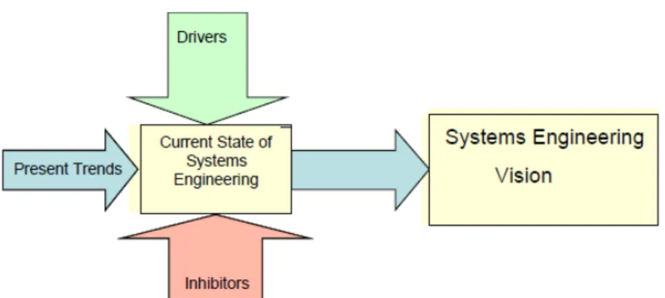
As illustrated in Figure 3-1 below, the INCOSE Systems Engineering Vision 2020 forecasts
the future state of the practice of systems engineering, extrapolated from evolutionary developments in the current state of practice and trends, and a set of drivers and inhibitors that will influence the future state. The analysis was conducted in five focus areas, as follows:
Global Systems Engineering Environment sets the international context and imperatives;
Systems and their Nature describes the scope and technical areas of the discipline; Systems Engineering Processes defines elements of the practice of the discipline; Models and Model-based Systems Engineering introduces new capability into systems
engineering practices; and,
Systems Engineering Education provides an insight into the primary source of communicating and advancing the principles and practice.
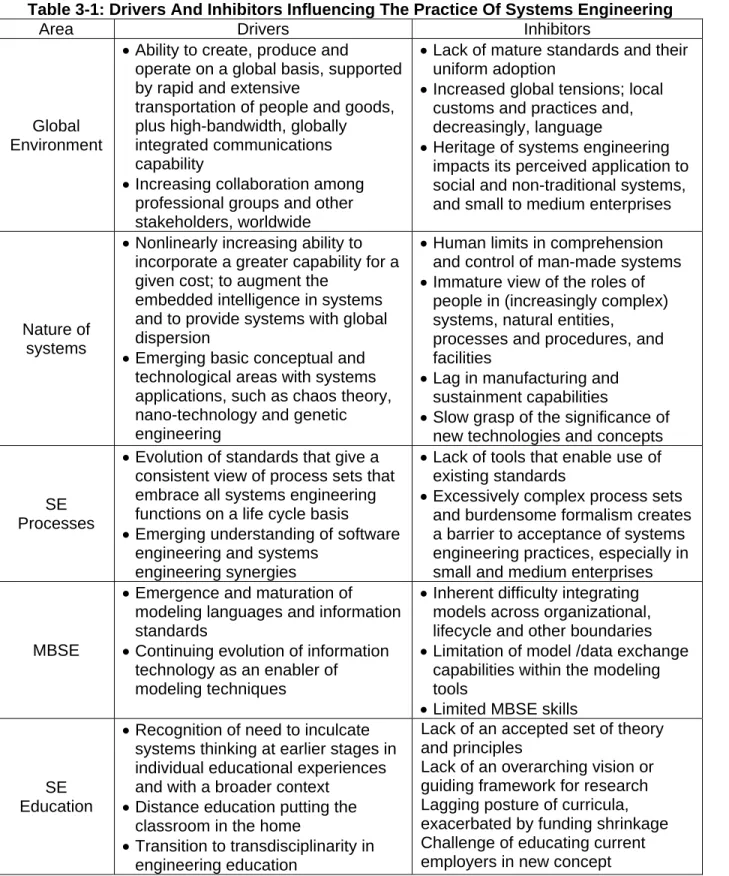
Table 3-1 contains a sampling of observed drivers and inhibitors, categorized according to each of the five focus areas, which have significant potential to influence the state of practice of systems engineering.
Model Based Systems Engineering (MBSE) Media Study
Figure 3-1: An Integrating Framework For The Systems Engineering Vision 2020
3.2 Systems Engineering Vision
The current state of systems engineering practice is evolving under the influence of the respective drivers and inhibitors called out in Table 3-1. Through a series of workshops experts in systems engineering and related fields were brought together to hypothesize about the future of systems engineering, beyond the next decade.
In a best case scenario, the experts anticipate that systems thinking and systems engineering will guide the way people think about solving problems in the next decade and systems engineering will become an established international “inter-disciplinary connector” or “meta-discipline.” Increased diversity within the stakeholder population creates the need for shared sense making through shared mental models; a need that systems engineering will satisfy. In the future systems engineering will be used to address the significant social, economic, environmental and planning issues of the day.
Additional systems engineering capabilities will be created to support the adaptation of system engineering methodology to the agile and robust operations of extended enterprises and businesses of all sizes. This will include:
Advanced systems theory application
Increased use of analytical methods and tools
Advances in engineering education with an emphasis on interdisciplinary integration Improved use/integration of engineering specialties
Improved understanding of psychology, languages and culture
Improved shared understanding of systems engineering concepts among all stakeholders
Stovepipes between disciplines will begin to blur as the benefits – diversity of ideas, lower organizational costs and greater development efficiency – of interdisciplinary integration are realized. Stakeholders will take the time to identify the characteristics (capability, culture, communication and decision making style, appetite for risk, ethics, etc.) of their global business partners.
Model Based Systems Engineering (MBSE) Media Study
Table 3-1: Drivers And Inhibitors Influencing The Practice Of Systems Engineering
Area Drivers Inhibitors
Global Environment
Ability to create, produce and
operate on a global basis, supported by rapid and extensive
transportation of people and goods, plus high-bandwidth, globally integrated communications capability
Increasing collaboration among professional groups and other stakeholders, worldwide
Lack of mature standards and their uniform adoption
Increased global tensions; local customs and practices and, decreasingly, language
Heritage of systems engineering impacts its perceived application to social and non-traditional systems, and small to medium enterprises
Nature of systems
Nonlinearly increasing ability to incorporate a greater capability for a given cost; to augment the
embedded intelligence in systems and to provide systems with global dispersion
Emerging basic conceptual and technological areas with systems applications, such as chaos theory, nano-technology and genetic engineering
Human limits in comprehension and control of man-made systems Immature view of the roles of
people in (increasingly complex) systems, natural entities,
processes and procedures, and facilities
Lag in manufacturing and sustainment capabilities
Slow grasp of the significance of new technologies and concepts
SE Processes
Evolution of standards that give a consistent view of process sets that embrace all systems engineering functions on a life cycle basis Emerging understanding of software
engineering and systems engineering synergies
Lack of tools that enable use of existing standards
Excessively complex process sets and burdensome formalism creates a barrier to acceptance of systems engineering practices, especially in small and medium enterprises
MBSE
Emergence and maturation of modeling languages and information standards
Continuing evolution of information technology as an enabler of
modeling techniques
Inherent difficulty integrating models across organizational, lifecycle and other boundaries Limitation of model /data exchange
capabilities within the modeling tools
Limited MBSE skills
SE Education
Recognition of need to inculcate systems thinking at earlier stages in individual educational experiences and with a broader context
Distance education putting the classroom in the home
Transition to transdisciplinarity in engineering education
Lack of an accepted set of theory and principles
Lack of an overarching vision or guiding framework for research Lagging posture of curricula, exacerbated by funding shrinkage Challenge of educating current employers in new concept
Model Based Systems Engineering (MBSE) Media Study
3.3 Role of MBSE within Systems Engineering Vision 2020
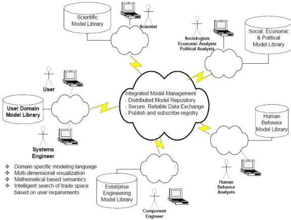
Per INCOSE Systems Engineering Vision 2020, the projected state of MBSE practice in 2020 will extend MBSE to modeling domains beyond engineering models to support complex predictive and effects-based modeling. This will include the integration of engineering models with scientific and phenomenology models, social, economic, and political models and human behavioral models. The key characteristics of MBSE in 2020 include:
Domain-specific modeling languages and visualization that enable the systems engineer to focus on modeling of the user domain
Modeling standards based on a firm mathematical foundation that support high fidelity simulation and real-world representations
Extensive reuse of model libraries, taxonomies and design patterns
Standards that support integration and management across a distributed model repository
Highly reliable and secure data exchange via published interfaces.
Domain-specific modeling languages built on the general purpose systems modeling language will increase the abstraction level to represent the user domain. Validated and specialized model libraries for specific domains will be established that can be reused across
organizations and evolved over time. A system engineer familiar with the domain will be able to rapidly search the distributed model repository and evaluate a broad trade space of
solutions based on an understanding of the user requirements and measures of effectiveness. Thus, the systems engineer will readily perform what-if analysis to assess the requirements, design, and technology impacts, and optimize the solution, using multi-dimensional
visualization capabilities.
The conceptual depiction in Figure 3-2 indicates a desired goal and direction toward
advancing capabilities for MBSE. The integrated capabilities shown will dramatically increase the application of MBSE to support marketing research, decision analysis, integration with biological system models, environmental impact analysis and the design of social systems in support of urban planning and government social programs, to name a few.
Collaborative environments will be set up quickly for new project teams and extended across global government, industry and academic teams. Management of product data throughout the lifecycle will provide improved logistics and Operations and Maintenance phase support, since design data is retained in standards-based repositories. Virtual development
environments will minimize the need for physical prototypes and will accelerate new product development while providing realistic verification against customer driven requirements.
Model Based Systems Engineering (MBSE) Media Study
Figure 3-2: Cross-Domain Model Integration
System development times will be substantially reduced relative to current practice, while improving overall system quality and availability. This will be accomplished by a combination of failure-mode avoidance and knowledge-based engineering. The application of increased computer power will enable rapid system design with models in virtual development
environments, greatly reducing the need for physical prototypes.
The breadth of applied models will not be confined to the traditional extent of dealing with the immediate system interfaces. Relationships will emerge between individual system models that are built to analyze systems across life cycles spanning decades and the social and economic models that estimate the impact of cumulative decisions on the economy and our environment. “Intelligent systems” will add significant effort to up-front systems engineering with the benefit of enabling planned change at an industry, domain, or societal level. System models and simulations will explore the impacts to our environment, society, and the
stakeholder organizations in ways that are ignored today and discovered by analysis of impacts after systems become operational.
A complete discussion of the MBSE vision must also be accompanied by realistic concerns about inhibitors to its progress such as those described in Table 3-1. Difficult technical and cultural challenges remain to be overcome in order to realize the many facets and benefits of the envisioned MBSE evolution. Meaningful progress will require both market forces and motivated visionaries inclined to take some risks in pushing the envelope to demonstrate value, exploiting opportunities and setting an example for others to follow.
Model Based Systems Engineering (MBSE) Media Study
4.0 MBSE
Methodologies
(Source data: http://www.omgwiki.org/MBSE/doku.php?id=mbse:methodology and
http://www.incose.org/productspubs/pdf/techdata/mttc/mbse_methodology_survey_2008-0610_revb-jae2.pdf)
In general, a methodology can be defined as the collection of related processes, methods, and tools used to support a specific discipline [Martin, 1996]. That more general notion of methodology can be specialized to MBSE methodology, which we characterize as the collection of related processes, methods, and tools used to support the discipline of systems engineering in a “model-based” or “model-driven” context [Estefan, 2008].
In 2007, a formal survey of candidate MBSE methodologies was published as part of the work of the INCOSE MBSE Focus Group that later was formalized as the INCOSE MBSE Initiative. In 2008, that formal survey of candidate MBSE methodologies was published under the auspices of an INCOSE technical publication. The 2008 report surveyed six (6) candidate MBSE methodologies:
INCOSE Object-Oriented Systems Engineering Method (OOSEM) IBM Rational Telelogic Harmony-SE
IBM Rational Unified Process for Systems Engineering (RUP-SE) Vitech Model-Based Systems Engineering (MBSE)
JPL State Analysis (SA)
Dori Object-Process Methodology (OPM)
Additional methodologies identified as gaps since the 2008 INCOSE Survey: Weilkiens Systems Modeling Process (SYSMOD)
Fernandez Process Pipelines in OO Architectures (PPOOA) An overview of each of these methodologies is covered below.
It should be noted that the scope of the survey report went beyond a simple survey and also documented a number of key issues related to the discipline of MBSE, including the following: differentiating processes, methods, and tools; characterizing the role of lifecycle models (project, acquisition, and systems engineering); an explanation of models in support of MBSE processes; and, documenting the roles of model-based hazard analysis, UML/OMG SysML, OMG model-driven architecture (MDA), and executable UML foundation.
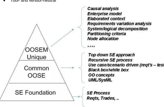
4.1 INCOSE Object-Oriented Systems Engineering Method (OOSEM)
Integrates top-down (functional decomposition) approach with model-based approach Leverages object-oriented concepts
o Uses OMG SysML (formerly UML) to support specification, analysis, design
and verification of systems
Intended to ease integration w/object-oriented S/W development, H/W development, and test
OOSEM includes the following activities:
o Analyze Stakeholder Needs
o Define System Requirements
o Define Logical Architecture
o Synthesize Candidate Allocated Architectures
o Optimize and Evaluate Alternatives
Model Based Systems Engineering (MBSE) Media Study
Tool- and vendor-neutral
Figure 4-1: OOSEM Pyramid - Top-Down (Functional Decomposition) Approach
Figure 4-2: OOSEM Activities - Integration W/Object-Oriented S/W Development, H/W Development, And Test
Model Based Systems Engineering (MBSE) Media Study
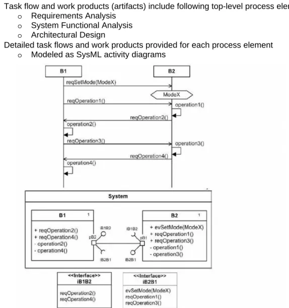
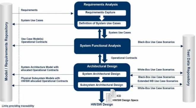
4.2 IBM Rational Telelogic Harmony-SE
Service Request-Driven Approacho Described by means of SysML structure diagrams
o State/mode changes (activities ) described as operational contracts
Somewhat mirrors “Vee” model
Task flow and work products (artifacts) include following top-level process elements:
o Requirements Analysis
o System Functional Analysis
o Architectural Design
Detailed task flows and work products provided for each process element
o Modeled as SysML activity diagrams
Model Based Systems Engineering (MBSE) Media Study
Figure 4-4: IBM Rational Telelogic Harmony-SE Process
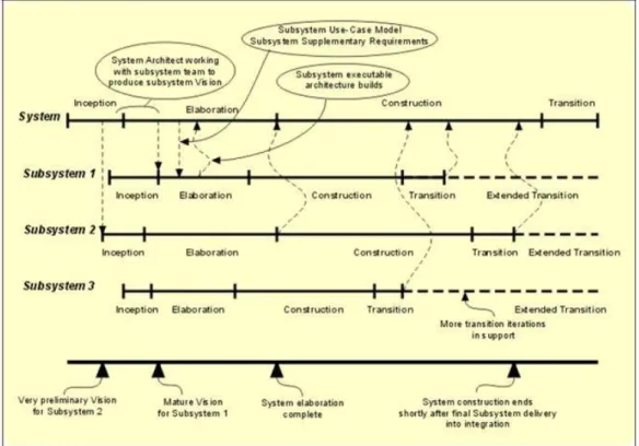
4.3 IBM Rational Unified Process for Systems Engineering (RUP-SE)
Extends RUP style of concurrent design and iterative development to support SE in Model-Driven Systems Development (MDSD)
o New roles, e.g., systems engineers
o New artifacts & disciplines, e.g., security, training, logistics
Emphasis on business modeling, business actors and flow of events to adequately define system requirements
Viewpoints for SE, i.e., model levels and model viewpoints
Introduces concept of locality — Member of system partition representing generalized or abstract view of physical resources; linked by connections (M. Cantor)
Scalability enhancements where each subsystem coupled w/locality has own derived requirements
o Allocated vs. derived requirements — locality/subsystem is allocated if fulfilling
system requirement; is derived if identified by studying how collaborates with other to meet system requirement
o Subsystem-level flowdown activity via use-case flowdown activity and flow of
events in “white-box view of system
Model Based Systems Engineering (MBSE) Media Study
Figure 4-5: RUP-SE - Viewpoint of SE Lifecycle
Model Based Systems Engineering (MBSE) Media Study
4.4 JPL State Analysis (SA)
JPL-developed methodology that leverages model- and state-based control architecture
o state - representation of momentary condition of evolving system o models - describe how state evolves
o state variables - abstractions representing “knowledge” of state
Known state of system is value of its state variables at time of interest
Together, state and models supply what is needed to operate system, predict future state, control toward desired state, & assess performance
SA methodology defines iterative process for state discovery & modeling
o Allows models to evolve as appropriate across project lifecycle
o SA requirements process helps bridge gap between requirements on software
specified by systems engineers
Mission Data System (MDS) — embedded software architecture designed to provide multi-mission information and control architecture for robotic exploration spacecraft
o SA information compiled in “State Database”
Model Based Systems Engineering (MBSE) Media Study
Figure 4-8: Elements and Relationships of State Analysis Synthesized with Functional Analysis
4.5 Vitech Model-Based Systems Engineering (MBSE) Methodology
Four (4) primary concurrent SE activities linked and maintained through commonsystem design repository
Each activity linked within context of associated “domains”
o Process Domain (SE activities)
o Source Requirements Domain
o Behavior Domain
o V&V Domain
o Architecture Domain
Strong adherence to agreed upon System Definition Language (SDL), i.e., SE schema or ontology to manage syntax and semantics of model artifacts
Uses incremental process known as “Onion Model”
o Allows complete interim solutions at increasing levels of detail during system
specification process
o Lower risk design approach by checking for completeness and discovering
constraints early in design process
Model Based Systems Engineering (MBSE) Media Study
Figure 4-9: Vitech MBSE Domains
Model Based Systems Engineering (MBSE) Media Study
4.6 Dori Object-Process Methodology (OPM)
Formal paradigm to systems development, lifecycle support, and evolution
o Combines simple OPDs (diagrams) with OPL (constrained natural language)
o Basic building blocks:
object - thing that exists or has potential of existence, physically or mentally,
process - pattern of transformation that object undergoes,
state - situation object can be at
[Reflective] methodology refers to system lifecycle as system evolution
o In OPM, “process” is a reserved word; therefore, “system process” is used
o System Developing process (SD1) contains three main stages, each can be
“zoomed” of which can be further zoomed
Requirement Specifying
Analyzing & Developing
Implementing
[also, Using & Implementing stage]
Visual models tool- and vendor-specific (see Tool Support below)
Model Based Systems Engineering (MBSE) Media Study
Figure 4-12: OPM Zooming into System Developing
4.7 Weilkiens
Systems
Modeling Process (SYSMOD)
The process is introduced in the book Systems Engineering with SysML/UML by Tim
Weilkiens. Tim Weilkiens, managing director of the German consulting company oose GmbH, is a member of the OMG working groups about SysML and UML and has written sections of the SysML specification. He is involved in the INCOSE MBSE activities and co-founder of the MBSE Challenge Team SE^2 Telescope Modeling.
(http://model-based-systems-engineering.com/)
The Systems Modeling Process (SYSMOD) is a pragmatic approach to model the
requirements and the functional and physical architecture of a system. It provides a toolbox of tasks with input and output work products, guidelines and best practices. SYSMOD uses the OMG Systems Modeling Language (OMG SysML).
User-oriented approach for requirements engineering and system architectures Allows different levels of modeling intensities
Guidelines and examples provided for each process activity SYSMOD Includes the following activities:
o Identify stakeholder
o Elicit requirements
o Define system context
o Analyze requirements, e.g. with use cases
o Define domain model
o Define system architecture on different levels (functional, logical, physical)
Provides additional activities, e.g., for functional architectures or variant modeling Tool vendor independent methodology
Model Based Systems Engineering (MBSE) Media Study
Figure 4-13: Weilkiens Systems Modeling Process (SYSMOD) Methodology
4.8 Fernandez ISE & Process Pipelines in OO Architectures (ISE&PPOOA)
ISE&PPOOA (Integrated Systems Engineering and PPOOA) provides an integratedprocess, methods and a tool for systems engineering of software intensive mechatronic systems.
The ISE part of the process includes the first steps of a systems engineering process applicable to any kind of system, not only the software intensive ones. The ISE subprocess integrates traditional systems engineering best practices and MBSE. The PPOOA part of the process emphasizes the modeling of concurrency as earlier as
possible in the software engineering part of the integrated process.
The integration between the systems engineering subprocess and the PPOOA
software engineering subprocess is achieved by using a responsibility driven software analysis approach supported by CRC cards, a technique proposed in the OOPSLA´89 by Beck and Cuningham.
ISE&PPOOA provides a collection of guidelines or heuristics to help the engineers in the architecting of a system.
One of the project deliverables is the functional architecture representing the functional hierarchy using the SysML block definition diagram. This diagram is complemented with activity diagrams for the main system functional flows. The N2 diagram is used as an interface diagram where the main functional interfaces are identified. A textual description of the system functions is also provided as part of the deliverable. Other of the deliverables is the physical architecture, representing the system
decomposition into subsystems and parts using the SysML block definition diagram. This diagram is complemented with SysML internal block diagrams for each
subsystem and activity and state diagrams as needed. A textual description of the system blocks is also provided. The heuristics used for the particular architecture solution are identified and documented.
The software subsystem architecture is described in PPOOA using two views supported by one or more diagrams using UML notation. One view is the static of structural view and the other is the dynamic or behavioral view of the system. The system architecture diagram represents the system components and the composition and usage relations between them. Coordination mechanisms used as connectors are also represented. The system behavioral view is supported by UML/SysML activity
Model Based Systems Engineering (MBSE) Media Study
diagrams representing an internal view of the flow of actions performed by the system in response to an event
Bidirectional functional allocation between components and system responses modeled as activity diagrams is considered and tool supported
ISE&PPOOA makes easy the architecture evaluation from time responsiveness characteristics
Figure 4-14: Fernandez ISE & Process Pipelines in OO Architectures (ISE&PPOOA) Methodology
Model Based Systems Engineering (MBSE) Media Study
5.0 MBSE Modeling Language Standards
(Source data:http://www.incose.org/productspubs/pdf/techdata/mttc/mbse_methodology_survey_2008-0610_revb-jae2.pdf)
Unified Modeling Language™, UML®, and Systems Modeling Language™, OMG SysML™,
(both covered it more details below) are visual modeling language standards managed under the auspices of the Object Management Group™, OMG™; an open membership, not-for-profit consortium that produces and maintains computer industry specifications for interoperable enterprise applications.
UML and OMG SysML are intended to be complementary. SysML was developed in
partnership between the OMG and INCOSE and is based on the UML, specifically, UML 2.0 (see Figure 5-1) SysML provides an additional set of modeling diagrams to model complex systems that include hardware, software, data, procedures and other system components. Together, UML and SysML go a long way to help unify what has historically been a
communication chasm between the systems and software engineering communities.
5.1 OMG
SysML
TM(Source data: http://www.omgsysml.org/)
The OMG Systems Modeling Language (OMG SysML™) is a general-purpose graphical modeling language for specifying, analyzing, designing, and verifying complex systems that may include hardware, software, information, personnel, procedures, and facilities. In particular, the language provides graphical representations with a semantic foundation for modeling system requirements, behavior, structure, and parametrics, which is used to integrate with other engineering analysis models. SysML represents a subset of UML 2 with extensions needed to satisfy the requirements of the UML™ for Systems Engineering RFP as indicated in Figure 5-1. SysML leverages the OMG XML Metadata Interchange (XMI®) to exchange modeling data between tools, and is also intended to be compatible with the evolving ISO 10303-233 systems engineering data interchange standard.
Figure 5-1: Relationship Between SysML and UML
The SysML diagram types are identified in Figure 5-2 for a more detailed description refers to the OMG SysML Tutorial for an overview of the language or the APL MBSE with SysML course material.
Model Based Systems Engineering (MBSE) Media Study
Figure 5-2: SysML Diagram Types
Figure 5-3 shows an example of the 4 pillars of the OMG systems Modeling Language (OMG SysML™).
Model Based Systems Engineering (MBSE) Media Study
Multiple vendors announced SysML implementations:
Atego (previously) ARTiSAN Software Tools
CoFluent Design
IBM
o Rhapsody
o Tau
InterCAX
No Magic MagicDraw SysML
Papyrus for SysML (open source eclipse modeling tool)
SOFTEAM MODELIOSOFT - Solutions for System Architects
Software Stencils - Microsoft Visio SysML and UML templates
Sparx Systems
5.2 UML
(Source Data: http://www.uml.org/ and
http://en.wikipedia.org/wiki/Unified_Modeling_Language)
The Unified Modeling Language™ - UML - is OMG's most-used specification, and the way the world models not only application structure, behavior, and architecture, but also business process and data structure.
UML includes a set of graphic notation techniques to create visual models of object-oriented software-intensive systems.
UML is used to specify, visualize, modify, construct and document the artifacts of an object-oriented software-intensive system under development.[2] UML offers a standard way to visualize a system's architectural blueprints, including elements such as:
activities actors
business processes
database schemas
(logical) components
programming language statements
reusable software components
UML combines techniques from data modeling (entity relationship diagrams), business modeling (work flows), object modeling, and component modeling. It can be used with all processes, throughout the software development life cycle, and across different
implementation technologies. UML has synthesized the notations of the Booch method, the Object-modeling technique (OMT) and Object-oriented software engineering (OOSE) by fusing them into a single, common and widely usable modeling language.
UML models may be automatically transformed to other representations (e.g. Java) by means of QVT-like transformation languages. UML is extensible, with two mechanisms for
Model Based Systems Engineering (MBSE) Media Study
6.0 MBSE Software Tools
The following tools have been captured and top level information each tool has been provided below:
SAE Architecture Analysis & Design Language (AADL)
Vitech CORE
MagicDraw®
Phoenix Integration
ModelCenter
IBM® Rational® Rhapsody® Eclipse
Isight & SIMULIA
6.1 MBSE Tools and Relevance of other “de-facto” MBSE visual modeling
standards
(Source data: INCOSE Survey of MBSE Methodologies, INCOSE-TD-2007-003-02, 5/23/2008
http://www.incose.org/productspubs/pdf/techdata/mttc/mbse_methodology_survey_2008-0610_revb-jae2.pdf)
A recommendation for the MBSE tool vendors that currently do not support UML and/or OMG SysML is to add this capability to the product roadmap as soon as possible; particularly, SysML. The advantage of using industry standard visual modeling languages over vendor-specific modeling languages is clear and does not warrant debate. Some MBSE tools, for example, only support the Enhanced Function Flow Block Diagram (EFFBD) visual modeling capability, which in some cases (e.g., Vitech CORE/COREsim) support executable modeling constructs that allows the systems engineer to run discrete-event simulations based on EFFBD models. This is a very powerful capability and there is no technical reason that such an executable capability could not be added to OMG SysML diagrams such as activity diagrams and state diagrams. Bock has documented how both UML (UML 2 specifically) and SysML can be used for activity modeling and how these standards can extended to fully support EFFBDs.
6.2 SAE Architecture Analysis & Design Language (AADL)
(Source data: http://www.aadl.info/aadl/currentsite/)
This standard defines a language for describing both the software architecture and the execution platform architectures of performance-critical, embedded, real-time systems; the language is known as the SAE Architecture Analysis & Design Language (AADL). AADL has the following features:
Gives you the power to specify and generate a single model that can be analyzed for multiple qualities.
Provides an industry-standard, textual and graphic notation with precise semantics to model applications and execution platforms
Features an XML interchange format that supports the exchange of models between subcontractors, integrators, and agencies
Includes a UML profile that presents AADL as a specialized modeling notation within UML framework
Supported by commercial and open source tool solutions—including the SEI Open Source AADL Tool Environment (OSATE)
Model Based Systems Engineering (MBSE) Media Study
An AADL model describes a system as a hierarchy of components with their interfaces and their interconnections. Properties are associated to these constructions. AADL components fall into two major categories: those that represent the physical hardware and those
representing the application software. The former is typified by processors, buses, memory, and devices, the latter by application software functions, data, threads, and processes. The model describes how these components interact and are integrated to form complete systems. It describes both functional interfaces and aspects critical for performance of individual components and assemblies of components. The changes to the runtime architecture are modeled as operational modes and mode transitions.
6.3 Vitech CORE
(Source data http://www.vitechcorp.com/products/core.shtml)
CORE® is a comprehensive modeling environment built for complex systems engineering problems. Whether you are performing a one-month study or a long-term architecture design, project success depends on getting started quickly, finding the right solution, and being responsive to program changes. Leveraging CORE’s deep model-centric capability delivered through a rich, intuitive user framework delivers early and continuous insight into your problem domain.
Leverage CORE’s integrated modeling capabilities to assess and control design and program risks. By linking all elements of your system through a central model, you’ll have greater visibility into drivers for risk and learn more quickly where the weaknesses are in your design. Stay competitive by avoiding poor designs that are more expensive. Build better models and deliver better products to market through:
Integrated requirements management ensure that you capture customer needs accurately
Fully executable behavior models help you unlock elegant functionality
Architecture development tools guide you swiftly to subsystems and components Validation and Verification (simulation) highlights gaps and missing functions
Comprehensive system documentation ensures you deliver a complete solution with a clear message
CORE enables you to make the shift to MBSE quickly and easily by guiding you through a simple, layered approach to development. As new users join your team, you’ll be able to collaborate more easily and share a common
modeling language and to focus on the engineering work and not the tools.
Easy to use Parsers help you get information into the model quickly so you can build the solution correctly the first time. Reduce rework by verifying you’ve secured the right requirements early.
Simple Model Construction gives new users a flexible way to visualize the interactions between requirements, functions, and components so you can always keep your focus.
Model Based Systems Engineering (MBSE) Media Study
Figure 6-1: Simple Model Construction
Multiple Modeling Notations help you evaluate the system through a variety of integrated graphical views: hierarchies, functional flow and enhanced functional flows, N2, IDEF0, and physical block. Change one diagram and see the update reflected on all impacted views.
Automated Document Creation helps you generate formal documentation, including DoDAF 2.0 views, instantly from the system definition database.
Enhanced Communication: CORE gives you a powerful new medium to capture the intent of your system and effectively communicate across your team. You’ll be able to
demonstrate aspects of your design without sacrificing traceability. CORE gives you the power of a fully integrated data model with the simplicity of a graphical
environment.
Figure 6-2: Example of CORE Model Communication
6.4 MagicDraw
®(Source data https://www.magicdraw.com/what_is)
MagicDraw is an award-winning business process, architecture, software and system modeling tool with teamwork support. Designed for Business Analysts, Software Analysts, Programmers, QA Engineers, and Documentation Writers, this dynamic and versatile development tool facilitates analysis and design of Object Oriented (OO) systems and databases. It provides the industry's best code engineering mechanism (with full round-trip support for Java, C++, C#, CL (MSIL) and CORBA IDL programming languages), as well as database schema modeling, DDL generation and reverse engineering facilities.
Ten Reasons MagicDraw Literally Outpaces the Competition 1. Promotes quick learning with intuitive interface 2. Creates diagrams faster than any tool on the market 3. Derives models from existing source code in just seconds 4. Visualizes your model in a few quick steps
5. Keeps your team in the express lane by enabling them to work on the same model in parallel
6. Delivers source code from your UML model instantly
7. Eliminates tedious document preparation with automatic report generation! 8. Extends UML capabilities beyond UML 2 -- in a snap
Model Based Systems Engineering (MBSE) Media Study
9. Accelerates your 'travel time' between modeling domains 10. Enables speedy navigation through your models
6.4.1 Related MagicDraw Products and Plugins
MagicDraw has several add-ons to enhance the use of MagicDraw’s capability. The following is the list from the MagicDraw website. Follow the hyperlink for detailed information about
each of the add-ons. https://www.magicdraw.com/magicdraw_addons
Teamwork Server
Cameo XSD Import Import Plugin Nomos OCL Business Rules
Testing Addon
UPDM Plugin
SysML Plugin
Cameo Simulation Toolkit Cameo Business Modeler
Cameo DataHub
Cameo Workbench
Cameo SOA+
Cameo Data Modeler
TOGAF Plugin QVT Plugin Merge Plugin CameoMDA Plugin MagicRQ Plugin Cameo Inter-Op RSXConverter RConverter ParaMagic Plugin
Methodology Wizards Plugin
SPEM Plugin
MARTE Profile
MagicDraw Reader on iPhone
DoDAF Plugin
CSV Import Plugin
6.5 Phoenix
Integration
(Source data: http://www.phoenix-int.com/)
Phoenix Integration, a global leader in software integration and Multidisciplinary Design Optimization (MDO), see Figure 6-3: Delivers Multidisciplinary Design Optimization (MDO), provides process integration and design optimization software that empowers you to improve your decision-making and analysis management capabilities. Our software delivers MDO and simplifies System-of-Systems analysis, see Figure 6-4: Simplifies System-of-Systems (SoS) Analysis.
Model Based Systems Engineering (MBSE) Media Study
Figure 6-4: Simplifies System-of-Systems (SoS) Analysis
6.5.1 Design Space Navigation/Optimization & Variable Sensitivity Analysis
Multidisciplinary design and analysis plays a vital role in the Phoenix solution. Once the components of your process are integrated, you can employ various design exploration tools to create an optimized design, run what-if trade studies or further inspect the design space to find the weaknesses in your Model.Design Space Navigation/Optimization
Change parameters, goals, and constraints on-the-fly
Locate best designs for specified parameters, goals and constraints View Pareto Optimal designs
Visually follow progress of optimization algorithms Visually guide search algorithm within design space Generate design comparison reports
Variable Sensitivity Analysis
Visualize key global variable sensitivities-main effects and interaction effects-to focus on most influential variables
Visualize local variable sensitivities
Drag control panel's interactive sliders to easily and visually navigate design space in real time
View key relationships and trends using advanced plotting options including glyph, star glyph, parallel coordinates, scatter, scatter matrix, histogram, and 2D histogram
6.5.2 ModelCenter
(Source data: http://www.phoenix-int.com/software/phx_modelcenter_10.php)
ModelCenter® 10.0 by Phoenix Integration is a graphical environment for automation, integration, and design optimization that supports your entire product development team. It allows you to lower cost and reduce product development time. With PHX ModelCenter, you can quickly create an engineering process and then explore the design space to find the best design. PHX ModelCenter is adaptable, and works well with groups whose design processes change frequently.
Model Based Systems Engineering (MBSE) Media Study
The engineering process is inherently about making design decisions and tradeoffs between competing objectives. There are often too many choices and too little time to evaluate them all. Computer simulation has helped the process by allowing engineers and analysts to create “virtual” prototypes. Even with simulation, however, design is largely an intuition based
guessing game to find good designs. Furthermore, design decisions increasingly have cross-discipline impacts that are not understood by any one expert thus limiting the effectiveness of commonly used experience based approaches.
PHX ModelCenter® enables engineers to automate and integrate design codes and build complex parametric models of systems. When performing trade studies with these models, users sometimes face having to navigate large, complex design spaces using basic plotting tools. Searching for the best designs with optimization algorithms and communicating and justifying results to management less familiar with design optimization technology can be a difficult task. Includes:
Variable Influence Profiler (VIP) Prediction Profiler (PP)
Data Visualizer
6.5.2.1 Benefits
Better Designs - PHX ModelCenter gives you powerful tools to inspect designs and find weaknesses. Correcting these weaknesses early in the design process can save corporations millions. Trade studies within PHX ModelCenter help you and your team find optimal solutions with lower weight, higher performance, and more robustness in the design.
Reduces Errors - Manual data translation and linking is costly and error-prone. Automating this step in the design process helps reduce mistakes.
Saves Time - PHX ModelCenter eliminates the manual transfer of data between applications, thereby reducing design cycle time. With that "extra" time, you can evaluate more design alternatives which results in a better final product.
Cohesive Team Environment - Your team of engineers can use PHX ModelCenter to coordinate data and share design applications over a network of computers. Design data that used to be sent via fax, email, or ftp can now be linked automatically through PHX ModelCenter.
Easy to Deploy - PHX ModelCenter integrates seamlessly with existing applications used by your entire team.
6.6 IBM® Rational® Rhapsody®
(Source data: http://www-01.ibm.com/software/awdtools/rhapsody/)
IBM® Rational® Rhapsody® family provides collaborative design and development for systems engineers and software developers creating real-time or embedded systems and software. Rational Rhapsody helps diverse teams collaborate to understand and elaborate requirements, abstract complexity visually using industry standard languages (UML, SysML, AUTOSAR, DoDAF, MODAF, UPDM), validate functionality early in development, and automate delivery of innovative, high quality products.
Rational Rhapsody Designer for Systems Engineers enables a Model Based Systems Engineering (MBSE) approach with SysML for visualization of complex requirements and model execution for early validation of requirements, architectural trade off analysis and mitigation of project risks.
Model Based Systems Engineering (MBSE) Media Study
Integrated requirements and modeling environment using industry standard SysML or UML diagrams
Dynamically analyze and execute SysML parametric diagrams to assist in trade study analysis
Simulation executes the model to help validate architecture and behavior including activity diagram execution using token passing semantics
Full lifecycle traceability and analysis from requirements to design Static model checking analysis helps improve design consistency Automates tedious tasks with systems engineering toolkit
Capture systems of systems with additional DoDAF, MODAF and UPDM Add On Includes configuration management interface support with advanced graphical
difference and merging capabilities for parallel development
Automate documentation across product lifecycle with Rational Publishing Engine integration
Collaborative development with integration with the Jazz- based IBM® Rational® Team Concert solution through Eclipse
Automate validation testing with Rational Rhapsody TestConductor Add On including Rational Quality Manager integration
IBM® Rational® Rose® import for legacy system re-use
Integrations with IBM Rational products such as IBM Rational DOORS, IBM Rational Systems Architect, IBM Rational ClearCase for full product lifecycle development Rational Rhapsody Designer for Systems Engineers 7.6.1 provides a client to share
and review The Mathworks Simulink designs through the integration with Rational Rhapsody
6.7 Eclipse
Open source tool.(Source data: http://www.eclipse.org/org/ and http://www.eclipse.org/modeling/mdt/papyrus/)
6.7.1 What is Eclipse and the Eclipse Foundation?
Eclipse is an open source community, whose projects are focused on building an open development platform comprised of extensible frameworks, tools and runtimes for building, deploying and managing software across the lifecycle. The Eclipse Foundation is a not-for-profit, member supported corporation that hosts the Eclipse projects and helps cultivate both an open source community and an ecosystem of complementary products and services. The Eclipse Project was originally created by IBM in November 2001 and supported by a consortium of software vendors. The Eclipse Foundation was created in January 2004 as an independent not-for-profit corporation to act as the steward of the Eclipse community. The independent not-for-profit corporation was created to allow a vendor neutral and open, transparent community to be established around Eclipse. Today, the Eclipse community consists of individuals and organizations from a cross section of the software industry. In general, the Eclipse Foundation provides four services to the Eclipse community: 1) IT Infrastructure, 2) IP Management,3) Development Process, and 4) Ecosystem Development. Full-time staff are associated with each of these areas and work with the greater Eclipse community to assist in meeting the needs of the stakeholders.
Model Based Systems Engineering (MBSE) Media Study
6.7.2 A Unique Model for Open Source Development
The Eclipse Foundation has been established to serve the Eclipse open source projects and the Eclipse community. As an independent not-for-profit corporation, the Foundation and the Eclipse governance model ensures no single entity is able to control the strategy, policies or operations of the Eclipse community.
The Foundation is focused on creating an environment for successful open source projects and to promote the adoption of Eclipse technology in commercial and open source solutions. Through services like IP Due Diligence, annual release trains, development community support and ecosystem development, the Eclipse model of open source development is a unique and proven model for open source development.
6.7.3 About
Papyrus
Papyrus is aiming at providing an integrated and user-consumable environment for editing any kind of EMF model and particularly supporting UML and related modeling languages such as SysML and MARTE. Papyrus provides diagram editors for EMF-based modeling languages amongst them UML 2 and SysML and the glue required for integrating these editors (GMF-based or not) with other MBD and MDSD tools.
Papyrus also offers a very advanced support of UML profiles that enables users to define editors for DSLs based on the UML 2 standard. The main feature of Papyrus regarding this latter point is a set of very powerful customization mechanisms which can be leveraged to create user-defined Papyrus perspectives and give it the same look and feel as a "pure" DSL editor.
6.8 Isight & the SIMULIA Execution Engine
(Source data:
http://www.3ds.com/products/simulia/portfolio/isight-simulia-execution-engine/overview/)
SIMULIA and Isight are produced by Dassault Systèmes
The tool information on Isight and SIMULIA doesn’t specifically call out MBSE but their goal is to integration information across system engineering work products and models.
6.8.1 Dassault
Systèmes Company Information
Dassault Systèmes, the 3D Experience Company, provides business and people with virtual universes to imagine sustainable innovations. Its world-leading 3D design software, 3D Digital Mock-Up and Product Lifecycle Management (PLM) solutions transform the way products are designed, produced, and supported.
(http://www.3ds.com/company/about-dassault-systemes/our-vision/)
6.8.2 SIMULIA
Overview
SIMULIA enables collaboration on performing virtual tests and meeting performance requirements. Its portfolio provides powerful tools that enable fast, accurate performance studies on parts, assemblies, components, and products designed with V6. It also enables organizations to capture their simulation knowledge, deploy approved methods, manage applications, and share simulation results to enable collaboration and accurate performance-based decisions.
Model Based Systems Engineering (MBSE) Media Study
6.8.3 Isight & SEE Overview
In today’s complex product development and manufacturing environment, designers and engineers are using a wide range of software tools to design and simulate their products. Often, chained simulation process flows are required in which the parameters and results from one software package are needed as inputs to another package and the manual process of entering the required data can reduce efficiency, slow product development, and introduce errors in modeling and simulation assumptions.
SIMULIA provides market-leading solutions that improve the process of leveraging the power of various software packages. Isight and the SIMULIA Execution Engine (formerly Fiper) are used to combine multiple cross-disciplinary models and applications together in a simulation process flow, automate their execution across distributed compute resources, explore the resulting design space, and identify the optimal design parameters subject to required constraints.
Our proven simulation automation and optimization solutions enable engineering teams to: Drastically reduce design cycle time through integrating workflow processes in an
automated environment
Deliver more reliable, better-quality products through accelerated evaluation of design alternatives
Lower hardware investments through effective use of legacy systems and more efficient job distribution
Eliminate the bottlenecks of ineffective communication by enabling secure design collaboration among partners
Model Based Systems Engineering (MBSE) Media Study
7.0 Companies working to implement MBSE
This section is not intended to list ALL companies working to implement MBSE but it is to highlight a few who have recently made presentations or released papers available for open use.
The following companies presented at the Model-based Systems Engineering (MBSE) Workshop held on January 21-22, 2012 at the INCOSE International Workshop (IW) in Jacksonville, Florida.
The presentations from each of the companies covered the multi-disciplinary engineering modeling approaches, key practices, and integration challenges of MBSE.
7.1 Lockheed
Martin
Digital Tapestry, presented by Chris Oster Link to presentation:
http://www.omgwiki.org/MBSE/lib/exe/fetch.php?media=mbse:mbse_iw_2012-lm_digital_tapestry-oster.pptx
System Modeling, presented by John Watson Link to Presentation:
http://www.omgwiki.org/MBSE/lib/exe/fetch.php?media=mbse:mbse_iw_2012-sys_modeling_and_req_flowdown_watson_r5.pptx
7.2 Deere & Co
Transition to Model Based Embedded System Development, presented by Jim Ross Link to presentation:
http://www.omgwiki.org/MBSE/lib/exe/fetch.php?media=mbse:mbse_iw_2012-transition_to_model_based_embedded_system_development-ross.pptx
7.3 Rockwell
Collins
Model-based Manufacturing Modeling, presented by Greg Pollari Link to presentation:
http://www.omgwiki.org/MBSE/lib/exe/fetch.php?media=mbse:mbse_iw_2012-manufacturing_modeling_with_sysml-pollari-reva.pptx
7.4 Raytheon
Cost/Logistics Modeling, presented by Chris Adams Link to presentation:
http://www.omgwiki.org/MBSE/lib/exe/fetch.php?media=mbse:mbse_iw_2012-cost_logistics_modeling_revb-adams.ppt
7.5 ATA
Engr
Multi-Disciplinary Mechanical Modeling, Management and Exchange, presented by Dr. Clark Briggs
Link to presentation:
http://www.omgwiki.org/MBSE/lib/exe/fetch.php?media=mbse:mbseiw2012-multidisciplinary_modeling-briggs-b.pptx