USER GUIDE
Hardware Development Kit
Hardware Development Kit
The Atmel® Hardware Development Kit (HDK) provides all necessary
information for a developer to make hardware that is compatible with Atmel Xplained Pro products, integrate it with Atmel Studio as an extension and add example firmware to Atmel Software Framework (ASF).
Table of Contents
Hardware Development Kit ... 1
1. Introduction ... 3
1.1. Compatible Xplained Pro hardware ... 3
1.2. Studio integration ... 3
1.3. Example code ... 4
2. How to Design a Xplained Pro Extension ... 5
2.1. Xplained Pro ID system ... 5
2.1.1. Overview ... 5
2.1.2. ID system implementation on extensions ... 5
2.1.3. ID device data ... 6
2.1.4. Data encoding ... 6
2.1.5. Creating your own ID data ... 7
2.1.6. Programming the ID device ... 7
2.2. Xplained Pro extension naming convention ... 8
2.2.1. Product name ... 8
2.2.2. Silkscreen text ... 8
2.3. Xplained Pro connectors ... 9
2.3.1. Xplained Pro extension header ... 9
2.3.2. Xplained Pro power header ... 10
2.3.3. Xplained Pro segment LCD extension connector ... 10
2.3.4. Xplained Pro LCD connector ... 11
2.4. Power specifications ... 12
2.5. Extension board templates ... 13
2.5.1. Designing a board with the standard extension connector ... 13
2.5.2. Designing a board with the segment LCD connector ... 25
2.5.3. Designing a board with the LCD connector ... 26
3. How to Integrate a Xplained Pro Extension in Atmel
Studio ... 27
3.1. Xplained Pro Landing Page ... 27
4. How to Integrate Code Examples for a Xplained Pro
Extension in Atmel Studio ... 28
A. Appendix ... 29
A.1. Document Revision History ... 29
A.2. xpro_id Version History ... 29
1.
Introduction
The Hardware Development Kit (HDK) describes how to integrate a Xplained Pro hardware design seamlessly into the Atmel tools and software offering. Three requirements must be fulfilled in order to accomplish this task and these are:
1. Compatible hardware 2. Atmel Studio integration 3. Example code
When all these requirements are fulfilled a good user experience is achieved because each step in the evaluation process is covered and the user has easy access to everything he needs.
1.1
Compatible Xplained Pro hardware
Xplained Pro is an evaluation platform that provides the full Atmel microcontroller experience. The platform consists of a series of Microcontroller (MCU) boards and extension boards that are integrated with Atmel Studio, have Atmel Software Framework (ASF) drivers and demo code, support data streaming and more. Xplained Pro MCU boards support a wide range of Xplained Pro extension boards that are connected through a set of standardized headers and connectors. Each extension board has an identification (ID) chip to uniquely identify which boards are mounted on a Xplained Pro MCU board.
All Xplained Pro MCU borads feature an Atmel Embedded Debugger (EDBG). The EDBG supports
programming and debugging of the target MCU on the Xplained Pro MCU board and works as a gateway for a hardware identification system that lets Atmel Studio detect connected hardware. The hardware identification system covers identification of Xplained Pro MCU boards and identification of connected extension board. This document has the information required to implement a Xplained Pro extension board with the hardware identification system.
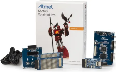
Figure 1-1. Typical Xplained Pro kit overview
1.2
Studio integration
When Atmel Studio detects Xplained Pro compatible hardware it will search for a landing page for it and present it to the user. The landing page contains:
● Short description of the kit
● Picture of the kit
● Links to kit documentation
● Link that opens a list with relevant applications for this kit (filtered ASF examples list)
● Link to Atmel store or other places where the kit can be bought
Other information on the landing page is obtained directly from the connected hardware via the kit identification system e.g. revision, capabilities, serial number etc.
If no landing page is found the user will be requested to update the Atmel kits extension or to check for required additional extensions in the Atmel gallery.
1.3
Example code
The final step of the integration is addition of example code for the hardware and this is described in detail in the Software Development Kit (SDK).
2.
How to Design a Xplained Pro Extension
2.1
Xplained Pro ID system
Identification of extension boards for the Xplained Pro platform is required in order to leverage the ease of use for Atmel products. The intention of the identification is not to protect the hardware from being copied.
Identified expansion boards are reported via the Embedded Debugger to the host PC software, which is Atmel Studio. Based on the detected hardware Atmel Studio will then provide additional information to the user such as:
● Link to user guides and relevant datasheets
● Available Atmel Software Framework (ASF) applications for the extension
● Extension revision and features
This chapter is important for all developers that want to implement the ID system in a design e.g. on extensions for Xplained Pro.
2.1.1 Overview
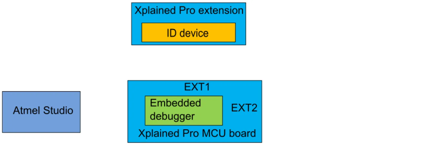
The Embedded Debugger (EDBG) is the central part in the overall system because it serves as a gateway between the hardware and the host PC software. The system block diagram in Figure 2-1, “ID system
overview” shows how the main components of the system and how they connect to each other. Each extension connector on a Xplained MCU board has a unique ID channel which is connected to the EDBG and to an ID device on a connected extension board. Upon power up the EDBG will check all ID channels for ID devices, read out the product information and store this internally. Once a connection to the host PC software is established this information can be retrieved and presented to the user.
Figure 2-1. ID system overview
Atmel Studio
Xplained Pro extension
ID device
Xplained Pro MCU board
EXT1
EXT2
Embedded
debugger
Xplained Pro extension
ID device
2.1.2 ID system implementation on extensions
The ID device that must be mounted on Xplained Pro extensions is the Atmel ATSHA204 in a single-wire configuration where the device is powered through the communication line. On the Atmel Xplained Pro extensions the device with the ordering code ATSHA204-TSU-T is used. Relevant features of the device are:
● Operation voltage from 2.0V to 5.5V
● Single wire interface
● 3-lead SOT23 (one wire)
● Data area with 512 bytes
● Configuration area with 88 bytes
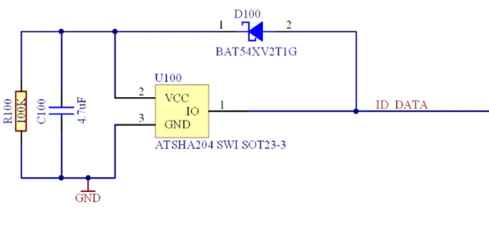
The example in Figure 2-2, “ID device circuitry” shows the implemented ID circuitry on the Xplained Pro extension boards. The ID_DATA signal is routed to the Embedded Debugger where this signal is pulled-up. The ID chip is powered through the ID_DATA line via D100. R100 acts as a bleeding resistor to discharge
C100 when the extension is unplugged, this is necessary in order to get the ID device in a safe state within a reasonable time before the board is plugged in again. The ID_DATA line is connected to a dedicated pin on the extension header your Xplained Pro board implements.
Figure 2-2. ID device circuitry
2.1.3 ID device data
The following data must be programmed into the ID device so that the most vital information can be presented to the user in Atmel Studio.
1. Manufacturer name 2. Product name 3. Product revision 4. Product serial number
5. Minimum supported voltage for the extension board 6. Maximum supported voltage for the extension board
7. Minimum current that is required to support the extension board
The product name is the key for a lookup in the available kits list in Studio and it is therefore vital that this information is unique and always present. Additional differentiation e.g. based on the manufacturer name is possible but currently not implemented. If a kit name cannot be resolved in Studio it will be suggested to the user that he should update or install the required extension and he can do this based on the available information that is read out from the ID device.
This data is placed in the OTP zone which means once it is programmed into the ID device memory it can’t be erased.
2.1.4 Data encoding
The data in the ATSHA204 is encoded in the following way. Manufacturer name, product name, product revision and serial number are stored as 0 terminated ASCII strings. This allows all the strings to have variable length. Minimum voltage, maximum voltage and required current are stored as unsigned 16 bit integer values at the last 6 bytes of the OTP memory zone. The byte ordering is big endian.
It is required to know the entire content of the OTP zone before locking it. All unused bytes in the OTP memory have to be written to a known value. All unused area of the OTP memory, meaning all bytes between the last ASCII string (terminated with the ‘\0’ character) and the 6 bytes for the max/min values is filled with 0xFF. These bytes are marked as DUMMY BYTES in the example table below.
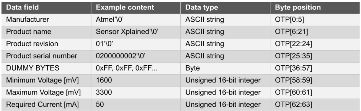
It is also required to know the entire content of the data memory prior to locking the OTP zone, thus the entire data memory is filled with 0x00. The data zones are not locked for writing so it is possible, if desirable, to write updated information about the kit in the data memory. The table below shows an example of a preprogrammed memory for a fictional extension board called "Sensor Xplained".
Table 2-1. Exampled content for the ID device
Data field Example content Data type Byte position
Manufacturer Atmel’\0’ ASCII string OTP[0:5]
Product name Sensor Xplained’\0’ ASCII string OTP[6:21]
Product revision 01’\0’ ASCII string OTP[22:24]
Product serial number 0200000002’\0’ ASCII string OTP[25:35]
DUMMY BYTES 0xFF, 0xFF, 0xFF... Byte OTP[36:57]
Minimum Voltage [mV] 1600 Unsigned 16-bit integer OTP[58:59]
Maximum Voltage [mV] 3300 Unsigned 16-bit integer OTP[60:61]
Required Current [mA] 50 Unsigned 16-bit integer OTP[62:63]
Note All ASCII strings are terminated with the value 0x00 (‘\0’)
Note 4 bytes are used for string terminations (‘\0’), 6 bytes are used for max/min values storage. That leaves 54 bytes for ASCII characters. This means that the combination of manufacturer, product name, revision and serial number cannot exceed 54 characters.
Note The Minimum and Maximum voltage parameters may be used if the Xplained Pro boards get variable target voltage and switching of power (VCC) to the Extension ports. The Extension kit's voltage range can be read from the ID chip without applying power to the Extension module, and power can be switched on if target voltage is within the valid voltage range of the Extension module.
2.1.5 Creating your own ID data
All extensions must have a unique product name and manufacturer so that they can be associated with
available documentation and firmware in Atmel Studio in the future. This means all products must be registered so that the uniqueness of the name is ensured. To register an Xplained Pro extension module id send an e-mail to [email protected] with the manufacturer name and product name.
2.1.6 Programming the ID device
The ID device can be programmed via the Embedded Debugger that is mounted on the Xplained Pro MCU boards. That means all Xplained Pro MCU boards can act as a programmer for the ID device by connecting one of the ID signals.
Atmel provides a Python2 module for reading and programming ID devices called xpro_id. The module is tested with pyton 2.7.43. The latest installer for the xpro_id package can be downloaded from the Atmel Gallery developer page4.
The best way to read the documentation for the xpro_id Python module is to use pydoc.py to create a locally hosted web page. Running the following command5 in a command prompt will host the documentation at http:// localhost:1234/xpro_id.html.
C:\Python27\python.exe C:\Python27\Lib\pydoc.py -p 1234
1 mailto:[email protected] 2 http://www.python.org/
3The module should be compatible with other 2.x.x versions of Python as long as ctypes is installed. 4 http://gallery.atmel.com/Partner
The Python package is split in two classes; edbg_hid and xpro_id. edbg_hid interfaces cmsis_dap.dll to communicate with the embedded debugger and provides the required functions to read and program Xplained Pro ID devices. xpro_id provides an example of interfacing the edbg_hid class.
Note The xpro_id class is provided as an example on how to interface the edbg_hid class. The code may be altered to fit a specific manufacturing setup.
Tip Atmel uses a more direct interface to the edbg_hid class, with less checks and test on input data, in mass production of kits. Several of the input parameters are also stored in configuration files for each kit.
Questions or issues regarding Xplained Pro ID programming can be directed to [email protected]. Version changelog for the xpro_id module is listed in “xpro_id Version History” on page 29
2.2
Xplained Pro extension naming convention
2.2.1 Product name
All boards of the product family are named based on the following scheme: [device/technology] Xplained Pro
In addition it is possible to extend the name with a sub-part that is used to differentiate products within a product line.
● Sensors Xplained Pro Inertial
● Sensors Xplained Pro Pressure
● Security Xplained Pro Authentication
When several extensions exist with the same name and sub-naming, these can be distinguished by adding a number:
● Sensors Xplained Pro Inertial One
● OLED1 Xplained Pro
● IO1 Xplained Pro
2.2.2 Silkscreen text
The board name on the PCB itself is all in capital letters, where the X in XPLAINED is the double font size than the rest of the letters. The “PRO” is attached at the end with half the font size. For example 2mm height for standard text, 4mm height for the X and 1mm height for the “PRO”. The font size that was used is Verdana with a 0.5mm inverted border.
Figure 2-3. Extension silkscreen naming example 1
Figure 2-4. Extension silkscreen naming example 2
2.3
Xplained Pro connectors
2.3.1 Xplained Pro extension header
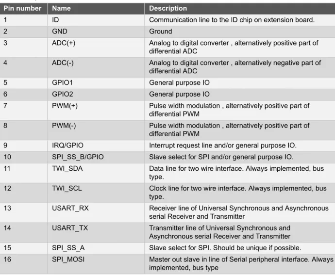
All Xplained Pro kits have one or more dual row, 20 pin, 100mil extension headers. Xplained Pro MCU boards have male headers while Xplained Pro extensions have their female counterparts. Note that all pins are not always connected. However, all the connected pins follow the defined pin-out described in Table 2-2, “Xplained Pro extension header”. The extension headers can be used to connect a wide variety of Xplained Pro extensions to Xplained Pro MCU boards and to access the pins of the target MCU on Xplained Pro MCU board directly.
Table 2-2. Xplained Pro extension header
Pin number Name Description
1 ID Communication line to the ID chip on extension board.
2 GND Ground
3 ADC(+) Analog to digital converter , alternatively positive part of
differential ADC
4 ADC(-) Analog to digital converter , alternatively negative part of
differential ADC
5 GPIO1 General purpose IO
6 GPIO2 General purpose IO
7 PWM(+) Pulse width modulation , alternatively positive part of
differential PWM
8 PWM(-) Pulse width modulation , alternatively positive part of
differential PWM
9 IRQ/GPIO Interrupt request line and/or general purpose IO.
10 SPI_SS_B/GPIO Slave select for SPI and/or general purpose IO.
11 TWI_SDA Data line for two wire interface. Always implemented, bus
type.
12 TWI_SCL Clock line for two wire interface. Always implemented, bus
type.
13 USART_RX Receiver line of Universal Synchronous and Asynchronous
serial Receiver and Transmitter
14 USART_TX Transmitter line of Universal Synchronous and
Asynchronous serial Receiver and Transmitter
15 SPI_SS_A Slave select for SPI. Should be unique if possible.
16 SPI_MOSI Master out slave in line of Serial peripheral interface. Always
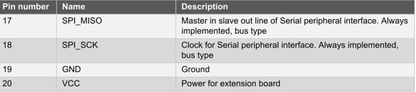
Pin number Name Description
17 SPI_MISO Master in slave out line of Serial peripheral interface. Always
implemented, bus type
18 SPI_SCK Clock for Serial peripheral interface. Always implemented,
bus type
19 GND Ground
20 VCC Power for extension board
2.3.2 Xplained Pro power header
The power header can be used to connect external power to the Xplained Pro kit. The kit will automatically detect and switch to the external power if supplied. The power header can also be used as supply for external peripherals or extension boards. Care must be taken not to exceed the total current limitation of the on-board regulator for the 3.3V regulated output. To locate the current measurement header, please refer to Figure 2-5, “Typical Xplained Pro Power Connections”
Table 2-3. Power header PWR
Pin number PWR header Pin name Description
1 VEXT_P5V0 External 5V input
2 GND Ground
3 VCC_P5V0 Unregulated 5V (output, derived
from one of the input sources)
4 VCC_P3V3 Regulated 3.3V (output, used as
main power for the kit)
Note If the board is powered from a battery source it is recommended to use the PWR header. If there is a power source connected to EDBG USB, the EDBG is activated and it will consume more power.
2.3.3 Xplained Pro segment LCD extension connector
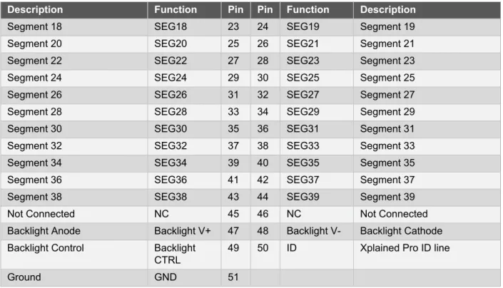
Xplained Pro MCU boards that have a microcontroller that supports segment LCDs contain a 51-pin segment LCD extension connector. This connector is implemented with HIROSEs DF-9 series. Xplained Pro MCU boards use the male version DF9-51P-1V(69) and Xplained Pro extension boards use the female counterpart DF9-51S-1V(69). This header has a standardized pin-out as shown in Table 2-4, “Xplained Pro segment LCD extension connector definition”.
Note All pins are not connected on all Xplained Pro MCU boards. How many pins that are used depend on how many segments and common terminals the target MCU supports.
Table 2-4. Xplained Pro segment LCD extension connector definition
Description Function Pin Pin Function Description
Common terminal 3 COM3 1 2 COM2 Common terminal 2
Common terminal 1 COM1 3 4 COM0 Common terminal 0
Segment 0 SEG0 5 6 SEG1 Segment 1
Segment 2 SEG2 7 8 SEG3 Segment 3
Segment 4 SEG4 9 10 SEG5 Segment 5
Segment 6 SEG6 11 12 SEG7 Segment 7
Segment 8 SEG8 13 14 SEG9 Segment 9
Segment 10 SEG10 15 16 SEG11 Segment 11
Segment 12 SEG12 17 18 SEG13 Segment 13
Segment 14 SEG14 19 20 SEG15 Segment 15
Description Function Pin Pin Function Description
Segment 18 SEG18 23 24 SEG19 Segment 19
Segment 20 SEG20 25 26 SEG21 Segment 21
Segment 22 SEG22 27 28 SEG23 Segment 23
Segment 24 SEG24 29 30 SEG25 Segment 25
Segment 26 SEG26 31 32 SEG27 Segment 27
Segment 28 SEG28 33 34 SEG29 Segment 29
Segment 30 SEG30 35 36 SEG31 Segment 31
Segment 32 SEG32 37 38 SEG33 Segment 33
Segment 34 SEG34 39 40 SEG35 Segment 35
Segment 36 SEG36 41 42 SEG37 Segment 37
Segment 38 SEG38 43 44 SEG39 Segment 39
Not Connected NC 45 46 NC Not Connected
Backlight Anode Backlight V+ 47 48 Backlight V- Backlight Cathode
Backlight Control Backlight
CTRL 49 50 ID Xplained Pro ID line
Ground GND 51
2.3.4 Xplained Pro LCD connector
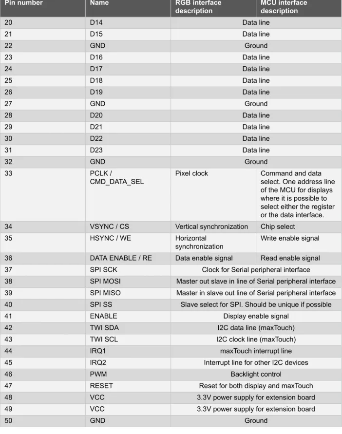
The LCD connector provides the ability to connect to display extensions that have a parallel interface. The connector implements signals for a MCU parallel bus interface and a LCD controller interface as well as signals for a touchcontroller. The connector pin-out definition is shown in Table 2-5, “Xplained Pro LCD connector”. Note that usually only one display interface is implemented, either LCD controller or the MCU bus interface. A FPC/FFC connector with 50 pins and 0.5mm pitch is used for the LCD connector. The connector
(XF2M-5015-1A) from Omron is used on several designs and can be used as a reference. Table 2-5. Xplained Pro LCD connector
Pin number Name RGB interface
description MCU interfacedescription
1 ID Communication line to ID chip on extension board.
2 GND Ground 3 D0 Data line 4 D1 Data line 5 D2 Data line 6 D3 Data line 7 GND Ground 8 D4 Data line 9 D5 Data line 10 D6 Data line 11 D7 Data line 12 GND Ground 13 D8 Data line 14 D9 Data line 15 D10 Data line 16 D11 Data line 17 GND Ground 18 D12 Data line 19 D12 Data line
Pin number Name RGB interface
description MCU interfacedescription
20 D14 Data line 21 D15 Data line 22 GND Ground 23 D16 Data line 24 D17 Data line 25 D18 Data line 26 D19 Data line 27 GND Ground 28 D20 Data line 29 D21 Data line 30 D22 Data line 31 D23 Data line 32 GND Ground 33 PCLK /
CMD_DATA_SEL Pixel clock Command and dataselect. One address line of the MCU for displays where it is possible to select either the register or the data interface.
34 VSYNC / CS Vertical synchronization Chip select
35 HSYNC / WE Horizontal
synchronization Write enable signal
36 DATA ENABLE / RE Data enable signal Read enable signal
37 SPI SCK Clock for Serial peripheral interface
38 SPI MOSI Master out slave in line of Serial peripheral interface
39 SPI MISO Master in slave out line of Serial peripheral interface
40 SPI SS Slave select for SPI. Should be unique if possible
41 ENABLE Display enable signal
42 TWI SDA I2C data line (maxTouch)
43 TWI SCL I2C clock line (maxTouch)
44 IRQ1 maxTouch interrupt line
45 IRQ2 Interrupt line for other I2C devices
46 PWM Backlight control
47 RESET Reset for both display and maxTouch
48 VCC 3.3V power supply for extension board
49 VCC 3.3V power supply for extension board
50 GND Ground
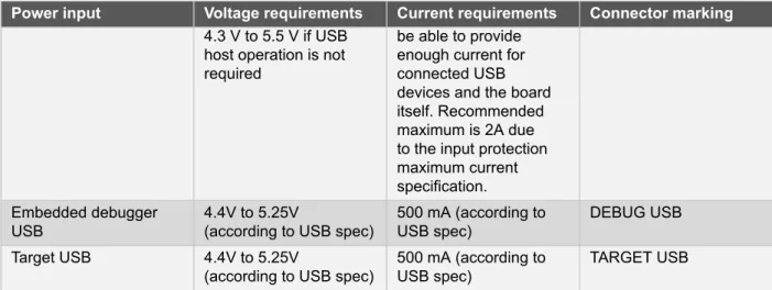
2.4
Power specifications
The Xplained Pro kit can be powered either by USB or by an external power source through the 4-pin power header, marked PWR. This connector is described in “Xplained Pro power header” on page 10. The
available power sources and specifications are listed in Table 2-6, “Power sources for Xplained Pro”. Table 2-6. Power sources for Xplained Pro
Power input Voltage requirements Current requirements Connector marking External power 5V +/- 2 % (+/- 100mV)
Power input Voltage requirements Current requirements Connector marking 4.3 V to 5.5 V if USB
host operation is not required
be able to provide enough current for connected USB devices and the board itself. Recommended maximum is 2A due to the input protection maximum current specification. Embedded debugger
USB 4.4V to 5.25V(according to USB spec) 500 mA (according toUSB spec) DEBUG USB
Target USB 4.4V to 5.25V
(according to USB spec) 500 mA (according toUSB spec) TARGET USB
The kit will automatically detect which power sources are available and choose which one to use according to the following priority:
1. External power
2. Embedded debugger USB 3. Target USB
Note External power is required when the 500mA through the USB connector is not enough to power a connected USB device in a USB host application.
As of now all Xplained Pro MCU kits are powered by 5.0V input that is reulated to a 3.3V power supply for the EDBG, MCU and extension headers/connectors.
In the future new Xplained Pro MCU kits will get support for variable voltages to supply the target MCU and the extension headers/connectors.
Figure 2-5. Typical Xplained Pro Power Connections
2.5
Extension board templates
Extensions enable demonstration of MCU features that are not placed on the MCU board, e.g. sensors, displays, LEDs and push buttons. Various standard and kit specific extensions are presented in the following sections.
A future release of this document will include Altium templates for Xplained Pro extension boards.
2.5.1 Designing a board with the standard extension connector
The following sections contain information about standard extension sizes used by Atmel. The holes referred to as "test jig holes" are used by Atmel during manufacturing to align the board in a test fixture, these holes can
safely be removed if they are not needed. The circles shown in the component placement circles are rubber feet placed on the bottom side of the boards. Keep in mind that following these templates will ensure that the boards will physically fit on all Xplained Pro kits.
Extension template 1
This is the most basic extension module and will fit all MCU boards. This means that this extension is the preferred module when starting a design.
Features:
● 30mm x 50mm
● 1 female standard extension header
● ID system
● 2 mounting holes with GND
● 2 test jig holes
● 2 rubber feet
Figure 2-6. Standard extension 1 3D view
Figure 2-7. Standard extension 1 component placement
1
5
,0
0
(
m
m
)
Extension Connector8,60 (mm)
4
,4
0
(
m
m
)
3,80 (mm)
Figure 2-8. Standard extension 1 mechanical dimensions
3
,5
0
(
m
m
)
2
,3
5
(
m
m
)
22,62 (mm) 6,50 (mm)Ø 2,00 (mm)
50,00 (mm)
7,38 (mm)8,00 (mm)
13,25 (mm)
3
0
,0
0
(
m
m
)
Ø 2,70 (mm)
2,35 (mm)
Extension template 2Compared to the basic default extension, this extension adds a power connector to the design. The extension type can be used if access to the power inputs/outputs of the MCU board is required.
● 45mm x 50mm
● 1 female standard expansion header
● 1 female power header
● ID system
● 2 mounting holes with GND
● 2 test jig holes
● 2 rubber feet
Figure 2-10. Standard extension 2 component placement
1
5
,0
0
(
m
m
)
4
0
,4
0
(
m
m
)
Extension Connector Power Connector3,80 (mm)
3,80 (mm)
Figure 2-11. Standard extension 2 mechanical dimensions
1 3 ,2 5 ( m m ) 2 ,3 5 ( m m ) 3 ,5 0 ( m m ) 4 5 ,0 0 ( m m )
Ø 2,00 (mm)
50,00 (mm)
7,38 (mm)
22,62 (mm)
6,50 (mm)
8,00 (mm)
4 2 ,6 5 ( m m )Ø 2,70 (mm)
2,35 (mm)
Extension template 3
This extension is targeted for applications that require more signals than are available on one standard header e.g. when more than 2 ADC or PWM signals are needed. Please note that this extension might not fit all MCU boards since smaller boards will not have two extension headers on one side.
● 65.55mm x 50mm
● 2 female Standard extension headers
● ID system
● 2 mounting holes with GND
● 2 test jig holes
● 2 rubber feet
Figure 2-13. Standard extension 3 component placement
5
0
,5
6
(
m
m
)
Extension Connector 2 Extension Connector 11
5
,0
0
(
m
m
)
3,80 (mm)
3,80 (mm)
Figure 2-14. Standard extension 3 mechanical dimensions 1 3 ,2 5 ( m m ) 3 ,5 0 ( m m ) 2 ,3 5 ( m m ) 4 8 ,8 1 ( m m ) 6 3 ,2 0 ( m m ) 50,00 (mm) 6,50 (mm) Ø 2,00 (mm) 8,00 (mm) 42,94 (mm) 58,18 (mm) 6 5 ,5 5 ( m m ) Ø 2,70 (mm) 2,35 (mm) Extension template 4
This extension is the same as extension 3 except for the additional power header.
● 80.55mm x 50mm
● 2 female standard extension headers
● 1 female power header
● ID system
● 2 mounting holes with GND
● 2 test jig holes
Figure 2-16. Standard extension 4 component placement
7
5
,9
6
(
m
m
)
1
5
,0
0
(
m
m
)
5
0
,5
6
(
m
m
)
Extension Connector 2 Power Connector Extension Connector 13,80 (mm)
3,80 (mm)
Figure 2-17. Standard extension 4 mechanical dimensions 3 ,5 0 ( m m ) 2 ,3 5 ( m m ) 8 0 ,5 5 ( m m ) 4 8 ,8 1 ( m m ) 6,50 (mm) Ø 2,00 (mm) 50,00 (mm) 1 3 ,2 5 ( m m ) 8,00 (mm) 42,94 (mm) 58,18 (mm) 7 8 ,2 0 ( m m ) Ø 2,70 (mm) 2,35 (mm) Extension template 5
This board size is designed to fit on all Xplained Pro MCU boards, but with an orientation for the header at the bottom of the Xplained Pro MCU board. Note that the board is too wide to be connected next to another extension board on the right hand side
Features:
● 60mm x 60mm
● 1 female standard extension header
● ID system
● 4 mounting holes with GND
● 2 test jig holes
Figure 2-19. Standard extension 5 component placement
30,00 (mm)
3
,8
0
(
m
m
)
Extension ConnectorFigure 2-20. Standard extension 5 mechanical dimensions 6 0 ,0 0 ( m m ) Ø 2,00 (mm) 37,62 (mm) 22,38 (mm) 3,50 (mm) Ø 2,70 (mm) 28,25 (mm) 2 ,3 5 ( m m ) 2,35 (mm) 8 ,0 0 ( m m ) 6,5 0 ( m m ) 60,00 (mm)
2.5.2 Designing a board with the segment LCD connector
Board size constraint
Xplained Pro MCU boards will support segment LCD boards up to 45mm x 30mm with the Hirose
DF9-51S-1V(69) connector in the absolute center of the board on the bottom layer. Figure 2-21, “Segment LCD board size constraint” shows an example drawing of a segment LCD board. The constraints are introduced to avoid collision with other on-board peripherals on Xplained Pro MCU boards. When the Hirose connectors on a MCU board and segment LCD board is stacked the total height is 4.3mm, any through hole pins on a segment LCD should not be too long as they may collide with resistors/capacitors on the MCU board.
Important Segment LCD boards should not be larger than 45mm x 30mm with the Hirose connector located at the center of the board. Boards larger than this may collide with components on a Xplained Pro MCU board.
Figure 2-21. Segment LCD board size constraint
2.5.3 Designing a board with the LCD connector
Atmel has not designed any extension boards with the LCD connector. Please contact Atmel if you are interested in creating an extension board using this connector.
3.
How to Integrate a Xplained Pro Extension in Atmel Studio
3.1
Xplained Pro Landing Page
When a Xplained Pro MCU kit is connected to a computer running Atmel Studio a landing page for the kis is shown. Figure 3-1, “Xplained Pro Landing Page in Atmel Studio” shows a landing page for SAM4S Xplained Pro with PROTO1-, IO1- and OLED1 Xplained Pro connected. The landing page provides the connected kits name, a picture of the kit, a description of the kit, links to relevant documentation/websites and all the information stored in the Xplained Pro ID chip located on the extension modules.
Figure 3-1. Xplained Pro Landing Page in Atmel Studio
A future version of the Atmel XDK will contain an API for adding kit information to the landing page in Atmel Studio.
Any developers that would like to add information about an Xplained Pro extension to Atmel Studio has to contact Atmel via e-mail: [email protected] with landing page information and a picture of the kit as shown in the figure above. The landing page uses the name of the kit stored in the ID chip as a key to display the correct information, it is therefore important that Atmel knows the exact name that will be programmed into the chip.
4.
How to Integrate Code Examples for a Xplained Pro Extension in
Atmel Studio
A future version of this document will describe how to integrate code examples for a Xplained Pro extension in Atmel Studio.
A.
Appendix
A.1
Document Revision History
Doc. Rev. Date Comment
C 06/2013 Restructured the document. Added information about Xplained Pro ID device programming and integration to Atmel Studio
B 03/2013 Added a new chapther about Atmel Studio integration
A 02/2013 First release
A.2
xpro_id Version History
This chapter contains the changelog for the xpro_id python package used to program/read Xplained Pro ID devices.
A.2.1 Version 0.5
Atmel Corporation 1600 Technology Drive, San Jose, CA 95110 USA T: (+1)(408) 441.0311 F: (+1)(408) 436.4200 | www.atmel.com © 2013 Atmel Corporation. All rights reserved. / Rev.: 42091C-MCU-05/2013
Atmel®, Atmel logo and combinations thereof, Enabling Unlimited Possibilities®, and others are registered trademarks or trademarks of Atmel Corporation or its subsidiaries. Other terms and product names may be trademarks of others.
Disclaimer: The information in this document is provided in connection with Atmel products. No license, express or implied, by estoppel or otherwise, to any intellectual property right is granted by this document or in connection with the sale of Atmel products. EXCEPT AS SET FORTH IN THE ATMEL TERMS AND CONDITIONS OF SALES LOCATED ON THE ATMEL WEBSITE, ATMEL ASSUMES NO LIABILITY WHATSOEVER AND DISCLAIMS ANY EXPRESS, IMPLIED OR STATUTORY WARRANTY RELATING TO ITS PRODUCTS INCLUDING, BUT NOT LIMITED TO, THE IMPLIED WARRANTY OF MERCHANTABILITY, FITNESS FOR A PARTICULAR PURPOSE, OR NON-INFRINGEMENT. IN NO EVENT SHALL ATMEL BE LIABLE FOR ANY DIRECT, INDIRECT, CONSEQUENTIAL, PUNITIVE, SPECIAL OR INCIDENTAL DAMAGES (INCLUDING, WITHOUT LIMITATION, DAMAGES FOR LOSS AND PROFITS, BUSINESS INTERRUPTION, OR LOSS OF INFORMATION) ARISING OUT OF THE USE OR INABILITY TO USE THIS DOCUMENT, EVEN IF ATMEL HAS BEEN ADVISED OF THE POSSIBILITY OF SUCH DAMAGES. Atmel makes no representations or warranties with respect to the accuracy or completeness of the contents of this document and reserves the right to make changes to