2010 12th Electronics Packaging Technology Conference
Active Alignment for Cameras in Mobile Devices and Automotive Applications
Dr. Karl Bitzer Product Management DELO Industrial Adhesives
DELO Allee 1 86949 Windach - Germany
www.delo.de karl.bitzer@delo.de
Andre By Chief Technology Officer Automation Engineering Incorporated
299 Ballardvale Street Wilimington, MA 01887 US
www.aeiboston.com aby@aeiboston.com
Abstract
The increased use of cameras within mobile devices such as cellular phones as well as for automotive and other applications is spurring innovations in pixel density, lens quality and power usage. As required quality performance of the camera modules improves, the requirements for more accurate assembly techniques increase as well. Within the production process, joining methods as well as manufacturing machines have to fit together. A new technological solution was therefore created that advances the accuracy of this alignment process of camera modules and results in increased performance and yield
Traditional Methods for Camera Module Assembly Camera modules consist of two primary components: a CMOS camera sensor on a circuit board and an optically aligned and attached lens barrel assembly. Traditionally the manufacturing process inserts a threaded lens barrel into the camera housing, with the operator threading the lens barrel into the housing while monitoring the camera image on a video screen to align the lens for optimal image quality. With this type of design, the manufacturer only performs alignment of the lens assembly to the sensor in one dimension- along the optical (Z) axis.
Fig.1. Typical Camera Module Packaging for Mobile Devices
For new generations of camera modules, alignment of the other two linear and additional two rotational axes becomes critical. Achieving a sharp image over the full plane of the sensor and throughout the full range of zoom capability requires accurate alignment of the lens to the sensor in not just one, but five degrees of freedom. This technology becomes essential as both camera-module resolutions and end customer expectations of image quality increase.
Multi-Axis Active Optical Alignment
Multi-axis active optical alignment of the lens/sensor assembly compensates for variability inherent to upstream manufacturing processes, producing a more consistent product with higher performance and yield. This alignment approach for cameras presents great challenges for the adhesive and the joining method of optics in camera modules for mobile devices and other applications. This requires the alignment of optical components such as mirrors, lenses or prisms during fixing to a substrate or structure in the camera module. To achieve this, the components are placed on an adhesive layer. The adhesive must remain liquid until the proper alignment is achieved. Once the optical component has obtained its correct position for optimal image quality, the adhesive must cure quickly in order to fix the component in place.
As the components are precisely aligned and the adhesive then cured, the adhesive may shrink in the Z direction. This can be compensated for by characterizing the level of shrinkage experimentally and then moving the appropriate amount away from the direction of shrinkage prior to curing. At the same time, no decomposition products may deposit on the optical component or form corrosion on surrounding electrical components during adhesive curing. This can be a significant obstacle because shadowed areas of the dispensed adhesive cannot be completely cured with purely UV light-curing adhesives. This circumstance results in reduced reliability and increased waste or scrap rates in the production process, particularly if the adhesive is too liquid, which leads to out-gassing and lower reliability.
2010 12th Electronics Packaging Technology Conference Fig. 2 below shows the working principle of the multi-axis
active optical alignment process.
Step 1: Adhesive Dispense
Step 2: Positioning of the Lens Housing
Step2: Pla
Step 3: Active Optical Alignment
Step 4: Initial UV “Tack” Cure
Step 5: Secondary Heat Cure
Fig.2. Steps for Multi-Axis Active Alignment and Attach
New Technologies
To establish a new process that fulfils all requirements, DELO developed a special adhesive for automation supplier Automation Engineering Incorporated (AEi). AEi developed a series of machines starting in 2005 named CMAT (Camera Module Align and Test) to implement the associated active alignment. The CMAT stations are unique as they use a five or six axis active optical alignment with AEI proprietary algorithms, developed based on earlier photonic active alignment stations first deployed by AEI in the late 1990s for telecommunications. AEI later adapted these algorithms and corresponding alignment stations to actively align and assemble lenses to camera modules for mobile devices. This alignment and attach approach provides optimal focus and image quality throughout the camera image plane.
To achieve the best overall camera alignment the CMAT machine executes the following primary steps in sequence:
Dispense adhesive at the top of the sensor die or camera housing (depending on specifics of camera package design).
Position the lens barrel over the nominal center of the camera sensor and above the expected Z focus position range.
Scan though positions downward and evaluate the gradient focus scores at multiple regions in the image plane and at multiple lens positions.
Based on acquired focus scores through the lens scan, determine the best focus position in 5 or 6 degrees of freedom and move to that position.
Verify proper focus results.
Apply UV light for initial tack cure.
The CMAT machine supports a substantial set of configurable thresholds and process parameters for password authorized users to optimize this sequence for a given camera design. Adhesives Requirements for Active Optical Alignment
DELO developed new adhesive technologies that perfectly close the gap and also enable curing in shadowed areas which had not previously been practical. A new dual-curing adhesive was specifically designed for the active alignment process. The customized adhesive perfectly meets the application’s needs. This dual-curing adhesive is pre-fixed with light in a few seconds and is subsequently exposed to a low temperature of only 85°C in order to heat-cure adhesive in the shadowed areas of the component.
Thanks to the brief initial fixing with UV light, long curing times can be omitted. In other words, the customers benefit from fast cycle times, high throughput and low-temperature curing when using temperature-sensitive components. Different tests were made in the DELO labs to test the dual-curing adhesive, such as an 85/85 test over 1000 hours or different shrinkage tests. The results show that the dual-curing adhesive fulfils these requirements. A broad range of customers are already using this technique which is suitable for mass production.
2010 12th Electronics Packaging Technology Conference Bonded Materials and Flow Behaviour
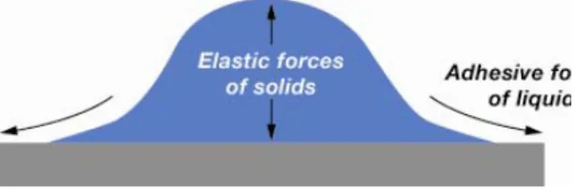
The adhesive can be bonded to several different materials. One example is the bonding between glass and the lens barrel which is made of filled plastic or metal. The adhesive will have an adapted flow behaviour to the active alignment process. To do this, it is important that the flow behaviour and the elastic force of the adhesive remain stable over a certain period of time. It is required that the adhesive changes its shape minimally after the dispensing process. The formulation of the adhesive must be done in such a way that the surface tension of the adhesive is in a defined relationship to the aspect ratio of the dispensed volume. This is shown in Figure 3 for a camera packaging that uses the adhesive to bond the lens directly to a cover glass over the camera sensor. This is typical for wafer level and other small format cameras.
Fig. 3. Paste Adhesive Dispensed With Solid Filler The adhesive is dispensed on the glass before attaching the lens. As shown in Figure 3 the elastic properties of the adhesive enable a thinner higher bead. There has to be a certain aspect ratio after dispensing. This is important to provide sufficient volume of adhesive in the limited space. It also ensures that the adhesive stands-up high enough to contact the lens.
If the adhesive is not matched to the requirements of the process, it spreads out low across the cover glass and it will not contact the lens all the way around leaving discontinuities in the joint. Purely liquid adhesives have adhesion together in places where they contact the lens leaving discontinuities or gaps in the joint where there is no contact
Fig.4. Paste Adhesive During Downward Motion of Lens During the active alignment the lens must be moved up and down to find the optimal alignment position which can lead to migration of the adhesive away from the adhesive joint.
Adhesive is squeezed out from the joint during the down motion. As shown in Figure 4, the adhesive will build up near the joint if there are solid fillers. However, if there are no fillers, the adhesive forces will tend to spread the liquid out across the cover glass and up the side of the lens.
Shadowed Zones
It can be further noted that there are often different shadow zones after the attaching process. The shadow zones can lead to the out-gassing of the uncured material and the lenses may be negatively impacted after a period of time in service. In addition to this, the reliability tests produce inferior results compared to the active alignment solution with the Dualbond material developed by DELO. A further advantage of the Dualbond material is the potential higher throughput since the initial UV fixation of the material can be done within as little as 2 to 3 seconds.
Fig. 5. Paste Adhesive During Upward Motion of Lens When the lens moves up following downward motion, the developed adhesive will be sucked back into the joint if it is near enough to the joint. This results in a good fillet which significantly improves joint strength and reliability. The low temperature heat curing step afterwards further allows high reliability. The fillet distributes stress to eliminate stress concentrations that may occur in this region. Stress concentrations can initiate cracks that propagate through the joint causing joint failure.
If there are only liquid fillers in the adhesive the material will migrate away from the joint on the downward motion of the lens and when the lens moves back up the adhesive will not be sucked back into the joint. This results in a joint without a fillet which has significantly reduced strength and low reliability.
Dispensing
The adhesive was developed in such a way that it can be used in combination with different dispensing possibilities. The CMAT machines use either a jetting dispense or a screw dispenser to dispense the adhesive. The adhesive is forced through a thin diameter nozzle. The velocity of the fluid flowing through the nozzle and the quick cut off of flow causes a drop to be released from the jet and ejected towards the dispensing surface.
2010 12th Electronics Packaging Technology Conference Out-Gassing
Acrylic adhesives tend to out-gas when heated and should not be used in combination with the active alignment process. The out-gassing material can condense on the optical surfaces and effect their performance in service over time. DELO patented the new chemistry which was developed for the active alignment process. This adhesive type has very low out-gassing during the curing process and after the heat curing step. Thanks to the two step curing mechanism (UV light and heat) there is no liquid adhesive in the component. DSC measurement shows a fully cured adhesive after 20 min at 85 °C in a batch oven process.
Shrinkage
Shrinkage occurs in all adhesives during UV and the heat curing step. This shrinkage in the lens joint causes a shift in the final position of the lens. The average shrinkage can be measured for a particular geometry and the CMAT machine offsets the position of the lens prior to curing, to compensate for the shrinkage, such that the lens returns to the optimum position after curing. The shrinkage is not perfectly repeatable, so the final position of the lens will have some error even when using a pre-cure compensation. The greater the shrinkage the greater the error will be. Thus, DELO developed for AEi an adhesive material that has very little shrinkage in the z- direction. The following results indicate the benefits of this adhesive:
Small shrinkage of only about 10 microns during cure
Small variation in shrinkage which can be compensated for by using a side looking machine vision camera prior to cure to measure bond gap
Reliability Tests
Consumer and automotive cameras typically connected to a circuit board use SMT (Surface Mount Technology) so the camera must be able to survive the temperatures in an SMT reflow oven. The adhesive must in some cases withstand temperatures of 260 °C over 3 minutes for three times. This is particularly true to meet standards such as the Telecordia GR-468 reliability assurance requirements. The properties of the adhesive have to be developed in a manner which insures that the reflow does not change the shrinkage of the material after the alignment process. This will result in a de-focussing of the complete camera.
Many customers are also doing drop tests, 85/85 relative humidity and temperature tests. The package has to be developed in such a way that the shear values and impact resistance values of the adhesive are matched to the requirements of the industry.
Application Example A: Alignment for Stereoscopic Boroscope Camera
The alignment and attach for stereoscopic boroscope cameras has different challenges. The alignment of two
optical lenses to two sensors must be with optimal focus and additionally, with pixel to pixel alignment in the image plane. However, this must be to a restrictive tolerance since the acquired images are then used to generate 3D image results. To achieve this, the active alignment approach requires the electrical engagement of both sensors simultaneously as shown in Figure 6.
Fig. 6. Example Dual Sensor Arrangement for Stereoscopic Boroscope Camera
Here, a parallel electrical and mechanical connection to the camera is required. This is implemented in a more complex nest/fixture that accommodates the interface to both sensors. The alignment approach is similar to single sensor cameras except that aligning optics for the second sensor must be evaluated and adjusted for any shift in adhesive attach resulting in the first optical alignment
Application Example B): Alignment for Camera with Matrix of Sensors
For a matrix sensor camera implementation, the alignment and attach has parallel challenges. The alignment must also be with best focus for a given sensor but also with pixel to pixel alignment in the image plane from sensor to sensor. There is again a more restrictive tolerance since the acquired images must then be coincident. For best results, the active alignment approach requires that electrical engagement of all sensors be available simultaneously. This of course requires a more complex electrical interface implementation, as shown in Fig. 7.
2010 12th Electronics Packaging Technology Conference Here, a parallel electrical and mechanical connection to the
camera is again required. This is implemented in a nest/fixture that accommodates the interface to all of the sensors. The alignment approach is again similar to that of single sensor cameras. However, in this case, the focus of each sensor is balanced laterally with respect to all sensors in the matrix. Focus scores at the center of each sensor are evaluated and compared to a minimum threshold to achieve required alignment results.
Active Alignment for Single and Multi-Sensor Cameras in Mass Production
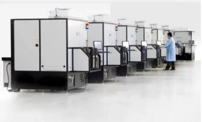
Fig. 8 below shows mass production CMAT automated align and assembly machines that use AEi’s 5 and 6 degree of freedom active alignment for either single sensor or multi-sensor cameras. These stations are capable of producing cameras for a variety of applications in automotive cameras, consumer and professional still cameras and video cameras, advanced sensor cameras, and cameras for boroscopes and endoscopes.
Fig. 8. Example of CMAT Mass Production 5 and 6 DOF Active Alignment Stations
Conclusions
This paper illustrates how a close interaction between an automation equipment supplier and the adhesive supplier can be a catalyst for the development of a new and improved optical alignment and attach process. Short adhesive development cycle times during the development of the adhesive are key to create a highly reliable new process. It was shown that the use of Dualbond materials have various benefits compared to pure UV light cure material often used in this industry. It was also shown that development and implementation of a more advanced optical alignment approach can maximally exploit the advantages and benefits of these adhesives to make higher quality camera modules for multiple industry applications.
References
1. Downey, D. F., Ion Implantation Technology, Prentice-Hall (New York, 1993), pp. 65-67.
2. Wasserman, Y, “Integrated Single-Wafer RP Solutions for 0.25-micron Technologies,” IEEE Trans-CPMT-A, Vol. 17, No. 3 (1995), pp. 346-351.
3. Shu, William K., “PBGA Wire Bonding Development,” Proc 46th Electronic Components and Technology Conf, Orlando, FL, May. 1996, pp. 219-225.