Dual Frequency Reflectarray Antenna Based on
Method of Moment Mathematical Model
N. H. Sulaiman* and M. Y. Ismail
Wireless and Radio Science Center (WARAS)Universiti Tun Hussein Onn Malaysia 86400 Parit Raja, Johor, Malaysia
[email protected], [email protected],
Abstract—In this work, a detailed analysis of dual frequency X-band reflectarray antenna using dual gap configuration on the rectangular patch element is presented. A novel method of moment mathematical model of dual frequency operation based on different dielectric material has been introduced in this paper. The analytical modeled simulations and mathematical model of dual frequency using Roger RT/d 5880 and FR-4 as dielectric substrate operation offers a good agreement. The numerical analysis results based on Finite Integral Method (FIM) computer model of CST MWS show that employing dual gap on the rectangular patch element improves the static phase range up to 343.5º. The design and measurement setup of proposed configurations are discussed in this paper. The comparisons between simulations, mathematical model and measured results have also been presented.
Keywords-dual frequency reflectarray antenna; dual gap; static phase range; phase errors.
I. INTRODUCTION
Modern communication systems such as satellite links, Global Position Systems (GPS) and radar communication systems often require compact and low cost antennas with dual frequency operation [1]. Moreover, dual frequency operation significantly improves the system performance due to the size and cost of antenna [2].
The conventional antenna systems such as parabolic reflectors and phased array antennas have been generally used for the high gain applications. However, some significant disadvantages of conventional systems are bulky structure, complex maintenance and higher cost. Therefore, a reflectarray antenna has been introduced as a possible replacement to the conventional antennas [3-5].
The reflectarray using printed microstrip patch antennas have been developed to achieve low reflecting surface profile, small antenna mass and reduced manufacturing cost [6]. However, the reflectarray antenna has limited bandwidth performance due to the narrow band of reflectarray antenna elements and spatial phase delays. In order to overcome the limitation of the bandwidth performance, high static phase range with less phase errors performance should be achieved. In order to increase static phase range, dual frequency operation has identified to enhance bandwidth performance [7]. Moreover, dual frequency antennas have shown significant
advantages particularly mobile communication system and radar applications. Considerable researches on dual frequency antenna operation have been carried out by previous researchers such as using slots in the patch and compact stacked patch antennas [8-10], using concentric split rings patch antennas and using stacked configurations with two separated feeds for each frequency [11]. But, it can be seen that dual frequency can be achieved by introducing complicated method which increases the design complexity of the system. Due to these difficulties, a simple technique to obtain dual frequency is required to be proposed.
In this work, the comparison of dual frequency performance based on Finite Integral Method (FIM) and Method of Moment (MoM) has been provided to investigate the feasibility of dual frequency operation by employing dual gap on the rectangular patch reflectarray antenna. Additionally, a new formulation of dual frequency operation has been introduced based on the possibility of obtaining dual frequency operation using dual gap structure.
II. DESIGN AND METHODOLOGY
A. Design and simulation work
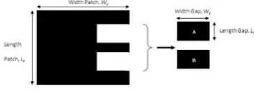
A rectangular patch element has been designed using Rogers Rt/d 5880 as a dielectric substrate. Commercially available CST computer model has been used to design a unit cell element with proper infinite boundary conditions. Rectangular patch reflectarray antenna was constructed on a 0.787 mm thick dielectric substrate with patch element dimensions Lp=10.0 mm x Wp =11.5 mm. In order to investigate the possibility of realizing dual frequency antenna, dual gap configurations has been introduced on a rectangular patch element as shown in Fig. 1.
Figure 1. Geometrical dimensions of rectangular patch element with dual gap configurations
[image:1.595.338.521.621.686.2]Fig. 1 shows the details of dual gap configuration on the rectangular patch element. In this work, gap A and gap B as shown in Fig. 1 have the same dimensions of Wg= 2.00mm x Lg= 1.00mm. In order to observe the effect of introduction of dual gap configuration, the model design has been simulated in the X-band frequency range. The width, Wgof the gap is varied from 2.00mm to 3.20mm while the length, Lgof the dual gap is kept constant at 1.00mm. From the dual gap performance, the formulation of dual frequency has been derived which considers the frequency for particular width of dual gap obtained by using the formula as shown in Equation (1).
s pd s
s p
f
f
f
w
f
w
w
'
(1)Where,
fdis desired frequency for the specific frequency of dual gap fsis secondary frequency
fpis the primary frequency
ǻZis the interval of the width variation
In order to verify the validity of this formula, computer programming software of Turbo C++ has been used and a set of results from different widths of dual gap has been generated. In order to show the dual frequency operation in X-band frequency range, variable width of dual gap has been generated from 2.80mm to 3.20mm.
From Fig. 2, it can be seen that the gap with the width, wg=3.20mm offers -0.98dB reflection loss at 8.31 GHz while the second resonant frequency at 11.98 GHz offers -2.05dB of reflection loss. The reason behind the difference of loss performance is due to the modification of the surface current and electric field distributions on the surface of patch element and substrate region respectively. It has been demonstrated that by using different widths of dual gap, dual frequencies have been obtained in which dual frequency can be easily adjusted by changing the width of dual gap.
Figure 2. Dual frequency by using variable width of dual gap, wg
In this work, reflection phase curve has been plotted in Fig. 3. It is also shown that by employing dual gap on the rectangular patch element, the feasibility of dual frequency operation can
be obtained with the highest static phase range performance of 343.5 ° where 3.20mm of width dual gap has been introduced.
Figure 3. Dual frequency by using variable width of dual gap, wg
B. Fabrication samples
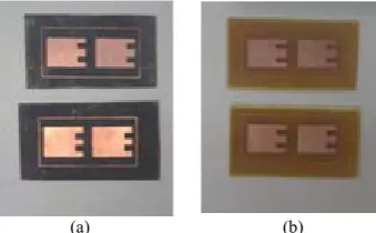
In order to validate the feasibility of dual frequency operation obtained from simulations, various samples of dual gap embedded on the rectangular patch element unit cells have been printed on Roger 5880 and FR-4 dielectric material. The fabricated samples are shown in Fig. 4.
(a) (b)
[image:2.595.310.525.95.242.2]Figure 4. Fabricated samples of dual gap on the rectamgular patch element (a) Roger 5880 (b) FR-4
Fig. 4 shows the fabricated samples of two identical size patch elements unit cell reflectarray. The fabrication of this sample has been done by using photolithography process. For each design, two patch elements of identical size are fabricated where the element spacing d is kept at half wavelength to reduce mutual coupling effects. The scattering parameters measurements of the designed samples have been carried out by using vector network analyzer with waveguide simulator technique [12].
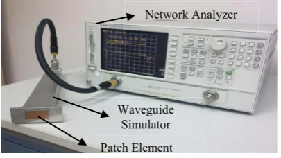
C. Measurement Setup
Scattering parameter measurement was carried out using vector network analyzer. By connecting the waveguide simulator to the vector network analyzer via coaxial cable and waveguide adapter, scattering behavior such as reflection loss and reflection phase has been obtained. The complete measurement setup is shown in Fig. 5.
-2.5 -2 -1.5 -1 -0.5 0
8 8.5 9 9.5 10 10.5 11 11.5 12
Frequency (GHz)
R
e
fl
ect
io
n
L
o
ss (
d
B
)
w = 2.80mm w = 3.00mm w = 3.20mm
0 120 240 360 480 600 720
6 7 8 9 10 11 12 13 14
Frequency (GHz)
R
efl
ec
ti
o
n
Ph
as
e (D
eg
re
e)
w = 2.80mm
w = 3.00mm
[image:2.595.347.517.353.458.2] [image:2.595.41.254.507.658.2]Figure 5. Measurement setup for scattering parameters measurements
As depicted in Fig. 5, two patch elements are inserted into the aperture of waveguide simulator. The investigations for dual gap reflectarray element have been carried out to investigate the performance of reflectarray antenna. Reflection phase and reflection loss have been characterized in order to analyze the scattering parameter behaviour of reflectarray elements.
III. MATHEMATICAL MODELING OF DUAL FREQUENCY
In this section, the mathematical model based on method of moment (MoM) for dual frequency operation using different dielectric materials has been presented to verify result obtained from CST MWS using Finite Integral Method. The dielectric materials used in this investigation are Roger RT/d 5880 and FR-4. The mathematical model has been developed based on the dielectric material properties as shown in Equation 2.
8.48 1 9.48
8.0 8.50 11.80 12.40
11.52 2 11.80
tan
17.99
;
1
;
,
1.5
tan
17.99
;
e r
g
g r
e r
g
A
f
fr
f
w
RL
w
f
f
A
f
fr
f
w
H
G
H
H
G
°
°
°°
®
°
°
°
°¯
(2)
Where;
RL= Reflection loss Ae= Aperture Size
İr= dielectric constant
WDQį= tangent loss wg= width of the dual gap
The reflection loss of dual frequency performance can be obtained by using proposed relation given in Equation 2. It can be observed that the reflection loss of first resonant frequency (fr1) and second resonant frequency (fr2) depend on the aperture size (Ae) and width of the dual gap (wg). It is also shown that the reflection loss is inversely proportional to the width of the dual gap. The properties of both dielectric substrates used are shown in Table I. This mathematical model
based on material properties has been derived to predict dual frequencies performance.
TABLE I. MATERIALS PROPERTIES OF DIELECTRIC SUBSTRATE
Materials &RQVWDQWİDielectric
r)
Tangent
/RVVWDQį
Thickness (mm)
Roger 5880 2.2 0.0009 0.787
FR-4 4.3 0.0250 1.600
As shown in Table I, it can be observed that dielectric constant and loss tangent for each material are different which affect the reflection performance of reflectarray antenna. The comparison between simulations and mathematical model are discussed in the next sections.
IV. RESULTS AND DISCUSSION
A. Reflection Loss
This section provides the details of scattering measurements and comparison between the simulated and measured results. The waveguide has been used in order to represent an infinite reflectarray antenna using a two patch element unit cell.
Figure 6. Mathematical modeling of dual frequency using Roger 5880
In order to compare the dual frequencies reflectarray performance obtained using CST simulations, measured results and mathematical model, reflection loss for unit cells reflectarray antenna designed with Roger 5880 is plotted in Fig. 6. The summary of reflection loss results is shown in Table II.
TABLE II. THEREFLECTION LOSS OF DUAL FREQUENCY OPERATION
Results
Resonance 1 Resonance 2
Frequency
(GHz) Reflection Loss (dB) Frequency (GHz) Reflection Loss (dB)
Simulated 8.31 -0.99 11.98 -1.52
Mathematical
Model 8.31 -1.59 11.97 -1.83
Measured 8.38 -3.45 12.02 -4.46
From Table II, it can be observed that the first simulated resonant frequency of 8.31GHz offers -0.99dB of reflection loss as compared to mathematical model results which resonates at 8.31GHz with -1.59dB of reflection loss. A
Network Analyzer
Waveguide Simulator
Patch Element
-5.0 -4.5 -4.0 -3.5 -3.0 -2.5 -2.0 -1.5 -1.0 -0.5 0.0
8 8.5 9 9.5 10 10.5 11 11.5 12
Frequency (GHz)
R
e
fl
e
c
ti
on Los
s
(
d
B
)
[image:3.595.62.265.54.168.2] [image:3.595.311.532.324.466.2]difference between simulation and mathematical modeling results of 0.6dB has been shown in reflection loss performance. It has also be observed that the second resonant frequency of 11.98GHz with -1.52dB of reflection loss has a good agreement with the mathematical model which offers -1.83dB of reflection loss performances at 11.97GHz. It can be concluded that mathematical model for dual frequency using Roger 5880 has a good agreement between simulated and predicted results. Other than that, the mathematical model of dual frequencies using FR-4 has also been developed. In order to compare dual frequencies performance of reflectarray designed using FR-4 substrate are plotted in Fig. 7.
Figure 7. Mathematical model of dual frequency using FR-4
Fig. 7 shows the comparison between CST simulations, mathematical model and measured results. The summary of reflection loss is shown in Table III.
TABLE III. THEREFLECTION LOSS OF DUAL FREQUENCY OPERATION
Results Frequency Resonance 1 Resonance 2
(GHz) Reflection Loss (dB) Frequency (GHz) Reflection Loss (dB)
Simulated 8.80 -5.80 11.55 -3.84
Mathematical
Model 8.80 -6.24 11.55 -4.01
Measured 9.10 -27.81 11.87 -7.38
As depicted in Table III, the comparison of dual frequency performance between simulated results, mathematical modeling and measured results provides a very close agreement. It can be observed that the first simulated resonant frequency offers -5.80dB of reflection loss as compared to the mathematical model which offers -6.24dB of reflection loss at exactly the same frequency of 8.80GHz. For the second resonant frequency of 11.55GHz, simulated results offer -3.84dB while the mathematical model shows -4.01dB of reflection loss. The maximum discrepancy between simulated and formulated results is found to be 0.44dB for first resonant frequency and 0.17dB for the second resonant frequency. The difference between the simulated and mathematical model results is due to the infinite boundary conditions which are not taken into consideration during the formulation of mathematical model. Moreover the simulated and
mathematical modeling results also provide a very close agreement with the measured results. However, it can be observed that the measured results have discrepancy as compared to the simulated results. The difference between simulated and measured results for reflection loss is due to the connection and fabrication errors.
B. Reflection Phase
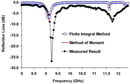
In order to represent the bandwidth performance, reflection phase curve is plotted in Fig.8. As depicted in Fig.8, the comparison of simulated and measured reflection phase curve is shown. From the reflection phase curve, static phase range and figure of merit have been analyzed. It can be observed that the measured results have a good agreement with the simulated results. It has also been shown that by introducing dual gap on the rectangular patch element dual frequency operation can be achieved with the highest static phase range performances of 343.5°. The summary of result obtained from reflection phase curve has been summarized in Table IV.
Figure 8. Simulated and measured reflection phase curve
Figure 9.
TABLE IV. THEREFLECTION OF PHASE CURVE OF DUAL FREQUENCY
OPERATION
Result
Resonance 1 Resonance 2
Static Phase Range (0)
Figure of Merit , FoM
(0/MHz)
Static Phase Range (0)
Figure of Merit , FoM
(0/MHz)
Simulated 294.40 0.269 343.5 0.284
Measured 285.10 0.264 339.4 0.281
Table IV shows the static phase range and figure of merit for dual frequency operation. As depicted in Table IV, it can be observed that the simulated result for first resonant frequency offer FoM of 0.269°/MHz with 294.40° of static phase range as compared to measured results which provides a figure of merit of 0.264°/MHz with 285.10° of static phase range. It can be seen that discrepancy between simulated and measured results is 9.3° for the first resonance frequency and 4.1° for the second
-30.0 -25.0 -20.0 -15.0 -10.0 -5.0 0.0
8 8.5 9 9.5 10 10.5 11 11.5 12
Frequency (GHz)
R
e
fl
e
c
ti
o
n
L
o
s
s
(d
B
)
Finite Integral Method
Method of Moment
Measured Result
I '
f
[image:4.595.39.262.208.353.2] [image:4.595.325.561.297.477.2]resonance of. The difference between simulated and measured results for static phase range and FoM is due to the connection and fabrication errors.
V. CONCLUSIONS
From the investigations provided in this work, it can be concluded that employing dual gap on the rectangular patch of reflectarray antenna offers significant advantages for dual frequency application that can be used for X- band applications. The mathematical modeling for dual frequency operation using different dielectric substrates has been presented. Furthermore, a novel formulation to predict dual frequency based on dual gap on the rectangular patch element using different dielectric material has also been established.
ACKNOWLEDGMENT
We would like to thank the staff of Wireless and Radio Science Centre (WARAS) of Universiti Tun Hussein Onn Malaysia (UTHM) for the technical support.
REFERENCES
[1] N. Misran, M. T. Islam, N. M. Yusop and A. T. Mobashhser, “ Design of compact dual band mirostrip antenna for ku-band application,” International Confernce on Electrical Engineering and Infromatics, Vol. 2, pp. 699-702, August, 2009.
[2] B. F. Wang and H. T. Lo, “ Microstrip antennas for dual frequency operation,” IEEE Trans. Antennas Propag.,Vol. 32,.pp. 938-943, Sept. 1984.
[3] J. A. Encinar, “Design of two-layer printed reflectarrays using patches of variable size,”IEEE Trans. Antenna Propagat., Vol. 49, No. 10, pp.1403-1410, 2001.
[4] J. A. Encinar, “Design of two-layer printed reflectarrays using patches of variable size,”IEEE Trans. Antenna Propagat., Vol. 49, No. 10, pp.1403-1410, 2001.
[5] F. Yang, and Y. R Samii,. “Patch antennas with switchable slots (pass) in wireless communications: concepts, design and applications”, IEEE Antennas and Propagation Magazine, Vol. 47, No. 2, pp. 13-29, 2005. [6] K. Y Sze, and L. Shafal, “Analysis of phase variation due to varying
patch length in a microstrip reflectarray,” IEEE Trans. Vol. 2, pp. 1134-1137,1998.
[7] N. Misran and R. Carhill, “ Dual frequency broadband reflectarray element design,” Journal-The Institution of Engineers, Malaysia, Vol. 68, No. 2, 2007.
[8] S. Macim G. B. Gentili, P. Piazzesi and C. Salvador, “ Dual band slot loaded patch antenna,” Proc. Inst. Elect. Eng. Microw. Antenna Propag., Vol. 142, pp. 225-232, Jun 1995.
[9] L. Han, W. Zhang, X. Chen, G. Han and R. Ma,“ Design of Compact Differential Dual Frequency Antenna With Stacked Patches,” IEEE Transactions on Antenna and Propagation, Vol. 58, No. 4, pp. 1387 – 1392, 2010
[10] K. B. Hsieh and K. Wong. “Inset microstrip line fed dual frequency circular microstrip antenna and its application to a two element dual frequency microstrip array,” Proc. Inst. Elect. Eng. Microw. Antennas, pp. 359-361, 1999.
[11] N. Misran, R. Cahill and V. F. Fusco, “Design optimization of ring elements for broadband reflectarray antennas”, IEE Proceeding Microwave Antennas Propagation., Vol. 150, No.6, pp. 440 – 444, 2003. [12] M. Inam and M. Y. Ismail, “ Reflection loss and bandwidth performance