International Journal of Emerging Technology and Advanced Engineering
Website: www.ijetae.com (ISSN 2250-2459,ISO 9001:2008 Certified Journal, Volume 4, Issue 12, December 2014)
338
Parametric Study of Different Direct Feeding Techniques to
Microstrip Antenna at 2.4 GHz
Utpal Dey
1, Neha Jagga
2, Neelam Chhetri
31, 2, 3
Department of Electronics and Communication Engineering, Graphic Era Hill University, Dehradun, India
Abstract—This paper describes variety of feeding techniques applicable for rectangular microstrip antenna for 2.4GHz ISM applications. Mirostrip lines are excited for radiation modes using different techniques which lead to best impedence matching between the feed line and the patch. A proper impedance matching condition between the line and patch without any additional matching elements are used. After describing various feeding techniques, the paper gives a better understanding of the design parameters of an antenna and their effects on bandwidth, return loss, efficiency and directivity.
Keywords— Bandwidth, Directivity, Microstrip antenna, Millimeter wave, Polarization, Return loss
I. INTRODUCTION
Microstrip antennas and arrays have attracted much attention from researchers and engineers and have been used extensively in RF and microwave systems, such as communications, radar, navigation, remote sensing, and biomedical systems [1]. Microstrip antennas can take a variety of forms, such as patch, dipole, slot, or a traveling-wave structure, designed for specific applications. However, microstrip patch antennas in their basic forms also suffer from some drawbacks, such as narrow impedance bandwidth (typically of around 1%), poor polarization purity, low radiation efficiency, poor power capability, poor scan performance, and excitation of surface waves. The narrow impedance and radiation bandwidths are the primary disadvantages and, are caused mainly by frequency-dependent efficiency, radiation direction or polarization [2].
One of the most important part in the design of a microstrip antenna is its feeding network. The feed must transfer RF or microwave energy efficiently from the transmission system to the antenna. The design of the feeding structure directly governs the impedance matching, operating modes, spurious radiation, surface waves and geometry of the antenna or array. The feeding structure thus plays a vital role in widening the impedance bandwidth and enhancing radiation performance.
The 2.4 GHz frequency is the most used commercial frequency e.g. Bluetooth, Wi-Fi etc. So this frequency is selected for investigation of the different feeding techniques and the study of the relationship of various antenna parameters with feeding architecture is done. In this paper antenna design has been done in ROGERS TMM 4 substrates which has dielectric constant of 4.5. The substrate thickness has been set to a standard value of 1.28 mm and all results have been obtained in CST Microwave Studio 12.
II. MICROSTRIP LINE FEED
A patch excited by microstrip line feed is shown in Fig. 1. This feed arrangement has the advantage that it can
be etched on the same substrate, so the total structure remains planar. The drawback is the radiation from the feed line, which leads to an increase in the cross-polar level [3]. Also, in the millimeter-wave range, the size of the feed line is comparable to the patch size, leading to increased undesired radiation.
i. Direct Microstrip line feed
A rectangular microstrip patch antenna to resonate at 2.4 GHz is designed as shown in Fig.1. The length of the antenna is set to the corresponding half wavelength at that frequency. Also the width is set to this same value for simplicity. But to optimize the design for best possible result it was found to be 28.25mm.
International Journal of Emerging Technology and Advanced Engineering
Website: www.ijetae.com (ISSN 2250-2459,ISO 9001:2008 Certified Journal, Volume 4, Issue 12, December 2014)
[image:2.612.341.541.110.285.2]339 Fig. 1: Microstrip line feed to the antenna
Fig.2: Return loss characteristics of microstrip line feed.
[image:2.612.54.274.111.441.2]As evident from the voltage and current pattern plots of the patch the current is minimum and voltage is maximum at the edges. So the impedance here is maximum (theoretically infinity). Thus it is impossible to get a good matching at the edge using the microstrip line of 50 Ω.
Fig.3: Voltage distribution on the antenna at 2.4 GHz
Fig 4: Current distribution on the antenna at 2.4 GHz
ii.Inset cut Microstrip line feed
The above discussed shortcoming of the direct microstrip line feeding can be eliminated by inset cut microstrip line feed. For better matching of the microstrip line to the microstrip patch the 50 Ω microstrip line is connected to that region of the patch where the patch impedance equals 50 Ω. This is in accordance to Thevnin theorem in circuit theory which states that maximum power transfer occurs when input impedance is equal to the load impedance. The important aspect here is to determine the point on the patch surface where its impedance is equal to the line impedance. So different position has been
[image:2.612.342.548.454.602.2]investigated for best possible matching as shown in Fig. 6.
Fig.5: Inset cut microstrip feed design
[image:2.612.77.259.523.666.2]International Journal of Emerging Technology and Advanced Engineering
Website: www.ijetae.com (ISSN 2250-2459,ISO 9001:2008 Certified Journal, Volume 4, Issue 12, December 2014)
[image:3.612.335.560.123.305.2]340 Fig. 6: Variation of Return loss for different amount of inset cut
iii. Quarter Wave Transformer matching feed
[image:3.612.52.285.147.287.2]Apart from the above two discussed techniques of feeding another important feeding technique is to use of quarter wave transformer as shown in Fig.7. It is a very effective technique to match real valued load to transmission line and wide band matching can be obtained using multi section transformer.
Fig.7: Quarter wave Transformer feed
The length of the transformer is equal to the quarter wave length of the microstrip feed line. In this case it is calculated as
(1)
Here c is velocity of light (=3*108 m/sec), f is the
resonant frequency (=2.4 GHz) and = 4.5 is the
effective dielectric constant of the substrate. The theoretical calculated value in this case is 29.46 mm. But after optimization for best case results the final value comes 27.7 mm. Also the width of the transformer is set to 0.5 mm which is obtained by optimization.
Fig. 8: Return loss characteristics of Quarter wave Matching feed
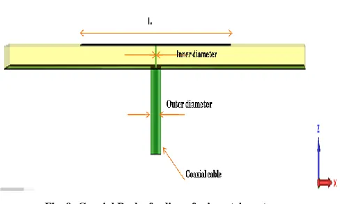
III. COAXIAL FEED
Fig. 9 shows a feeding structure comprising a probe, which extends from a coaxial line and through a ground plane. Such a coaxial probe is commonly used to excite microstrip patch antennas. Usually, a coaxial connector is soldered to the ground plane below a dielectric substrate. By adjusting the location of the feed point, impedance matching between the coaxial line and the radiating patch will be achieved. However, this feeding structure is not suitable for arrays owing to the great number of solder points and coaxial lines [4]. Other limitations include the increase in spurious radiation, surface waves and input inductance for antennas with thick substrates.
Fig. 9: Coaxial Probe feeding of microstrip antenna
[image:3.612.67.267.397.537.2] [image:3.612.324.568.497.643.2]International Journal of Emerging Technology and Advanced Engineering
Website: www.ijetae.com (ISSN 2250-2459,ISO 9001:2008 Certified Journal, Volume 4, Issue 12, December 2014)
[image:4.612.59.269.145.276.2]341 Fig. 10: Return loss characteristics of Coaxial feed
IV. RESULTS AND ANALYSIS
The variation of different antenna parameters with the feeding architecture is analysed. The obtained results are as follows:
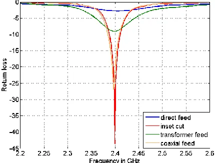
i. Return Loss and Impedance Bandwidth
[image:4.612.60.275.434.597.2]The return loss of the antenna is one of the most important parameter to be studied. The impedance bandwidth associated with the different feeding techniques is defined as -10 dB bandwidth.
Fig.11: Comparison of Return loss of different feeding techniques
ii.Radiation Pattern and Directivity
The radiation pattern of a simple rectangular microstrip patch antenna is in a direction normal to the ground plane and the patch thus forming a broadside pattern [5]. The radiation pattern of the microstrip patch antenna at 2.4 GHz for different feeding techniques are shown in Fig. 12.
a. Direct Microstrip feed
b. Inset cut feed
International Journal of Emerging Technology and Advanced Engineering
Website: www.ijetae.com (ISSN 2250-2459,ISO 9001:2008 Certified Journal, Volume 4, Issue 12, December 2014)
342
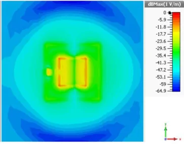
d. Coaxial probe feed
Fig.12: 3D radiation pattern at 2.4 GHz
Directivity is one of the important measure of figure of merit of the antenna. It is basically the capability of the antenna to concentrate the radiated power in one particular direction.
Fig.13: Variation of Directivity for different feeding techniques
iii. Radiation Efficiency
The radiation efficiency is defined as the ratio of the
total power radiated ( ) by an antenna to the net power
accepted (Pin) by the antenna from the connected
transmitter. Neglecting the surface wave losses, since the antenna has its dielectric truncated, the radiation efficiency can be estimated by the following expression:
(2)
Where is the radiated power from the antenna, is
the metallic power loss in the microstrip antenna and is
the dielectric loss in the substrate. So more is the antenna efficiency better is the figure of merit of the antenna as far as undesired losses are concerned.
Fig.14: Variation of antenna efficiency for different feeding techniques
V. CONCLUSION
For thick substrates, which are generally employed to achieve broad BW, both the above methods of direct feeding the microstrip antenna have problems. In the case of a coaxial feed, increased probe length makes the input impedance more inductive, leading to the matching problem. For the microstrip feed, an increase in the substrate thickness increases its width, which in turn increases the undesired feed radiation. The indirect feeding techniques e.g. aperture coupled, proximity coupled solves these problems. This is a scope of future work. Also work can be done in the area of size reduction and increase of directivity by employing Defected Ground structure or use of Metamaterials and Electromagnetic Band Gap structures.
REFERENCES
[1] “Microstrip Antenna Design Handbook”, Ramesh Garg, Prakash Bhartia, Inder Bahl, Apisak Ittipiboon, Artech House, 2001. [2] “Advancement in Microstrip Antennas with Modern Application”,
Ahmed Kishk, InTech, 2013.
[3] David M. Pozar, “Microstrip Antennas”, Proceedings of The IEEE, Vol. 80, No 1, January 1992.
[4] “Microstrip Antennas”, Nasimuddin, Intech, March 2011.