Sewer Design by using Simplified Method, Conventional Method & its
Comparison
Hiradas G. Lilhare
1Dr. Arif Khan
21
PG Student
2Principal
1,2
Department of Environmental Engineering
1,2
Nuva College of Engineering & Technology, Katol Kalmeshwar Road, Nagpur, India
Abstract— Network are an important part of the infrastructure of our society. The investment that is needed for construction and maintenance of this network is so huge and thus any saving in the cost of these networks may result in considerable reduction of total construction cost. The aim of the optimal design of sewerage network is to find a cost effective solution that minimizes capital investment while insuring a good system performance under specific design criteria. Two main cost of sewerage network design are excavation and pipe cost which often create contradictory objective in the design of sewerage networks. Any reduction in pipe size is likely to result in an increase in pipe slope and consequently excavation costs. Reducing excavation cost on the other hand requires milder slopes for pipes, leading to larger pipe size for carrying the design discharge therefore finding an economical design for sewerage networks require an optimal trade-off between pipes and excavation costs which can be easily achieved by engineering judgment. This paper pertains comparison between two methods i.e. simplified method (design 1) and conventional method (design 2).
Key words: Sewerage System, Conventional Method, Simplified Method Manhole Contour, RCC (Reinforced Cement Concrete), PCC (Plain Cement Concrete), Drop Manhole
I. INTRODUCTION
Sewer system is essential for the public health and welfare in all areas of concentrated population and development. Sewer performs the virtually needed function of collecting these wastes and conveying them to point or disposal.
The present project was undertaken to design an efficient sewerage system for Hostel Area (Government College of engineering Chandrapur, 63 acres campus). In this regard, as part of project, assessment of the present condition of the sewerage system and sanitation system was conducted by surveying the nearby areas. Estimation of the daily water requirement available water sources and daily total water usage was conducted. Estimation of the peak runoff was also done. Survey of Hostel area was conducted with help of detailed questionnaire prepared as part of project. Surveying of the area was performed and map of the area showing the land contours was referred. The contour map was used to select and design the gradient and slope of the area for the purpose of laying sewer lines. Hydraulic analysis was also conducted for designing storm drains system. The sewer lines were aligned to ensure economic transport of sewerage to the disposal site. Sewer pipe materials were selected along with fitting and joints for the sewerage system were selected. Sewer appurtenances were also selected for the final design.
In the present study, selected site have the problems due to openly through grey water. It creates the unhygienic
[image:1.595.307.540.275.754.2]environment surrounding the boy’s hostel which causes the growth of flies and mosquitos. It causes disease like malaria, diarrhea, dengue, etc. There is no proper sewerage system is provided for the disposal of grey water. It form the marshy land surrounding the hostel campus. This problem is increasing day by day which we have to remove by providing the proper sewerage system to make campus hygienic. So an effort is needed it design an appropriate sewerage scheme for a hostel, keeping in view the typical requirement and problems related with that includes scattered population, lack of skilled man power and resources.
Fig. 1: Proposed Site (Government Boys Hostel)
Fig. 2: Present Situation of Hostel Campus Due to Openly Spread Grey Water
A. Objectives of Project
The main objectives of the projects are:
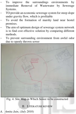
To improve the surroundings environments by immediate Removal of Wastewater by Sewerage Systems.
TO provide an economic sewerage system for steep slope under gravity flow, which is profitable
To avoid the formation of marshy land near hostel premises.
The aim of optimum design of sewerage system network is to find cost effective solution by comparing different methods.
[image:2.595.44.294.93.467.2] To prevent surrounding environment from awful odor due to openly thrown sewer
Fig. 4: Site Map in Which Sewer to be constructed
II. LITERATURE REVIEW
A. Amita Jain, (July 2010)
The present study for rural human settlement, a sewerage system in kanech village near Ludhiana has been designed. Being a village with human population of 3422 and cattle population of 767, for keeping the sewer depth within the limits and for having four smaller STP at the four village’s ponds, simplified sewerage system has been adopted.
B. Anamika Paul & Mimansa Gulati (Number 2014)
Jaffarpur is locality in the Najafgarh zone of southwest New Delhi. In this regard, as part of the project, assessment of the present condition of the sewerage and sanitation system was conducted by surveying the nearby areas. An estimation of the daily water requirement, available water resources and daily total water usage was conducted.
C. BOB Barnard & Craig Wilson (2007)
This paper present a review design for a sediment trap designed to collect suspended particulate matter from storm water for containing analysis. Design criteria for the potential storm water sediment trap include: ability to trap representative amount of particles.
D. Sara De Toffel (2006)
A critical literature review of the most important regulation in the field of urban drainage led to a consolidation that there
are no clearly defined parameters that can qualify the sewer system performance.
E. Paul Bizier (2007)
This manual provides both theoretical and guidelines for the design and construction of gravity sanitary sewers. The manual conclude with a discussion of the commonly used trenchless and conventional method of sanitary sewer
F. Methodology
At first we collect all the data and research paper on sewer design.
Then we gave visit to Chandrapur Municipal Corporation sewer construction site.
The concluding remark based on study was made. In next stage we have survey the all the premises of
hostel and prepared contouring map.
First we adopted conventional method which is based on CPHEEO manual and standard IS code.
Second we adopted simplified method which is based on trial and error method.
Estimate made for both method and comparison of both method have done.
III. DESIGN PARAMETER
A. Hydraulic Concept
Two hydraulic approaches can be used for the design of sewer i.e. minimum self-cleaning velocity and minimum tractive tension.
The first approach is based on the requirement for a minimum self-cleaning velocity in order to avoid the deposition of solids into pipes. These concept considered that the minimum self-cleaning velocity at peak flow calculated for the system will be enough to carry the solid away. In conventional design the minimum self-cleaning velocity of at least, 0.6 m/s (CPHEEO, 1993) sometimes 1 m/s (Mara, 1996) is considered Simplified sewers are design using 0.5 m/s. as a standard value for self-cleaning velocity. Maximum velocity of flow at which pipe can erode were occur at flow velocity in excess of 4 m/s.
The second approach based on minimum tractive tension, also has the objective of ensuring the transportation of solids. This force is enough to keep the solids in suspensions and prevent the solids deposition.
1) Design of sewer by Conventional System
The estimation of peak flow is calculated by equations is based on: Size of population, percentage of water consumption that returns as sewage (Usually considered a loss of 15 percentage due to water usage that is not collected by housing connection) and k1 and k2 coefficient of max. And hourly variation of flow respectively.
Q (total) = QP+QC
Qc =flow from upstream flow contributions (l/s) Qp =sewage produce from hostel
(i)Discharge calculation from boys hostel (Qp) Qp =(C×k1×k2×P×W)/86400
Qp = (0.8×1.8×1.5×135×200)/86400 Qp = 0.675 l lit/sec
C=Sewage return factor (usually adopted 80%) =0.8 K1=coefficient of maximum daily flow variation=1.8 K2=coefficient of maximum daily flow variation=1.5 P=contributing population =200
W=water consumption (l/person per day) =135 l/d (ii) Storm water load calculation (Qc)
As per monthly data
Rainfall data maximum monthly rainfall= 785.7 mm =0.79m
Catchment area of boys hostel= 4800 m2
Rainfall load (maximum or peak month) =Rainfall in mm (peak) ×catchment area
=0.79×4800 m3 =1.462 lit/sec
2) As per Daily Data (Peak Rainfall)
Sr.
no City
Rainfall from
10/08/2014-11/08/2014
Rainfall from
11/08/2014-12/08/2014
[image:3.595.312.540.69.257.2]1 Chandrapur 62.8 mm 68.3 mm
Table 1:
From rainfall data maximum daily rainfall =68.3 mm = 0.068 m
Rainfall load (maximum or peak day) =Rainfall in mm (peak) ×catchment area =3.77 lit/sec
For combine sewer
Total discharge=Total discharge from boy’s hostel +total discharge from rainfall
=0.675+3.77=4.445 lit/sec
As discharge of 4.445 l/s which is very small discharge hence sewer Design for running half full.
B. Diameter by Conventional Method
By using Mannings calculations and hydraulics characteristics of circular sewer section running in half condition we have calculated diameter of sewer of different section and also by using simplified method diameter for different section calculated.
By Mannings calculations
For sewer running half condition q/Q is d=0.5D Discharge through left and right sewer q= 4.445 l/s =0.00225 cumec
From monograph for discharge 2.225 l/s provide slope 1/100 and dia. 13 cm and from mannings formula Q= (1/n)*A*R2/3*S1/2
D=9.4 cm
But as per CPHEEO Manual minimum diameter of sewer should not be less than 15 cm.
V= (1/0.013)*(0.15/4)2/3*(1/100)1/2
=0.86 m/s
As per CPHEEP velocity should in between 0.6 m/s to 3 m/s
Hence safe. There provides 15cm dia. Of sewer
[image:3.595.52.531.71.678.2]C. Calculation of Invert Elevation
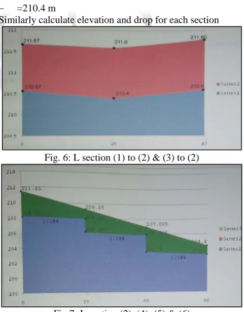
Fig. 5: Proposed Layout For section (1)-(2)
Bench mark of starting point =211.670 m Upper invert elevation = ground elevation –cover =211.670-1.1=210.6 m
Drop in the election of sewer Fall of sewer= 0.01*20.5=0.2m
Lower invert elevation = upper invert elevation – fall of sewer
=210.6-0.2 =210.4 m
Similarly calculate elevation and drop for each section
[image:3.595.286.547.80.678.2]Fig. 6: L section (1) to (2) & (3) to (2)
[image:3.595.308.549.373.681.2]Fig. 8: L section (6), (7), (8), & (9)
Fig. 9: L section (1), (2), & (3)
D. Diameter by Simplified Method
For section (1) to (2)
Length of section = 20.5 m Provides slopes of section = 1:200
Let diameter of sewer to be provided is 150 mm By manning’s equation we have
V = (1/0.013)*(0.15/4)2/3*(1/117)0.5
=0.8 M/S
As per CPHEEO, Design discharge should not be greater than peak discharge.
Qd=A*V
= (pie/4)*0.15*0.15*8=0.0140 cumec.
1) Calculation of Invert Elevation
Upper invert elevation= ground elevation –cover =211.67-1.1=210.67 m
Drop in the elevation of sewer Provided slope = 1/117
Fall of sewer = 0.00854*20.5=0.175 m
Lower invert elevation = Upper invert elevation-fall of sewer
=210.67-0.175=210.4 m
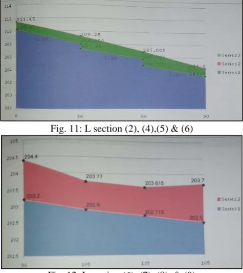
[image:4.595.309.547.69.336.2]Fig. 10: L section (1), (2) & (3)
Fig. 11: L section (2), (4),(5) & (6)
Fig. 12: L section (6), (7), (8), & (9)
IV. MANHOLES/CHAMBER STRUCTURES
Manholes/Chamber should be built at every change of alignment, gradient or diameter, at the head pf all sewers and branches, at every junction of two or more sewers.
Size of sewer Daimeter
Recommended spacing of manholes on straight reaches of sewer line as per IS
1742-1960 Diameter up to
0.3 m 45m
Diameter up to
0.6 m 75m
Diameter up to
0.9 m 90m
Diameter Up to
1.2 m 120m
Diameter Up to
1.5 m 250m
Diameter Greater than
1.5 m
300m
Table 2: Size of Manholes
The minimum internal dimensions of manhole chambers as per IS 1742-1960 are also given in table
Sr.
no Depth Min size specified
1 0.8m or
less 0.75m*0.75m
2 0.8m
to2.1m 1.2m*0.9m
3 Greater than 2.1m
Circular chambers with min dia of 1.4m, or rectangular chamber with
[image:4.595.49.285.69.355.2]V. QUANTITY & COST ESTIMATE OF PROJECT
A. For Conventional Method
Item No
Description
of item Quantity Unit
Rate (Rs) Amount Rs 1 Excavation including filling for manhole in hard soil
131.68 M3 135.44 17834.73
2 PCC(1:4:8)
for manhole 12.45 M3 3404.33 42384.00
3
Excavation including
filling hard soil for
sewer line
194.39 M3 136.24 26483.69
4
Plastering to manhole 15 mm thick
(1:4)
184.824 M3 157.57 29124.37
5
Cement concrete floor of 20 cm (1:2:4)
3.456 M3 5000 17280
6
PCC for laying of sewer in cm
(1:4:8)
20.25 M3 3500 70875
7
Brick in manhole in
cm (1:4)
22.436 M3 5750 129013.27
8 Cement concrete reinforced pipe of 15 cm 20cm
50 M 600 30000
144000 9 RCC for cover of manhole cm (1:2:4)
180 M 800 25918.98
TOTAL
COST Rs 541614.04
Table 4:
B. For Simplified Method
Item No
Description
of item quantity unit
Rate (Rs) Amount Rs 1 Excavation including filling for manhole in hard soil
75.33 M3 135.44 10202.47
2 PCC(1:4:8)
for manhole 6.744 M3 4027.627 27162.322
3
Excavation including
filling hard soil for
sewer line
138.315 M3 136.24 18857.81
4
Plastering to manhole 15 mm thick
(1:4)
145.44 M3 157.3 23035.135
5
Cement concrete floor of 20 cm (1:2:4)
2.304 M3 4957.48 11421.346
6
PCC for laying of sewer in cm
(1:4:8)
13.50 M3 3486.37 47066.00
7
Brick in manhole in
cm (1:4)
17 M3 5822.3 98797.2
8 Cement concrete reinforced pipe of 15 cm 20cm 50 180
M 600
800 30000 144000 9 RCC for cover of manhole cm (1:2:4)
3.5 M 7405.42 25918.98
TOTAL
COST Rs 426461.26
Table 5:
VI. RESULTS & DISCUSSION
As effective sewer design by using these two methods we conclude that the cost estimate by simplified system is more effective and economical than convention system.
The advantage of the simplified sewerage sanitation technology is that a smaller diameter pipe at shallow depth reduces the cost over the conventional sewerage system.
The results show that it is necessary to use the pipe diameter which is available at the market. This means that the minimum diameter of the network should be 150mm.according to the results it is observe that the first check which is the d/D ratio is not satisfied.
The main discussion between the two sewer network design, design 1 and design 2 is to be understood which one of them is economical since the total length of pipe is approximately same, only difference two designs is the volume of excavation. Therefore the total volume of excavation in both design are calculated where the trench width of the excavation is 0.6m for the design 1, the total surface area to be excavated including manhole is measured to be 135 square meters whereas the total volume is estimated to be 326.07 cubic meters. For design 2, the total surface area to be excavated is measured to be 135 square meters whereas the total volume is estimated to be 213.635 cubic meters. According to the results it is observed that the excavation
volume of design 2 is less than design 1 by 35%. The analysis show that
The slope of the sewer is directly proportional with velocity of flow
The roughness of the pipe is inversely proportional with velocity of flow
200mm. it is observe that as the slop increases the change in velocity also increases
Cost of project by conventional method is Rs 541614 Cost of project by simplified method is Rs 426461 Costs are low (25% to 30% less expensive than
conventional sewerage). Because of shallow excavation depth, smaller diameter pipe, simple inspection units.
REFERENCES
[1] Meaning R, (1891). “On the flow of water in open channel and pipes” Inst. Of Civil Eng., 20,161-207 [2] Gupta, A., Mehndiratta, S.L., and Khanna, P. (1983).
“Gravity waste water collection systems optimization”, Journal of Environmental Engineering, ASCE, Vol.109 [3] Otis, R.J and Mara, J., (1985).”The design of small bore
sewer system.”United nation development program, Washington, DC
[4] IS: 4111-(Part1), (1986).” Code of practice for ancillary structure in sewerage design system”Bereau of Indian standard, New Delhi
[5] Sinnatamby, G.S., (1986).”The design of shallow sewer systes” United nation centre for human settlement, Nairobi
[6] CPHEEO, R.W., “Manual on sewerage and sewage treatment”.2 edition Ministry of Urban Development, New Delhi.
[7] Esen,I.I.,(1993), “Design of sewer based on minimum velocity”