6
II
February 2018
Use of MQL Technique to on Different Specimen
during Turning Operation and Calculation of Grey
Relational Co-efficient
Abhishek Dixit1, Dr. Lokesh Bajpai2, Dr. P.L. Verma3, Sandeep Jain4
1
P.G Student, 2Professor, 3, 4 Associate Professor, Department Of Mechanical Engineering, Samrat Ashok Technological Institute, Vidisha1
Abstract: Machining is one of the most important process that is carried out in industries to develop product. The goal of every industry to lower the cost of machining by improving quality and productivity. The machining process mainly depends on the lubricant and heat. If these are in control than tool wear also in control than tool wear also in control. For lower the heat generation, cooling method applied like flood cooling. But flood cooling which is traditional cooling is not successful at every place as well as it hazardous for people working there and for environment also. Flood cooling is very effective at lower cutting speed but not at higher speed because of more heat generation and coolant cannot reach every area of work piece. [1] In tead of flood cooling an alternative comes out that is ‘Minimum Quantity Lubrication’. There are several studies completed and still going on regarding the usage of MQL by manufactures. MQL is the process in which minute amount of high quality lubricant apply to the cutting tool or work piece where flood cooling floods the machining zone in attempt to cool things down but MQL coats the matching zone with a thin film of lubricant and prevents heat buildup as the friction reduces. Majority of the heat from friction transmitted to the chip and exit as chips are removed. There is no disposal problem and it includes mixture of high pressure air and oil. These mixes in the chamber and supply directly to machine zone by nozzle.[2] The usage of MQL technique at machining steel also has a positive effect on performance characteristics such as surface quality and tool wear.[3] It is observed that ,if well pulverized the usage of water added MQL provides a very good lubrication and that is usage of MQL with synthetic ester without water addition harms the cutting tool and has negative effect on the surface roughness of the work piece[4] Besides this, the effect on cooling methods used at manufacturing and the cutting parameters on the performance characteristics constitute the subject of various studies.[5]
Keywords; MQL, turning, cutting fluid, specimen
I. INTRODUCTION
It has been reffered as Minimum Quantity Lubrication. It is alternative of flood cooling. MQL uses lubricant not coolant and in minimum quantity. Coolant which used in flood cooling used to cool thing down but MQL interface with small droplets or a thin layer of lubricant and prevent heat build up. The good lubricity of MQL means heat is transmitted to chip and exit that heat as chip removes. This transfer of heat and lubrication keep the tool and work piece cooler and reduces tool wear. It uses small amount of lubricant which vapourize due to heat and leaves the floor, machine, equipment and tool dry and clean. It is common for machinists to experience the twice the tool life after adopting MQL as well as parts do not require any cleaning before oil are used as lubricant in the MQL which are completely safe for skin contact as well as for environment. MQL includes the high pressure air(6 bar) mix with lubricant in the chamber and supply where machining take place with the help of nozzle and there is no disposal problem as it uses less amount of lubricant which vapourizes due to heat. Product is of high quality and economical as uses less lubricant. The best product includes good surface finish, desired shape and size all thios we can obtained by heat dissipitation from machining zone.[6]
A. Advantages of MQL
1) It uses less amount of lubricant, so almost a dry process which remain safe working environment. 2) Directly applied where machining occurs(between work piece and tool) instead all over.
5) It gives better tool life and surface finish. B. Types of MQL
1) Mixing inside the Nozzle: In this type the lubricant mixes with air inside the nozzle and applied to the machining zone. Mixing chamber present inside the nozzle.
Figure1.1: MQL mixing inside the nozzle
2) Mixing outside the Nozzle: In this mixing chamber is outside the nozzle. Lubricant and air mixes in chamber and supply to the nozzle with the help of oil control valve and than splits on the machining zone.[7]
Figure1.2: MQL mixing outside the nozzle
C. Application of Minimum quantity lubrication
D. Terminology and Methodology
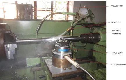
[image:4.612.66.499.140.415.2]The turning experiment done using a heavy duty lathe machine. The experiment was done on a cylindrical job of a stainless steel(17-4PH).The work piece on which the entire experiment was carried out with 42mm in diameter and 400mm in length. The turning experiment was carried out on conventional cooling conditions and minimum quantity lubrication (MQL) system conditions.
[image:4.612.79.525.446.720.2]Figure 2.1: Experimental set-up for conventional cooling
E. Workpiece and Tool material selection
The 17-4PH is used as different aerospace application, chemical processing equipment. This also used as refining for oil, petroleum and equipment for food processing. The chemical composition of the steel are shown in Table 3.1 and in Table 3.2.
Table 3.1: Chemical composition of 17-4PH stainless steel.
Elements C Mn P S Si Cr Ni Cu Nb & Ta
[image:5.612.155.453.221.484.2]Wt% 0.07 1 0.04 0.03 1 17 4 3-5 0.15-0.45
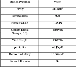
Table 3.2: Physical properties of 17-4 PH stainless steel
Physical Properties Values
Density 7810kg/m3
Poisson’s Ratio 0.29
Elastic Modulus 196GPa
Ultimate Tensile 1103MPa
Strength(UTS)
Yield Strength 1000MPa
Specific Heat 460J/kg-K
Thermal conductivity 18.3W/m-K
Rockwell Hardness 35
The machining was carried out using uncoaed cemented carbide tool inserts.
II. EXPERIMENTATION AND RESULT
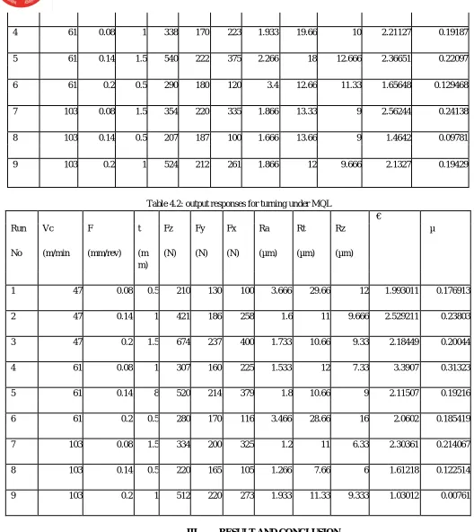
[image:5.612.52.565.565.743.2]After machining, the output responses were measured and tabulated as shown in tables
Table 4.1: output responses for turning under flood cooling environment
Run Vc F t Fz Fy Fx Ra Rt Rz
€
µ
No (m/mi (mm/r (mm (N) (N) (N) (µm) (µm) (µm)
n) ev) )
1 47 0.08 0.5 220 134 105 2.266 14.66 11.33 2.4071 0.22534
2 47 0.14 1 442 190 243 1.866 15 9 2.2777 0.21116
4 61 0.08 1 338 170 223 1.933 19.66 10 2.21127 0.19187
5 61 0.14 1.5 540 222 375 2.266 18 12.666 2.36651 0.22097
6 61 0.2 0.5 290 180 120 3.4 12.66 11.33 1.65648 0.129468
7 103 0.08 1.5 354 220 335 1.866 13.33 9 2.56244 0.24138
8 103 0.14 0.5 207 187 100 1.666 13.66 9 1.4642 0.09781
[image:6.612.40.568.63.655.2]9 103 0.2 1 524 212 261 1.866 12 9.666 2.1327 0.19429
Table 4.2: output responses for turning under MQL
Run Vc F t Fz Fy Fx Ra Rt Rz
€
µ
No (m/min (mm/rev) (m (N) (N) (N) (µm) (µm) (µm)
m)
1 47 0.08 0.5 210 130 100 3.666 29.66 12 1.993011 0.176913
2 47 0.14 1 421 186 258 1.6 11 9.666 2.529211 0.23803
3 47 0.2 1.5 674 237 400 1.733 10.66 9.33 2.18449 0.20044
4 61 0.08 1 307 160 225 1.533 12 7.33 3.3907 0.31323
5 61 0.14 8 520 214 379 1.8 10.66 9 2.11507 0.19216
6 61 0.2 0.5 280 170 116 3.466 28.66 16 2.0602 0.185419
7 103 0.08 1.5 334 200 325 1.2 11 6.33 2.30361 0.214067
8 103 0.14 0.5 220 165 105 1.266 7.66 6 1.61218 0.122514
9 103 0.2 1 512 220 273 1.933 11.33 9.333 1.03012 0.00761
III. RESULT AND CONCLUSION
From the analysis of graphs, it is clear that MQL cutting environment is producing better result by minimizing cutting forces, surface roughness and chip reduction coefficient..
[3] Kalnins et al., 2015; Rudolph et al., 2011; Gilman et al.,2015; Shit et al., 2013; Yun and Shang, 2011; Pirondi and Bonora,2003; Chakherlou and Ajri, 2013 [4] P.C. Paris, F. Erdogan, A critical analysis of crack propagation laws. In: Journal Basic Engineering 85 1963, p. 528-534
[5] R.G. Forman, S.R. Mettu. Behavior of surface and corner cracks subjected to tensile and bending loads in Ti-6Al-4V alloy. In: Fracture Mechanics: 22nd Symposium, Vol. 1 (Eds H.A. Ernst, A. Saxena, D.L. McDowell), ASTM STP 1131, American Society for Testing and Materials, Philadelphia 1992, 519-546 [6] Atrens A, Hoffelner W, Duerig TW, Allison JE. Subsurface crack initiation in high cycle fatigue in Ti6AL4V and typical martensitic stainless steel. Scr Metall
1983;17:601–
[7] Wöhler, A., Über die Festigkeitsversuche mit Eisen und Stahl, Zeitschrift für Bauwesen, Vol. 20, 1870, pp. 73-106. [8] Basquin O. H., Proc. ASTM 10, 625, 1910.
[9] The International Institute of Welding, Stress Determination for Fatigue Analysis of Welded Components, Abington Publishing, Cambridge, England, 1995 [10] punit arora et al ’fatigue crack growth behaviour in pipes and elbows of carbon steel and stainless steel materials
[11] J. Van Wittenberghe , P. De Baets , W. De Waele , T.T. Bui , G. De Roeck ‘Evaluation of fatigue crack propagation in a threaded pipe connection using an optical dynamic 3D displacement analysis technique’
[12] Taheri S. Some advances on understanding of high cycle thermal fatigue crazing. ASME J Press Vessel Technol 2007;129:400–10.
[13] Le Duff A, Tacchini B, Stephan JM, Fissolo A, Vincent L. High cycle thermalfatigue issues in RHRs mixing tees and thermal fatigue test on a representative304L mixing zone. PVP2011-57951, Baltimore, Maryland, USA; 2011
[14] Sonsino CM. Effect of residual stresses on the fatigue behavior of welded jointsdepending on loading conditions and weld geometry. Int J Fatigue2009;31:88– 101.
[15] Ferro P, Berto F, James MN. Asymptotic residual stresses in butt-welded jointsunder fatigue loading. Theoret Appl Fract Mech 2016;83:114–24.
[16] S, Julan E, Tran XV. Fatigue crack growth and arrest under high-cyclethermal loading using XFEM in presence of weld residual stresses. In: Proc of5th conference on crack path (CP-2015) September, Ferrara Italy; 2015.
[17] Sbitti A, Taheri S. Crack arrest in high cycle thermal fatigue. Nucl Eng Des2010;240(1):30–8.
[18] J. Colin, A. Fatemi, Variable amplitude cyclic deformation and fatigue behaviour of stainless steel 304L including step, periodic, and randomloadings, Fat. Fract. Eng. Mat. Struct., 33 (2010), 205 – 220.
[19] A. Palmgren, Die Lebensdauer von Kullagern, Zeitschrift des Vereins Deutscher Ingenieure, 1924, 339–341, (In German). [20] M.A. Miner, Cumulative damage in fatigue, J.Appl. Mech., 12 (1945), 159–164.
![Methyl 6 oxo 4 phenyl 2 [(Z) 2 (pyridin 2 yl)ethenyl] 1,4,5,6 tetrahydropyridine 3 carboxylate](data:image/gif;base64,R0lGODlhAQABAIAAAP///wAAACH5BAEAAAAALAAAAAABAAEAAAICRAEAOw==)