2019 2nd International Conference on Informatics, Control and Automation (ICA 2019) ISBN: 978-1-60595-637-4
Research on Model of Laser Navigation System and Obstacle Avoidance
for Orchard Unmanned Vehicle
Yuan-jie WANG
1,2, Guan-ting PAN
2, Chun-lu XUE
1and Fu-zeng YANG
2,*1Agricultural Information Institute, Chinese Academy of Agricultural Sciences,
Beijing 100081, China
2College of Mechanical and Electronic Engineering, Northwest A&F University,
Yangling 712100, China
*Corresponding author
Keywords: Laser Navigation System, Orchard Unmanned Vehicle, Obstacle Avoidance.
Abstract. To explore the application of laser scanner in the navigation and obstacle avoidance on orchard unmanned vehicle, based on the SICK laser scanner, we established the global coordinate system model, the local coordinate system model and the laser polar coordinate system model and took a person as obstacle detection target and tested the perception results of SICK under different standing postures. The results showed that if the person stand 45° with the scanner, the scanner detection range is 3-6m. The errors between the laser scanner measured width and the actual width of each calibration target were within 5%. In the measuring range of 3 m, the reflectivity had no obvious influence on the measurement accuracy of laser scanner. Compared with the actual value, the average error of waist circumference data obtained by laser scanner at different standing postures was only 5.03%. The results could provide theoretical and data support for the formulation of laser navigation strategy and the development of laser navigation system.
Introduction
With the development of electronic information technology and the improvement of modern agriculture, unmanned vehicle has been gradually extended from the military field to the agricultural field and will be widely used in many agricultural production fields, such as fertilizing, spraying, weeding, transplanting, harvesting and so on[1].
Laser is a new navigation tool developed with the development of laser technology, it is applicable for vehicle navigation, field exploration and other work under poor light. In recent years, many research achievements in the fields of obstacle avoidance, autonomous driving and map construction have been produced. Lindström and Eklundh[2] developed an algorithm that identifies range readings in areas that was detected earlier as free is described without incorporating any grid maps that are inherently memory and computationally consuming. Liu et al.[3] analyzed three typical obstacles belonging to three categories (active obstacles, inactive obstacles and inactive obstacles) based on frequency analysis respectively. Kondaxakis et al.[4] presented an innovative approach that addresses all issues (robot’s relative motion compensation, feature extraction, measurement clustering, data association and targets’ state vector estimation) exploiting various probabilistic and deterministic techniques. Arnay et al.[5] developed a method to combine a low-cost 16 beam solid state laser sensor and a conventional video camera for obstacle detection. Lundell et al.[6] presented a method to estimate the distance directly from raw 2D laser data..
270/spl deg/. Hashimoto et al.[10] used an occupancy-grid-based method to let each robot finds moving people in its scan images, then tracks the detected people via Kalman filter and Global-nearest-neighbor-based data association. Arras et al.[11]proposed an laser-based approach to track people using a multi-hypothesis tracker that detects and tracks legs separately with Kalman filters, constant velocity motion models, and a multi-hypothesis data association strategy. Khan et al.[12] introduced a probabilistic model for interacting targets that addresses both types of measurements simultaneously and provided an algorithm for approximate inference in this model using a Markov Chain Monte Carlo (MCMC) based auxiliary variable particle filter. Qian et al.[13] proposed a method of pretreatment for ROI according to the characteristics of the symmetry of pedestrian's edge, then applied a template matching method based on Hausdorff distance to match the upper-body template by laser scanner's distance refinement.
Although many achievements have been made by research teams, these achievements are mainly concentrated in industrial, transport and other fields, in the agricultural field, especially in the orchard environment, the research of using laser on orchard unmanned vehicle to detect a human obstacle has not been reported. In this research, based on the self-developed orchard unmanned vehicle OUV-2, we established the global coordinate system model, the local coordinate system model and the laser polar coordinate system model, SICK and computer data transmission channel by using TIC/IP communication protocol, the detection distance resolution of obstacle was obtained by calculating the beam diameter and distances between measured points. Combined with the actual working environment of OUV-2, taken a person as an obstacle and conducted the test.
Model Building and Communication Debugging
Main Sensors
The environmental perception sensor adopted is SICK-LMS511-10100 (Sick Sensor Intelligence), there are two distance precision modes, mm and cm. When the mode is set as mm, the maximum measured distance is 8.191 m, and the measuring error is 15 mm; when the mode is set as cm, the measuring distance is 81.91 m and the measuring error is 40 mm. Considering the actual working environment of the OUV-2, the distance precision was set as cm level in this study.
Reflectivity measuring sensor is FieldSpec handheld spectrometer (Analytical Spectral Devices, Inc.) with bundled spectral data acquisition software is RS3™ which can well connect with ENVI® and the data post-processing software ASD ViewSpec™ Pro. The operation of spectrometer is simple and the software has powerful functions. ASD can be used to measure spectral reflectivity, spectral transmittance, radiation and CIE color with the characteristics of high spectral resolution, measuring and observing the spectral curves of reflection, transmission and radiance and displaying absolute reflection ratio in real time, and high signal-to-noise ratio, high reliability, high repeatability, et al.
OUV-2 Laser Navigation System Models
In order to avoid obstacles autonomously for OUV-2, the most important things are to perceive the environment and determine its own posture, the establishment of coordinate system and sensor perception model is the key, reasonable navigation system model can lay a foundation for the research of obstacle perception and obstacle avoidance strategy.
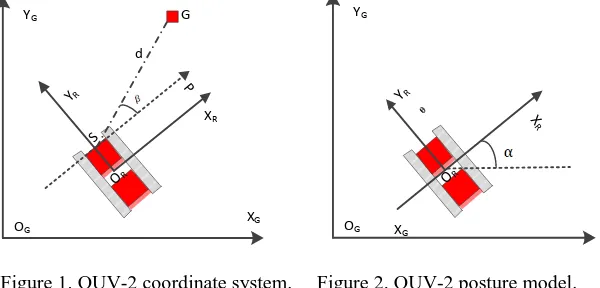
Coordinate System Model. In the coordinate system, there are Cartesian coordinates, polar coordinates (most distance/direction sensors are based on this measurement coordinate system, such as sonar, lidar) and DIN70000 coordinates (based on rectangular coordinates, widely used in the field of robot obstacle avoidance). In the autonomous navigation system of OUV-2, there are three coordinate systems, one is the world coordinate system, also known as the global coordinate system, expressed as 𝑿𝑮𝑶𝑮𝒀𝑮, the second is the local coordinate system of OUV-2, expressed as 𝑿𝑹𝑶𝑹𝒀𝑹
Considering the working environment of the OUV-2 and the sensors adopted, the Cartesian coordinate system was selected for the global coordinate system of OUV-2 working environment and the local coordinate system of the OUV-2; Because every point in the original laser data is represented by the distance d and the scanning angle β, that is (d, β), so the polar coordinate system is chosen as the representation of the sensor coordinate system. The constructed system coordinate system is shown in Figure 1.
The coordinates Xg of the obstacle, the sub-target point of path planning and the issuing of motion
control instructions are all represented by the coordinates in the local coordinate system of the orchard unmanned vehicle; the absolute point in the global coordinate space represents the position of the starting point A and the target point G, the posture of OUV-2 𝑋𝑟 and the position of the sensor 𝑋𝑠 are all represented as the coordinates in the global coordinate system. For simplicity, let the starting point A of the OUV-2 be the origin of the global coordinate system, and the current position B of the OUV-2 be the origin of the local coordinate system which moving with the move of OUV-2. The installation position of the sensor is the origin R of the polar coordinate system, and the direction of R pointing to G is the direction of the polar axis.
The position and pose of OUV-2 determine the position of the OUV-2 in the global coordinate system and the body direction of OUV-2.
[image:3.595.153.453.387.531.2]The position of the OUV-2 is denoted by mass center of the OUV-2 as (x, y), the direction of the vehicle body ɑ is represented by the angle of the front of the vehicle towards the X-axis of the global coordinate system. In this study, the direction angle is defined as 0° on the X-axis, in the clockwise direction as negative and in the counterclockwise direction as positive. The range ɑ is (-180°, 180°), OUV-2 posture model is shown in Figure 2.
Figure 1. OUV-2 coordinate system. Figure 2. OUV-2 posture model.
Laser Scanner Model. Laser used in the research is SICK LMS-511, scan angle is 190°, the effective scan distance is 80 m, the distance and angle resolution are 15 mm and 0.5°, respectively (the number of scan data points are 191). The scan data can be represented by polar coordinates as[14]:
( , ) ,T 1, 2...
n n n
S d n N (1) Or in rectangular coordinates:
( , ) ,T 1, 2...
n n n
S x y n N (2) in which, 𝑥𝑛 = 𝑑𝑛𝑐𝑜𝑠∅𝑛, 𝑦𝑛 = 𝑑𝑛𝑠𝑖𝑛∅𝑛, N is the number of scanning points.
In this research, we chose polar coordinates as laser scanner model, on one hand, SICK provides relative distance and relative direction of the sensor with a certain environment characteristic. Since the laser scanning the surrounding environment to get data according the certain angle resolution in the scanning plane, so the raw data obtained are discrete data points, each point is expressed by a distance d and the corresponding scan angle β, namely the form of (d, β), it is also the reason why we use polar coordinates as a sensor coordinate system. On the other hand, it is also for the convenience of describing and calculating the sub-target point direction angle of the movement of OUV-2. When
XG
OG
YG
OR
S
P
YR
G
d
XR
XG
OG
YG
OR
XR
and cannot visually express vehicle motion direction angle, and using the polar coordinates will greatly facilitate calculation of movement direction angle.
Communication Debugging between SICK and Computer
Communication Protocol. The debugging and parameter settings of SICK were performed through the scanner Terminal port, which based on TCP/IP protocol to connect to computer via Ethernet.
When connecting to a computer over Ethernet, IP addresses of computer and SICK must be on the same network segment, but cannot be the same. According to this principle, we connected SCIK to computer based on TCP/IP successfully. The communication process is no longer repeated.
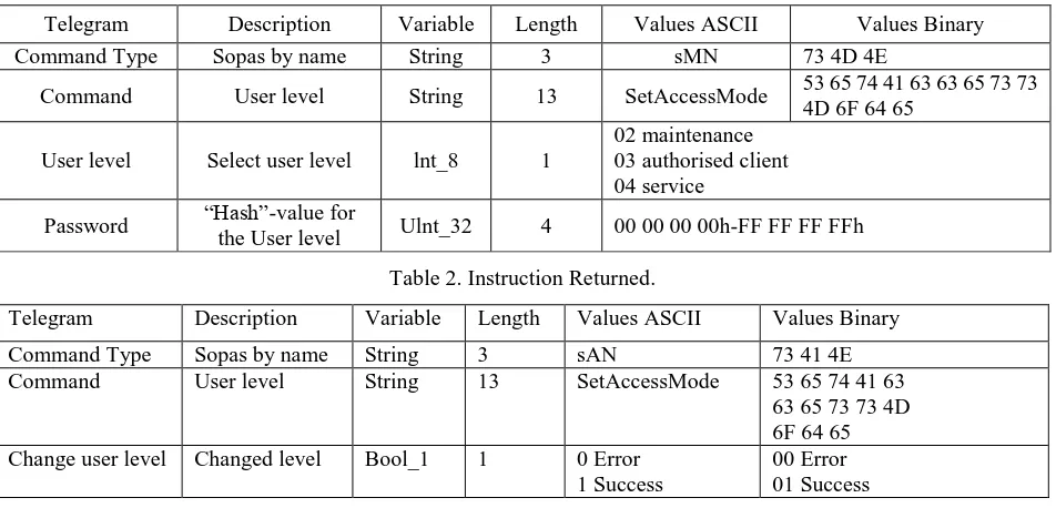
Data Transfer between SICK and Computer. After several times of selective debugging, HERCULES software was adopted for data acquisition, transfer and storage. Set the TCP address and port number to be the same as LMS, send instructions through the instruction box (ASCII code or HEX), then the software returns the value of the response. Table 1 and Table 2 show the scanner login status obtained through the instruction structure.
Computer LMS instruction structure: sMN SetAccessMode. LMS return instruction: sAN SetAccessMode (As shown in Table 1 and Table 2)
Table 1. Instruction structure of Computer LMS.
Telegram Description Variable Length Values ASCII Values Binary
Command Type Sopas by name String 3 sMN 73 4D 4E
Command User level String 13 SetAccessMode 53 65 74 41 63 63 65 73 73 4D 6F 64 65
User level Select user level lnt_8 1
02 maintenance 03 authorised client 04 service
Password “Hash”-value for
[image:4.595.62.538.331.560.2]the User level Ulnt_32 4 00 00 00 00h-FF FF FF FFh
Table 2. Instruction Returned.
Telegram Description Variable Length Values ASCII Values Binary
Command Type Sopas by name String 3 sAN 73 41 4E Command User level String 13 SetAccessMode 53 65 74 41 63
63 65 73 73 4D 6F 64 65 Change user level Changed level Bool_1 1 0 Error
1 Success
00 Error 01 Success
If changed level returns a value of "1", the login is successful. Enter HEX code: 02 73 52 4E 20 4C 4D 44 73 63 63 6E 64 61 74 61 03, then return the current scan data, which is in hexadecimal format.
3 Method and Results Analysis
Obstacle Measurement Accuracy Calculation
A laser emit by Laser LMS511 starts to diverge with the increase of distance.The calculation formula for beam diameter is:
diameter= detection distance 0.011 13
beam mm (3)
The distance between measured points depends on the detection distance and the angular resolution selected.
When laser scans its surroundings, the scan process is a single point measurement at a certain angle. The angle between the two points is the angular resolution of laser. The higher the angular resolution is, the more accurate the measurement result is.
If an object could be detected reliably, the beam must be on the measured object completely, so the obstacle resolution at a certain detection distance = beam diameter + distance between measured points.
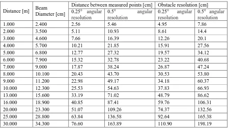
[image:5.595.74.522.202.454.2]After calculation, under the 0.25° and 0.5° angular resolution, results of beam diameter and distance between measured points calculation are as shown in Table 3.
Table 3. Calculation of the basic parameters measured by the laser scanners.
Distance [m] Beam
Diameter [cm]
Distance between measured points [cm] Obstacle resolution [cm] 0.25° angular
resolution
0.5° angular resolution
0.25° angular resolution
0.5° angular resolution
1.000 2.400 2.56 5.46 4.95 7.86
2.000 3.500 5.11 10.93 8.61 14.4
3.000 4.600 7.66 16.39 12.26 20.1
4.000 5.700 10.21 21.85 15.91 27.56
5.000 6.800 12.77 27.32 19.57 34.12
6.000 7.900 15.32 32.78 23.22 40.68
7.000 9.000 17.87 38.24 26.87 47.24
8.000 10.100 20.43 43.70 30.53 53.80
9.000 11.200 22.98 49.17 34.18 60.37
10.000 12.300 25.53 54.63 37.83 66.93 13.000 15.600 33.19 71.02 48.79 86.62 16.000 18.900 40.85 87.41 59.76 106.31 20.000 23.300 51.07 109.26 74.37 132.56 25.000 28.800 63.84 136.58 92.64 165.38 30.000 34.300 76.60 163.89 110.90 198.19
The designed maximum speed of OUV-2 is 4.1 km/h, about 1.14 m/s. According to the calculation results of obstacle resolution in Table 6, under 0.5° angular resolution, with 30 m distance, the maximum obstacle width that the scanner can detect is 1.98 m. In the field, only medium and large agricultural machinery and tools can reach more than 2 m in width, the average waist circumference of adult is 60-100 cm when facing the scanner. Hence, the furthest distance of a person the scanner can detect is 16 m, and the longest reaction time left for the vehicle is 14 s. If the person standing broadside to the scanner, the waist in the scanner plane is only 20-40 cm, that is, the scanner detection range is 3-6 m. In the field, if the laser scanner successfully detects the obstacle with a distance of 30 m, OUV-2 has 26.32 s to receive feedback and makes response, it is enough. Therefore, in combination with OUV-2 itself and its actual operating environment, in the follow-up test, the furthest assessment distance was set as 30 m.
Determination of Gray Reflectance of Calibration Target
Reflectivity of LMS laser is related to the color and roughness of the reflected surface.A rough white surface is defined to have a 100% reflectivity to the LMS laser,for a mirror surface, the reflectivity is greater than 100%. The reflectivity of a bright surface is higher than that of a dark surface.For some dark and rough obstacles, LMS detection distance will be reduced due to laser attenuation.
The calibration targets used in the test were made by technicians from the U.S. Department of Agriculture, Southern Plains Research Center, according to the gray scale. The gray values of the calibration targets used were 28, 119, 221, 255, respectively.
The reflectivity of the calibration target in the wavelength range of 375-1075 nm was determined by using the ASD spectrometer. Since the visible light range is 400-760 nm, we only take the reflectivity in the visible light range as the measured reflectivity value of calibration target. The reflectivity of the white target is 100%.
In the actual test, before a new calibration target is measured, the spectrometer must be calibrated using a white target. The measured average reflectivity of the 4 calibration targets are 45%, 35%, 10% and 4% respectively.
3.3 Influence of Reflectivity on the Measurement Accuracy of Laser Scanner
[image:6.595.61.537.299.492.2]According to the calculated range resolution of the laser scanner, under 0.5° angular resolution, the width of the measured obstacle should be greater than 20 cm. Therefore, according to the width of the calibration target (25.4 cm), we placed calibration targets successively within 3 m range, used the laser scanner to measure and calculate the width of the calibration target, and compared with the actual width of the calibration target, to investigate the influence of reflectivity on the measurement accuracy of laser scanner. The results are shown in Table 4.
Table 4. Reflectivity effect on measurement accuracy.
Reflectivity of calibration target
Distances measured by laser [m]
The measured width of calibration target [cm]
The actual width of the calibration target [cm]
Measurement error [%]
45%
1.066 25.3 25.4
1.71
2.001 24.9 25.4
2.645 24.7 25.4
35%
1.015 25.1 25.4
1.84
2.894 24.9 25.4
3.056 24.8 25.4
10%
0.998 25.2 25.4
2.63
2.134 24.6 25.4
2.635 24.4 25.4
5%
1.126 19.2 19.7
4.23
2.923 18.9 19.7
3.715 18.5 19.7
As can be seen from the results, the measurement error between the width of each calibration target measured by laser scanner and the actual width is within 5%. Therefore, the judgment was within the range of 3 m measurement, the reflectivity has no significant effect on the accuracy of laser scanner.
Detection Test of a Person
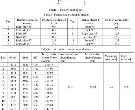
The laser scanner is installed in a position similar to the height of a person's waist on the vehicle, therefore, the perception results of the scanner under different standing posture were tested separately, namely, the influence of obstacle direction on the detection accuracy was investigated (Figure 3). The test scene and the posture and position of the person in the test are shown in Table 5. The data solving model was developed and shown in Figure 4. The test results are shown in Table 6.
[image:6.595.158.441.644.735.2]Figure 4. Data solution model.
Table 5. Posture and position of model.
Test Relative stance to scanner
Position coordinates (x,y) Test
Relative stance to scanner
Position coordinates (x,y) 1 Right side 45° 0,5 7 Front 90° 2,5
2 Left side 45° 0,5 8 Back 90° 2,5
3 Front 90° 0,5 9 Right side 45° -2,5 4 Back 90° 0,5 10 Left side 45° -2,5 5 Right side 45° 2,5 11 Front 90° -2,5 6 Left side 45° 2,5 12 Back 90° -2,5
Table 6. Test results of waist circumference.
Test b[mm] c[mm] A[°]
Test waist circumferenc e a[mm]
Average test waist circumference [mm]
Actual waist circumference
[mm]
Measuring error[mm]
Error ratio[%]
1 4713 4583 4.54 390.44
433.1 456.1 23 5.03 2 4866 4701 4.42 404.09
3 4611 4584 6 481.98 4 4862 4906 5.49 469.86 5 5141 5012 3.2 311.44 6 5118 5104 3.6 321.39 7 5151 4951 4.07 410.65 8 5331 5172 5.02 486.62 9 5120 4881 4.98 495.78 10 5358 5172 4.97 492.93 11 4955 5044 5.52 489.61 12 5215 5361 4.53 442.71
As can be seen from Table 6, when using the laser scanner to obtain the waist circumference data under different standing postures, the measuring error is only 5.03% compared with the actual test results, therefore, it can be considered that the results of measuring waist circumference with laser scanner at different stand postures are reliable and can be used for research on navigation strategy and field experiment.
Conclusions
(1) In this research, navigation system model of Orchard Unmanned Vehicle OUV-2 were firstly established, among them, the global coordinate system of operating environment and the local coordinate system of OUV-2 adopt Cartesian coordinate system model, the sensor coordinate system adopts the polar coordinate system model. SICK and computer communication was established based on TCI/IP protocol, Hercrules software was selected data transmission software between laser and computer.
(2) By calculating the beam diameter and the distances between measured points, the minimum detection resolution of obstacle with different distances was obtained, with the scanner 0.25° and 0.5°
O X
Y
a
b c
respectively. It fully meets the obstacle avoidance needs of the vehicle. The reflectivity of the calibration target has no effect on the measurement accuracy of laser.
(3) A person was chosen as obstacle and was tested with a laser scanner, taking the waist as the testing target, the results show that, compared with the actual measurement results, average error of the waist circumference data obtained by the laser scanner combined with the data solution model under different standing postures is only 5.03%, therefore, the method proposed is reliable and can be used for research on navigation strategy and field experiment.
(4) Relying solely on 2D laser for obstacle avoidance cannot obtain multi-dimensional environmental data, and it is difficult to achieve completely autonomous navigation. Therefore, integrating laser with machine vision or the 3D laser navigation is an important development direction of obstacle avoidance for Orchard Unmanned Vehicle.
Acknowledgement
This research was financially supported by the Basic Scientific Research Operating Foundation Youth Exploration Research Project of Institute of Agricultural Information of CAAS.
References
[1] Zhang L., Ji S., Xu F., et al. Main application domains and key techniques of agricultural robots [J]. Journal of Zhejiang University of Technology, 2002, 30(1): 36-41.
[2] Lindstrom M., Eklundh J. O. Detecting and tracking moving objects from a mobile platform using a laser range scanner[C]//IEEE/RSJ International Conference on Intelligent Robots & Systems. IEEE, 2001.
[3] Liu C., Dong E., Duan Z., et al. Tracking and classification of dynamic obstacles with laser range finder in indoor environments[C]//2015 IEEE International Conference on Robotics and Biomimetics (ROBIO). IEEE, 2015.
[4] Kondaxakis P., Kasderidis S., Trahanias P. E. A multi-target tracking technique for mobile robots using a laser range scanner[C]//IEEE/RSJ International Conference on Intelligent Robots & Systems. IEEE, 2008.
[5] Arnay R., Hernandez-Aceituno J., Toledo J., et al. Laser and optical flow fusion for a non-intrusive obstacle detection system on an intelligent wheelchair[J]. IEEE Sensors Journal, 2018:1-1.
[6] Lundell J., Verdoja F., Kyrki V. Hallucinating robots: Inferring Obstacle Distances from Partial Laser Measurements[J]. 2018.
[7] Xavier J., Pacheco M., Castro D., et al. Fast line, arc/circle and leg detection from laser scan data in a player driver[C]// IEEE International Conference on Robotics & Automation. IEEE, 2006.
[8] Schulz D., Burgard W., Fox D., et al. Tracking multiple moving objects with a mobile robot[J]. Proceedings of the Cvpr, 2001, 1:I-371-I-377.
[9] Zhao H., Shibasaki R. A novel system for tracking pedestrians using multiple single-row laser-range scanners[J]. IEEE Transactions on Systems, Man, and Cybernetics - Part A: Systems and Humans, 2005, 35(2):283-291.
[10] Hashimoto M., Ozaki M., Yokoyama T., et al. Laser-based people tracking by multiple mobile robots[C]// IEEE/ASME International Conference on Advanced Intelligent Mechatronics. 2011.
[12] Khan Z., Balch T., Dellaert F. MCMC Data Association and Sparse Factorization Updating for Real Time Multitarget Tracking with Merged and Multiple Measurements[J]. IEEE Transactions on Pattern Analysis and Machine Intelligence, 2006, 28(12):1960-1972.
[13] Qian H., Yang M., Li H., et al. A pedestrian detection method based on laser scanner and camera[J]. Shanghai Jiaotong Univ. (Sci.), 2010, 44(07):946-0950.