2018 2nd International Conference on Modeling, Simulation and Optimization Technologies and Applications (MSOTA 2018) ISBN: 978-1-60595-594-0
Multiple-Symbol Differential Sphere Detection for Dual-hop
Amplify-and-Forward Relaying Based Differential Spatial Modulation
Feng-yue GAO
1,2,*, Dai-hui MO
2and Lei KONG
31
Army Engineering University of PLA, Nanjing, China
2
Institute of System Engineering Research, Academy of Military Sciences, Beijing, China
3Xi’an Communications Institute, Xi’an, China
*Corresponding author
Keywords: Dual-hop, Differential Spatial Modulation, Multiple-symbol Detection, Amplify-and- Forward.
Abstract. Differential Spatial Modulation (DSM) is a newly MIMO technique, which need no channel state information at the receiver. In this paper, we study the application of DSM in a dual-hop amplify-and forward (AF) relaying system. Owing to the poor performance of conventional differential detection in fast fading channels, we devise a nearly optimal multiple-symbol detector. First, we derive the ML metric, which is not a closed-form expression. Then, a modified suboptimal decision metric is derived instead. Simulation results show that the proposed multiple-symbol detection can effectively improve the performance of DSM in fast-fading channels.
Introduction
Space modulation techniques (SMTs) are illustrated to have advantages over conventional MIMO systems of performance, energy efficiency and hardware cost [1]. Differential spatial modulation (DSM) entirely conserves almost all SMTs inherent strengths without the need of any CSI at the receiver. DSM has been studied in point-to-point communications [2] and relay network [3].
High-Mobility scenarios, e.g., high-speed train (HST) and vehicle-to-vehicle (V2V) scenarios, are expected as typical scenarios for the fifth generation (5G) wireless communication systems [4]. HST wireless communication systems have to overcome many challenges resulting from the high speed of the train, such as fast handover, fast travel through diverse scenarios, and large Doppler spreads [5]. Joint channel and data estimation is able to approach the performance of perfect channel estimation in slow-fading channels [6]. However, both its complexity and pilot-overhead exponentially escalate in high-Doppler scenarios.
Due to the bad performance of “two-symbol” detection in high-mobility scenarios, in this work, a practical suboptimal multiple-symbol differential detection (MSDD), which was first proposed in [7] for point-to-point communications, for DSM system in a dual-hop AF relaying scenario is devised. Owing to the complexity of MSDD increasing exponentially with the size of “observation window”,
Lampe et al. devises the Multiple-Symbol Differential Sphere Detection (MSDSD) in [8] by joint
System Model
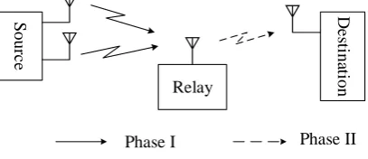
The system is depicted in Fig. 1, where the source equipped with two antenna communicates with a single antenna destination via a single antenna relay. It is assumed that the distance between the source and the destination is beyond the coverage and hence the received signal in the direct link is too
weak to facilitate transmission. Let ht be the fading matrix between the source and the relay. The t-th
received block at the relay can be written as
S
ourc
e
Relay
D
e
st
ina
tion
[image:2.595.183.387.168.256.2]Phase I Phase II
Figure 1. DSM AF relaying system model.
t t t t
r h S n (1)
where rt is the received signal matrix and nt is the AWGN matrix. The entries of ht are assumed to be
i.i.d. complex Gaussian random variables with zero mean and variance 2
h
, and the auto-correlation
value between two channel coefficients, which are n block apart, follows the Jakes fading model:
2 0
( )n hJ (2 f nsr )
(2)
where J0() is zero-order Bessel function of the first kind, fsr is the maximum normalized Doppler
frequency of the channel between the source and the relay. whereas those of nt are assumed to be i.i.d.
complex Gaussian random variables with zero mean and variance N0.
After receiving the signal from the source, the relay amplifies and forwards it to the destination at
the next time instant. Therefore, the t-th received block at the destination can be expressed as
tAgt t t
y r n (3)
where g is the channel gain between the relay and the destination, which follows a Gaussian
distribution of zero mean and variance 2
g
, similarly, the auto-correlation value between two channel
coefficientssatisfies:
2 0
( )n gJ (2 f nrd )
(4)
where frd is the maximum normalized Doppler frequency of the channel between the relay and the
destination. A is the fixed amplification factor of the relay, and nt is the AWGN matrix with zero
mean and variance N0. Substituting (1) into (3) yields
tAgt t t t
y h S n (5)
where ntAgtntnt is the equivalent noise component.
The transmitted signal matrix St satisfies the condition that each transmit antenna is activated only
once. That is to say, St can be a diagonal or anti-diagonal matrix. The transmission signal space of
DSM is given by
1 2
1 2
2 1
, | ,
v v
v v M PSK
v v
(6)
Each information block is constructed by 2b+1 bits. The first b bits are mapped to the symbol v1,
The transmission of the DSM signal will be carried out as follows. First, the initial signal matrix
does not convey any information, without loss of generality, we choose S0=I in this paper. Then, we
compute the actual transmitted signal matrix by differential processing. The t-th transmit block can be
obtained according to
1 t t t
S S V (7)
Assuming quasi-static fading, the t-th received block can be written by the (t-1)th received block as
1 1
t t t t t t
y y V n V n (8)
To get the transmitted information bits, we need to estimate Vt. The optimal ML detector can be
derived as
2 1 1 arg minarg max trace Re( )
t t t F
H t t V V
V y y V
y y V
(9)
Proposed MSDSD Algorithm
This section develops a multiple-symbol differential detection scheme. Let the N received symbols be
collected in vector
1 2
[ , , , N]
y y y y (10) which can be written as
A
y hgS n (11) where
1
1 2 2
1 1 { , , } { , , } [ , , ] [ , , ] N N N N diag
diag g g
S S S
g I I
h h h
n n n
(12)
Therefore, conditioned on both S and g , y is a circularly symmetric complex Gaussian vector
with the following PDF:
1 1
{ | , } exp( )
det{ } H N p
y
y
y S g yΣ y
Σ (13)
y
Σ is the conditional covariance matrix of y ,defined as
2
{ H | , } H H
E A
y h n
Σ y y S g S g Σ gS Σ (14)
h
Σ and Σn are the covariance matrices of h and n ,respectively. i.e.,
2
{ }
toeplitz{1, (1), , (N 1)}
H E h h h
Σ h h C I
C (15)
2 2 2 2 2
0 1
{ }
diag | | +1, , | | +1
H
N
E
N A g A g
n n
n
Σ n n C I
C (16)
1
1 1
ˆ arg max exp( )
det{ } N H N E
g y
V y
V yΣ y
Σ (17)
The ML rule does not get a closed-form expression. Alternatively, it is proposed to use the modified decision rule as follow
1
1 1
ˆ arg max exp( ˆ )
ˆ det{ } N H N
y
V y
V yΣ y
Σ (18)
with
2 2 2
2 0 2
2
ˆ { }
( ) (1 ) ( )
( )
H
g N
H
E
A A N
y y g gh Σ Σ
S C I S I I
S C I S
(19)
where
2 2 2
0
(1 )
toeplitz{1, (1) (1), , (N 1) (N 1)}
g N
A A N
gh gh
C C I
C (20)
The modified decision metric can be further simplified as
1 1 1 1 1 1 2 2 2 2ˆ arg min ˆ
arg min ( )
arg min ( )( )
arg min N N N N H H H
H H H
y V V V V
V yΣ y
yS C I Sy
yS L I L I Sy
U
(21)
L is a lower triangular matrix obtained by the Cholesky decomposition of C-1=LLH
andUySH(LI2). SN=I can be chosen without loss of optimality. Then, combining St+1=StVt, it
follows that
1
2 1
, , 1
1 1
ˆ arg min ( )
N
N N
H
k k k k j k j j k
k j k
l l
VV y V y S S (22)
Simulation Results
In this section, BER simulations in a Rayleigh fading channel are conducted to examine the system performance. All the simulations are conducted with the system setup of a dual-antenna source, a single-antenna relay and a single-antenna destination.
The amplification facor at the relay is fixed to 2
0
/ ( )
r s h
A P P N , where Ps and Pr are power of the
source and the relay. Let Ps = Pr =P/2, where P is the total power.
According to the normalized Doppler frequency of channels, two cases are considered. In Case I,
all nodes are fixed so that channels are slow-fading with the normalized Doppler values of fsr=0.001,
frd=0.001. In Case II, it is assumed that all the channels are mobile, i.e., channels are fast-fading with
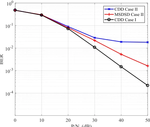
The bit error rate (BER) based on CDD and proposed MSDSD schemes are simulated for two cases. The plot of BER results versus total power is shown in Fig. 2. Considering the poor error
performance of the CDD in Case II, MSDSD with N=4 has a better performance. It can be seen that
[image:5.595.169.415.154.362.2]the MSDSD scheme can overcome the error floor caused by Doppler effect. Compared with slow fading case, the BER performance has a little worse.
Figure 2. BER in different fading cases using CDD (N=2) and MSDSD (N=4) for BPSK.
Summary
In this paper, differential spatial modulation has been applied to dual-hop relay system. With the CDD suffering from an error floor at high SNR in high-mobility scenarios, we propose a suboptimal MSDSD algorithm to overcome the limitation. The simulation results illustrate that, the proposed MSDSD scheme has a better performance over CDD scheme at the expense of complexity.
References
[1] D. A. Basnayaka, M. Di Renzo, and H. Haas, “Massive but few active MIMO,” IEEE Trans. Veh.
Technol., vol. 65, no. 9, pp. 6861-6877, Sep. 2016.
[2] Y. Bian, X. Cheng, M. Wen, L. Yang, H. V. Poor, and B. Jiao, “Differential spatial modulation,”
IEEE Trans. Veh. Technol., vol. 64, no. 7, pp. 3262-3268, Jul. 2015.
[3] M. Zhang, M. Wen, X. Cheng, and L. Yang, “Differential Spatial Modulation for Dual-hop
Amplify-and-Forward Relaying,” in Proc. IEEE ICC, London, U.K., Jun. 2015, pp. 1518-1523.
[4] Wang, C.-X. et al., Cellular Architecture and Key Technologies for 5G Wireless Communication
Networks. IEEE Commun. Mag. vol. 52, pp. 122-130, 2014.
[5] Fokum, D.T., Frost, V.S, A Survey on Methods for Broadband Internet Access on Trains. IEEE
Commun. Surveys Tuts., vol. 12, pp. 171-185, 2010.
[6] Arti, M., Channel Estimation and Detection in Hybrid Satellite-Terrestrial Communication
Systems. IEEE Trans. Veh. Technol., vol. 65, pp. 5764-5771, 2016.
[7] D. Divsalar and M. K. Simon, “Maximum-Likelihood Differential Detection of Uncoded and Trellis Coded Amplitude Phase Modulation over AWGN and Fading Channels-Metrics and
[8] L. Lampe, R. Schober, V. Pauli, and C. Windpassinger, “Multiple-symbol differential sphere
decoding,” IEEE Trans. Commun., vol. 12, pp. 1981-1985, 2005.
[9] P. Ho and D. Fung, “Error performance of multiple symbol differential detection of PSK signals
Transmitted over correlated Rayleigh fading channels,” IEEE Trans. Commun., vol. 40, pp.25-29,
1992.
[10] V. Pauli and L. Lampe, “Tree-Search Multiple-Symbol Differential Decoding for Unitary