2018 International Conference on Applied Mechanics, Mathematics, Modeling and Simulation (AMMMS 2018) ISBN: 978-1-60595-589-6
Seismic Analysis Report for Air Intake Silencer
Jithin Ambarayil Joy, Muhammad Sajjad and Dong Won Jung
*Department of Mechanical Engineering, Jeju National University, Jeju, South Korea
*Corresponding author
Keywords: Silencer, Emergency diesel generator (EDG), Finite element method, Nuclear power plant, Seismic.
Abstract. All internal combustion engines produce noise, the intensity and magnitude of the noise will vary greatly depending upon engine type naturally aspirated or turbocharged, horse power developed, means of scavenging, type of fuel used, number of cycles whether 2 cycle or 4 cycle engine etc. Among the pre-dominant source that makes up the engine noise are the engine intake and exhaust. The silencer plays a very crucial role in these devices for noise controlling which causes vibration in these devices. In this paper we are study about qualification of the intake air silencer for the Emergency Diesel Generator (EDG) of the Shin-Ulchin 1 & 2 (henceforth referred to as SUN12) nuclear power plant. The silencer is of double cylindrical shell construction with absorber material (mineral wool + glass cloth) filling the insulating regions in-between in order to dampen the noise transmission. The finite element method has been relied on in order to evaluate the seismic qualification of the equipment involved. For this purpose, the Finite Element Codes embedded in ANSYS Release 12.1 have been employed.
Introduction
The intake air silencer consists of a plenum type housing which may include chambers and baffles to reduce or dampen the pulsations which have developed in the incoming air flow. Often, some form of sound deadening material may be included. In some installations, the intake air silencer is incorporated into the intake air filter.
Description of the Seismic Qualification Procedure
The finite element method has been relied on in order to evaluate the seismic qualification of the equipment involved. For this purpose, the Finite Element Codes embedded in ANSYS Release 12.1 have been employed. The following load cases are taken into account: Dead Weight (DW), Nozzle loads ELA, ELB, ELD, Operating Basis Earthquake (OBE) and Safe Shutdown Earthquake (SSE). The following load combinations are to be considered for the stress acceptance Normal which is Level A (DW + ELA) Upset Level B (DW + ELB + OBE) and Faulted Level D (DW + ELD + SSE).
In case of nozzle loading (EL), the Allowable Maximum Nozzle Loading is sought of the structure, by applying various nozzle loading cases with various levels of nozzle forces and nozzle moments on both flanges of the silencer. Detailed algorithm for arriving at the Allowable Maximum Nozzle Loading is developed. The algorithm for distributing the nozzle forces and the nozzle moments to the tensile or compressive forces on the flange bolts of inlet and outlet flanges is developed and documented. The modal analysis of the intake silencer has been carried out using the Block Lanczos algorithm within the frequency range of seismic spectra, and natural frequencies have been identified starting from the lower end of this frequency range. Then, the significant modes have been searched for, based on the effective modal mass of each mode in each direction of excitation.
and Level D displacements are computed as the algebraic sum of displacements due to dead weight, nozzle loads and OBE or SSE seismic excitations. For the evaluation of structural integrity of the silencer as per ASME Ⅲ Division 1 Subsection ND 3321, only the stresses produced by static or dynamic loads are included in the combined stresses defined in the previous page. No limits are required of the secondary stresses produced by thermal loads, and hence the thermal stresses are not included in the combined stresses.
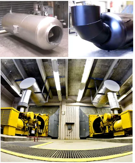
[image:2.595.79.524.161.698.2]Figure 1. The intake air silencer for the Emergency Diesel Generator (EDG) in nuclear power plant.
Here, are the principal stresses. The expression for the stress intensity is shown below;
In thin shell structures, one of the principal stresses is zero. For such structures, the difference between the equivalent stress and the maximum shear stress is rather small. Finally for the evaluation of structural integrity, the Stress Acceptance Criteria of ASME Ⅲ-ND3321
Finite Element Modeling
The finite element analysis is carried out using ANSYS Release 12.0. The finite element model is constructed using shell elements (4 nodes for each element). The following type of element is taken from the ANSYS element library: SHELL63 membrane + bending
The origin of the global coordinate system is located at the geometrical center of the shell. Three axes are set up as follows:
The X axis is in the direction of the flow of the intake silencer
The Y axis is in the transverse direction
The Z axis is in the vertical (upward) direction
Perforated steel plates are employed both for the perforated shell and for the side plates of the splitter, in order to facilitate free air flow into and out of the splitter and the double cylindrical cavity where the sound absorber materials are packed in. Since the perforation of the punch holes are spaced in a hexahedral pattern, the macroscopic density and the elastic properties of perforated plate may be represented as those of orthotropic material. The relationship between the macroscopic material properties of the orthotropic material to the isotropic elastic constants is derived numerically in Appendix C.
The sound absorber material is evenly distributed inside the box-shape space of the splitter, and also inside the double-cylindrical cavity of the perforated shell. It is assumed that the sound absorber material inside the splitter is evenly coated on the side plates of the splitter. Likewise, it is assumed that the sound absorber material inside the double-cylindrical cavity of the perforated shell is also evenly coated on the cylindrical surfaces. This will tend to increase the inertia of the relevant side plates and the cylindrical surfaces. The algorithm for evenly distributing the sound absorber material is derived in Appendix D.
The intake silencer sits on two sets of saddles, one on the inlet side, and the other on the outlet side. The ground plate of the saddle on the outlet side is rigidly fixed by two anchor bolts, whereas the ground plate of the saddle on the inlet side is free to slide in the x-direction, but is fixed in the y- and z- directions. Thus, the nodes at these four anchor bolts act as nodes for the application of fixed boundary conditions, total or partial.
There are two flanges for the intake silencer, inlet and outlet. For the calculation of the natural modes of the silencer, the surfaces of these two flanges are deemed free. Meanwhile, for the application of the nozzle loading, it is the flange bolts that take up the nozzle forces and/or nozzle moments. Thus, for the nozzle loading calculations, the nodes at the flange bolt locations act as the nodes for the application of appropriate traction forces in the x-, y- and z-directions, each calculated as per the formulae derived in Appendix E.
The plots of the finite element model of the intake silencer are shown in detail in the next three pages. The finite element meshing of the intake silencer resulted in the following model statistics:
Summary of Results
The main components of the intake silencer, namely the shell, heads, nozzles, flanges, perforated plates, splitter plates, stiffeners and rib plates all consist of the stainless steel A240 TP304.
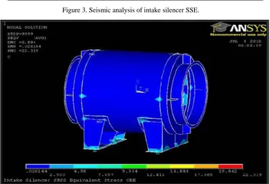
For the spectrum analysis of the intake silencer, the seismic wave spectra plotted in the Appendix A have been applied during the SRSS calculation both for the Operating Basis Earthquake (OBE) and for the Safe Shutdown Earthquake (SSE). The maximum equivalent stresses both for Level B and for Level D loading combinations are calculated.
Hence, it is concluded that the maximum equivalent stresses both for Level B and for Level D loading combinations based on the Allowable Maximum Nozzle Loading are within the Stress Acceptance Criteria described in the Seismic Qualification Procedure of Section 1.2. Finally, the maximum values of the combined stresses due to Level B and Level D loadings are calculated for each component comprising the intake silencer.
Seismic Spectrum Analysis
The dynamic response of the intake silencer subject to the excitation of the seismic waves is calculated through the response spectrum analysis, the theory and the algorithm of which are discussed in Appendix G. Two different types of seismic waves are specified, i.e. Operating Basis Earthquake (OBE) and Safe Shutdown Earthquake (SSE). Since the wave length of the seismic wave is much greater than the size of the silencer, the seismic excitation on the silencer is basically a single point excitation response spectrum (SPRS), meaning that all the excited points will go through the same excitation history.
There are two different types of seismic excitations acting in the z-direction, namely seismic spectra VW and VS. Out of these two, VS represents the vertical seismic wave acting on the slab of the floor, and VW stands for the vertical seismic wave acting on the wall. Since the intake silencer for SKN34 is anchored on wall-mounted platforms, the vertical seismic spectra VW is transmitted to the silencer, but VS is not applied on the intake silencer. The excitation amplitudes of each of these seismic spectra within the frequency range of interest are documented as the seismic spectra in Appendix A. Hence, the acceleration amplitude of the seismic excitation at each of the natural frequencies obtained in the previous Section may be read off the seismic spectra of Appendix A. As is evident from the equations of Appendix G, the SRSS calculation covers the responses of each natural mode to excitations by the seismic spectra. Also, the SRSS calculation takes into account the responses of the intake silencer to the excitations from three independent seismic spectra, namely the NS, EW and the VW spectra. Therefore, the SRSS calculation is carried out in two steps. During the first step, SRSS calculation is done over the natural modes for each seismic spectrum. Then in the second step, the SRSS calculation integrates all the responses from NS, EW and the VW spectra.
Figure 3. Seismic analysis of intake silencer SSE.
Figure 4. Intake silencer SRSS equivalent stress OBE.
Evaluation of Structural Integrity
Combined Stresses
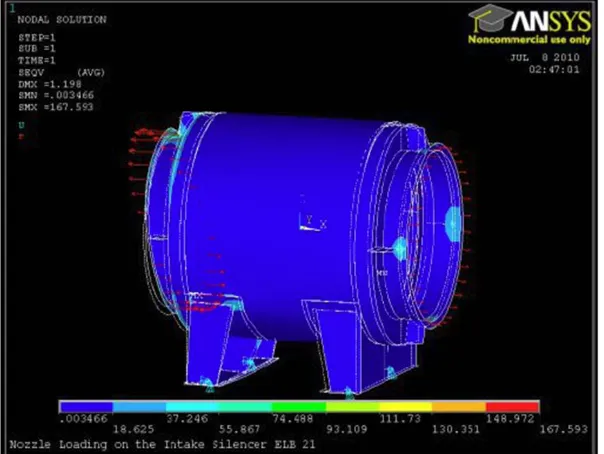
[image:6.595.108.499.407.673.2]dead weight (DW) and the stresses due to nozzle loads (EL) obey the principle of linear superposition.
In general, the Level A, Level B and Level D displacements are computed as the algebraic sum of displacements due to dead weight, nozzle loads and seismic excitations as follows;
Level A = DW + ELA
Level B = DW + ELB + OBE Level D = DW + ELD + SSE
The von Mises equivalent stresses in the SHELL63 elements are then calculated from the nodal displacements. Thus, the equivalent stresses are calculated both for Level B and for Level D loading combinations, and the resulting stress distributions are plotted at the end of this Section.
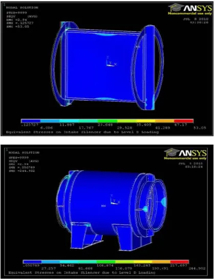
[image:7.595.154.456.322.549.2]The maximum equivalent stresses for Level B and Level D loading both proved to be within the Stress Acceptance Criteria of Section 1.2. Since these maximum equivalent stresses have been obtained from the Allowable Maximum Nozzle Loading posted at Sections 1.4 and 2.1, it may be stated by now that the proposed value for the Allowable Maximum Nozzle Loading is indeed the Allowable Maximum Nozzle Loading, both with the safety margin of only about 15 percent. The stress distributions of von Mises equivalent stresses are illustrated in two plots, below and on the next page. The first plot represents the equivalent stress due to Level B loading combination, and the next one has been obtained from Level D loading combination.
[image:7.595.160.449.576.771.2]Seismic Qualification
[image:8.595.94.514.204.748.2]In Section 3.1, the maximum von Mises equivalent stresses have been calculated and plotted for Level B and Level D service levels. In this Section, the maximum values of the combined stresses due to Level B and Level D loadings are calculated for each component comprising the intake silencer. The component level stress distribution and the maximum von Mises stresses have been calculated for all the components of the intake silencer. As a reference, the component level stress distribution due to the Level D Loading has been plotted for two different assembly levels in the next page, the first with the innermost subassembly of the splitter, the reinforced rings and the reinforced bars, and the second, the saddle structure and the nozzles.
The Component Level Maximum Equivalent Stresses that the combined stresses are concentrated on two areas. The first one is the base plate of the saddle structure, near the welding zone between the base plate and the vertical members. The second place is the nozzle area where rib plates are welded. It is concluded upon examining the combined membrane and the bending stress levels, derived from the Allowable Maximum Nozzle Loading of Sections 1.4 and 2.1, are within acceptable level according to the Stress Acceptance Criteria described of Section 1.2.
Conclusion
In order to compute the response of the intake silencer to the seismic waves, Fifteen natural modes have been accounted for within the frequency range of the seismic spectra. The fundamental modes out of these fifteen natural modes are associated with x-direction, y-direction or z-direction motion of the intake silencer, which is oscillating back and forth with the saddle structure acting mainly as a spring. The stresses arising from the modal responses are most evident in two places, the base plate of the saddle structure, and the nozzle where the rib plates are welded onto. Various levels of Level D loading conditions have been applied on the intake silencer for the calculation of the allowable stresses. Based upon the maximum level of the Level D loading thus found, the stress distribution inside the structural members of the intake silencer has been obtained. The maximum components of the reaction force on the flange bolts have also been calculated from the calculation results of the combined stresses. The analysis of the intake silencer indicates that all the membrane and bending stresses occurring in accordance with the seismic specification of Shin-Ulchin 1 & 2 Nuclear Power Plant will fall within the Stress Acceptance Criteria described in Section 1.2.
References
[1] Astley, R. J. and Cummings, A., 1987, A finite element scheme for attenuation in ducts lined with porous material: comparison with experiment, î Journal of Sound and Vibration 116, 239-263.
[2] ASTM C522-87, 1997, Standard test method for airflow resistance of acoustical materials, American Society for Testing and Materials, 171-175.
[3]ASTM E1050-98, 1998, Standard test method for impedance and absorption of acoustical materials using a tube, two microphones and a digital frequency analysis system, î American Society for Testing and Materials, 951-961.
[4] Beranek, L. L., 1940a, Precision measurement of acoustic impedance, Journal of the Acoustical Society of America 12, 3-13.
[5] Beranek, L. L., 1940b, Acoustic impedance of commercial materials and the performance of rectangular rooms with one treated surface, î Journal of the Acoustical Society of America 12, 14-23.
[6] Beranek, L. L., 1942, Acoustic impedance of porous materials, î Journal of the Acoustical Society of America 13, 248-260.